
1 Introduction
The construction of a large-scale and long distance direct-current transmission line leads to a closer combination of different grids and the wider influence of breakdown.The main mean that for the purpose of accident inversion is using simulation method which rely on reasonable and accurate of simulation model.The Middle Tibet power grid load shedding event due to power oscillation on January 23,2015 and the East China power grid frequency prompt drop due to shutdown of Jinsu direct-current on September 19,2015 have imposed higher requirements on the accuracy of the governor and prime mover of the generator[1,2].
Recently,research institutes and power grid companies have started measurement-based modeling of the generator governor to meet higher requirements for engineering application simulation and accident prevention.Remarkable results were obtained from studies on measurement-based modelling[3-8] and the application of the model[9-14].Increasing number of engineers now pay attention to the influence of low-frequency oscillation of governor parameters[15,16].In general,the parameter setting method for the control system of a governor is useful for theoretical and practical applications as a reasonable and accurate parameter is beneficial to the improvement of system stability and performance of the generator.Optimization of control system parameters combined with measurement-based modeling is important for controllability and observability.
Research on the governor model of a thermal power plant has obvious application in electromechanical transient,as well as medium and long term time domain model[17].Recently,research has shifted to hydropower prime mover model in a dynamic process and some research results have been obtained[6];however,research on parameter setting method,especially in an isolated grid,is relatively rare,and inappropriate parameter setting contributed to the Middle Tibet power grid load shedding event on January 23,2015.
This paper proposes a tuning method for governor control parameters of an isolated hydropower generator considering the primary frequency performance and smallsignal stability.First,generators that can be operated in isolated state were identified based on the operating mode or the examining mode of the power grid.Second,a governor model of the hydropower generator is proposed and a time domain model and frequency domain model of the governor of an isolated generator were constructed respectively to estimate the primary frequency performance and small signal stability.The parameters that satisfy the primary frequency performance and small-signal stability were acquired as the optimal values of governor control parameters.Finally,measurement-based parameters of the governor were identified and verified using simulations to demonstrate the feasibility and effectiveness of the parameter setting algorithm.
2 Model of generator governor
The structure of the generator governor consists of the control system,actuating mechanism,and water tunnel combined with the prime mover model (Fig.1–3).Details of the actuating mechanism model are described in [6-8].The transfer function can be expressed as given in equation(1)using mathematical transformation

In equation (1),PCVis the gate opening setting value,PGVis the gate opening feedback,andτis the inertia time of the actuating mechanism,which is given byτ=T/KP1,whereKP1andTare the proportional gain of the servo card and open/close time (here,the open time is equal to the close time),respectively as shown in Fig.2.In the Fig.,K,KP,KI,KD,andTWare the frequency magnification,the proportional coefficient,the integral coefficient,the differential coefficient of the governor control system,and time constant of water flow for the water diversion pipeline,respectively.
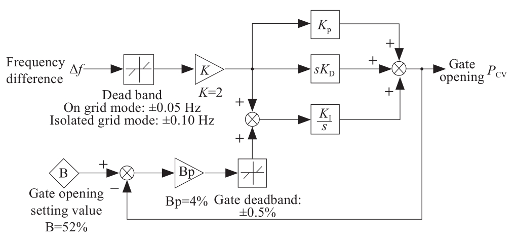
Fig.1 Model of governor control logic
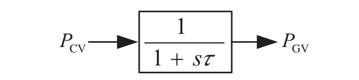
Fig.2 Model of actuating mechanism
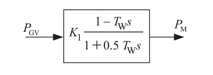
Fig.3 Model of water tunnel and prime mover
3 Characteristic analysis of generator governor
3.1 Dynamic stability factors of generator governor
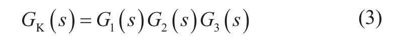
According to Fig.1–3,the open loop transfer function can be obtained as given in equation (2)and the disturbance is the frequency difference.
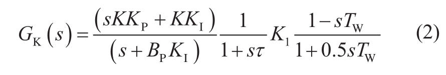
According to small-signal stability analysis theory,the transfer function of the generator is given after the prime mover.Due to the complex transfer function in equation (2),when the generator transfer function is neglected,the open loop transfer functionGK(s)is complex,whereas when the entire transfer function model of the generator is considered,the complexity ofGK(s)increases.On the one hand,values of the generator parameters are mostly design values,and on the other hand,the order of the transfer function model increases when the generator transfer function model is included inGK(s);even in an extreme condition,a stable domain will be difficult to exclude.
Moreover,a simplified generator and load mechanical model can be used for the analysis,as shown in Fig.4 [18].
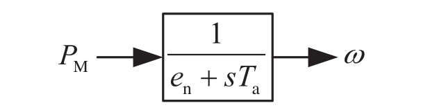
Fig.4 Model of generator and load
To analyze the governor of a hydropower generator in an isolated power grid,the transfer functions from Fig.1–4 are combined and the open loop transfer function diagram is derived as shown in Fig.5.
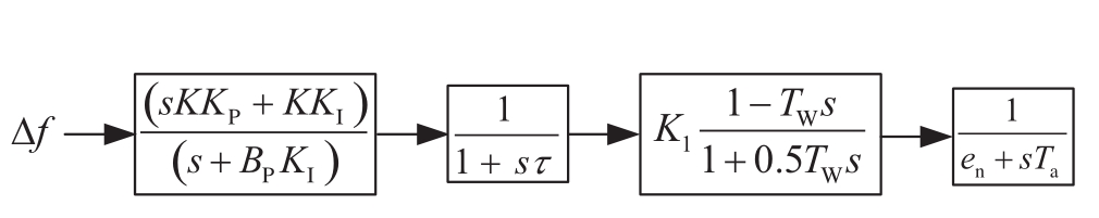
Fig.5 Transfer function diagram of governor control system
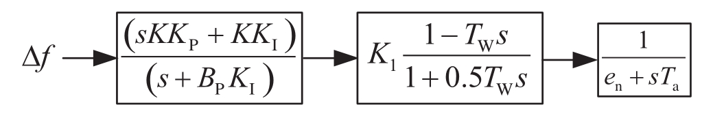
Fig.6 Simplified transfer function diagram of governor control system
As shown above,the model of the actuating mechanism is described in Fig.2,whereτis approximately 0.4–0.8 s.The model shown in Fig.5 can be simplified as shown in Fig.6.
where
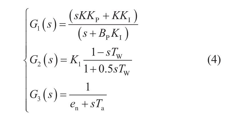
According to automatic control theory,the closed loop transfer function of an open loop transfer function containing unit feedback can be described as in equation (5).
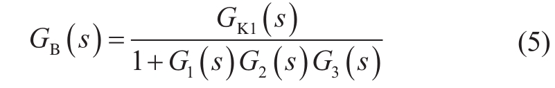
In this equation,GK1(s)is the numerator ofGK(s).According to the closed loop transfer function and automatic control theory [19],to satisfy the stability condition of the control system,the denominator ofGB(s)should satisfya3>0,a2>0,a0>0,anda1a2-a0a3>0.The termsa0,a1,a2,anda3are given as:
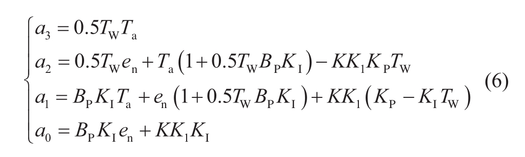
In equation (6),botha3>0 anda0>0 can be satisfied;therefore,analysis should focus on satisfyinga2>0 anda1a2-a0a3>0 for the stability of the system.This shows that whether the stability of the system can be achieved is not only based on control parameters such as PI control parameters but also the parameter value of the water tunnel and prime mover,as well as the parameter value of the generator and load.
The following analysis focuses on measurement-based governor parameters and their values are substituted into equation (6);then,the values of PI parameters can be calculated.
3.2 Key parameters of governor for primary frequency
3.2.1 Performance index conversion of primary frequency
The requirement on the amplitude of the primary frequency response is given in [20];the rising time from 0%to 90% of the settling value must be no more than 12 s in generators that use gate opening as feedback.
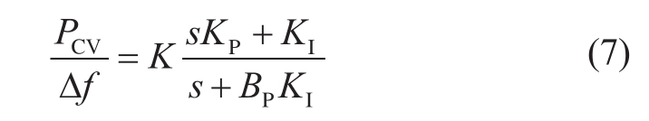
In general,the value ofKDis 0.To analyze the response of the primary frequency in the time domain and judge whether it satisfies the requirement of the guideline[20],the transfer function is disturbed using a frequency step;thus,equation (7)can be transformed to equation (8)
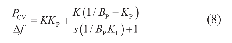
In equation (8),the response of the primary frequency(PF)can be divided into two parts:KKPand [K(1/BP-KP)]/[s(1/BPKI)+1].As the response of PF is given inKKPstep,the time of the response can be neglected and the time trend ofPCVcan be calculated in the second part.
Based on the analysis above,equation (8)can be transformed to equation (9)via inverse Laplace Transform as follows:
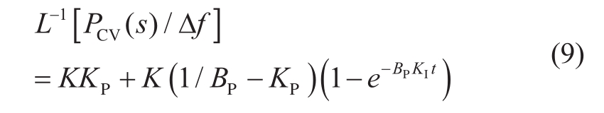
Equation (9)indicates that the response of changing the amplitude of the gate opening instructionPCVfor a step disturbance Δfin the time domain is:
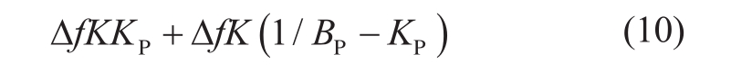
The amplitudeAis equal to ΔfK/BP.To satisfy the guideline [20],the amplitude inT0.9should be up to 0.9ΔfK/BP-ΔfKKP.
According to the time domain function in the above expressions,equation (11)can be derived as follows:

This can be expressed as
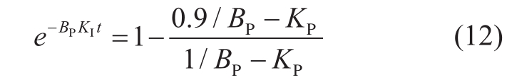
Equation (12)can be transformed to equation (13)and satisfy restraint that less than 12s.
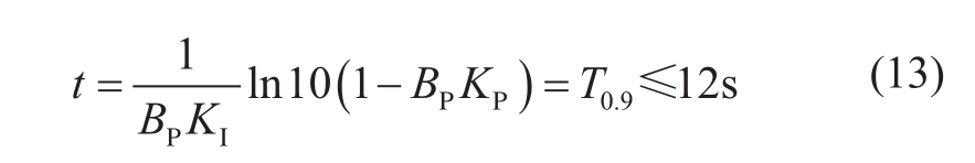
3.2.2 Key control parameters of primary frequency
The dead band (DB)and diversity factor of the governor control system are configured by a power dispatch center in each power grid;the diversity factor and DB of the isolated generator analyzed in this paper are respectively 4% and 0.05 Hz (on grid)or 0.1Hz (isolated).According to equation(13),the control parameter must satisfy:
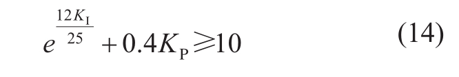
Taking extreme condition into account,when the value ofKIis vey small,KPmust be more than 25.When the value ofKPis very small,KImust be more than 4.8.The key control parameters are the proportional control parameterKPand the integrator control parameterKI.
4 Implementation scheme and parameter setting procedure
4.1 Mechanism analysis
Nowadays,the transfer mechanism of isolated hydropower generator is based on judging the value of the frequency disturbance.In general,the control system can be transferred in some cases;however,the control parameter cannot be accurately transferred in the case of large frequency disturbance,such as deep frequency disturbance in East China Power Grid on September 19,2015.This is because in this type of deep frequency disturbance,the control system of the governor considers it as isolated signal and incorrectly changes the control parameters from primary frequency mode to isolated control mode.Under deep frequency drop condition,the power grid needs a large amount of active power.If the control parameters change incorrectly,the capability of the primary frequency of the hydropower generator would be reduced and the power grid will perform load shedding or even shut down,particularly in a grid with increased amount of hydropower.
In this study,a diagram that provides optimal control of parameters is proposed based on the analysis in sections 3.1 and 3.2,taking the capability of the primary frequency and small-signal stability of the generator governor into consideration.
4.2 Realization scheme
Fig.7 shows a realizing scheme and setting algorithm of the PI control parameters of the governor based on the mechanism analysis above.The scheme consists of six steps.Step 1 gives the topology of the isolated grid via N-2 fault (e.g.,find the grid that contains generators that can be classified into isolated grid through two transmission lines shutdown).Step 2 gives the model parameters of isolated generators′ governor.Step 3 realizes the transfer of model from the frequency domain to the time domain.Steps 4 and 5 provide the PI control parameters setting domain taking the primary frequency capability and small signal stability into consideration.Step 6 is the application of the algorithm and output of the setting parameters.
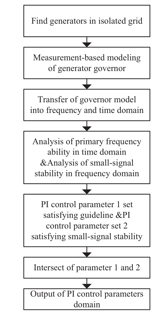
Fig.7 Technical scheme of setting control parameter
5 Example
An isolated grid example was constructed to validate the parameters setting algorithm taking the primary frequency capability and small-signal stability into consideration.First,the parameter values of the governor were identified.The following analysis will focus on the optimization of PI parameters as the parameters of the actuating mechanism,water tunnel and prime mover,and generator and load cannot be adjusted.
5.1 Topology of isolated grid
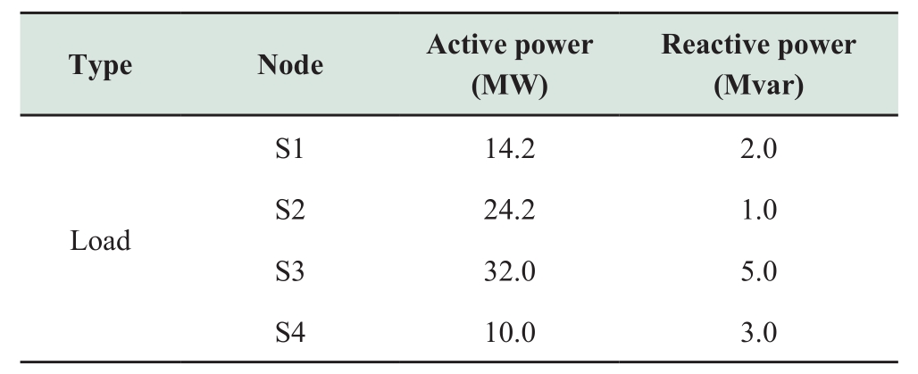
Fig.8 shows the topology of an isolated grid with substations and generators.The isolated grid is connected to the power grid via two 220-kV transmission lines.The nominal active power of each generator is 50 MW,and the output power of the generators is presented in Table 1.The balance generator is the #1 generator,the hydropower type is vertical mixed flow,and the governor type is SAFR-2000H.In this study,the capability of the primary frequency and small-signal stability of generators were simulated under the condition of isolated grid.The isolated grid has four substations (S1,S2,S3,and S4)as presented in Table 2.
Table 1 Active and reactive power of generators in the grid
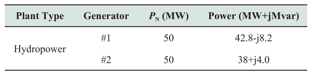
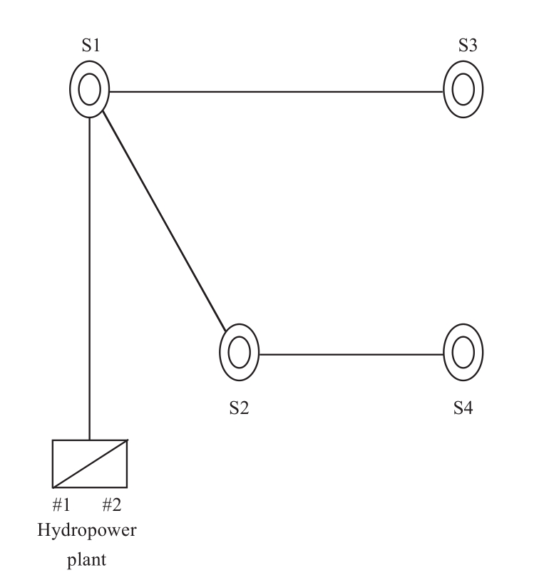
Fig.8 Diagram of hydropower plant with load in isolated grid
Table 2 Loads in isolated grid
5.2 Measurement-based modeling of governor
5.2.1 Modeling of control system
A step disturbance of +0.2 Hz (taking DB of +0.05 Hz into account)was imposed on the control system.The frequency difference and gate opening were recorded,and proportional,integral,and proportional+integral+BPtest were realized.The values ofKP,KI,andBPare identified as 4.5pu,6.4pu,and 4.0%,respectively.This shows that the values set in the control system are equal to real test values.The identification result is shown in Fig.9.The following section will focus on the optimization of PI control parameters taking small-signal stability and capability of the primary frequency into consideration based on the algorithm proposed above.
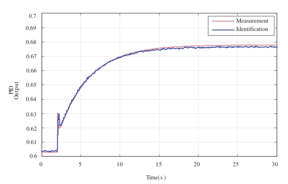
Fig.9 Fitting result ofPCVin control system
5.2.2 Modeling of actuating mechanism
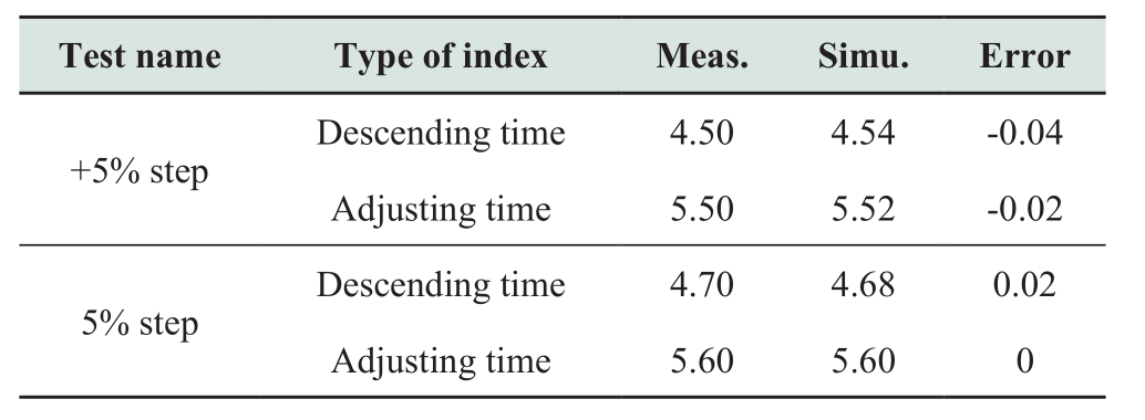
By imposing a step disturbance in the gate opening inner space,the open and close time are obtained asTO=TC= 9.6 s,the PID control parameter is identified asKP1= 20.0 pu,and the inertia timeτis 0.48 s.The results are shown in Fig.10 and Fig.11.
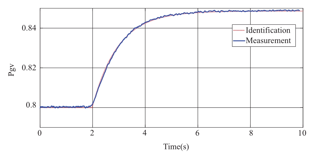
Fig.10 Fitting result of actuating mechanism in +5% step disturbance
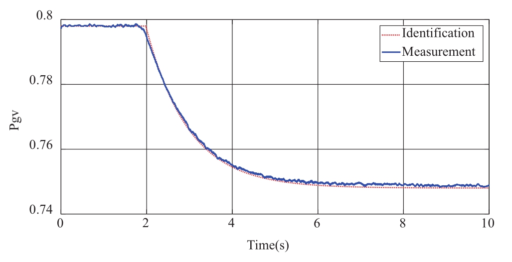
Fig.11 Fitting result of actuating mechanism in-5% step disturbance
Table 3 Fitting result of actuating mechanism in ±5% step disturbance
5.2.3 Modeling of water tunnel and prime mover
A model of the water tunnel and prime mover is shown in Fig.3;the identified parameter values areK1= 2.0,TW=1.36 s.
5.2.4 Modeling of generator and load
A simplified model of the generator and load is obtained using measured data,and the parameter values areen= 3.0pu andTa= 2.6pu.
5.3 Small-signal stability analysis based on model parameters
The termsa0,a1,a2,anda3can be calculated using equation (15)based on the measured data of the prime mover and governor presented in sections 5.2.3 and 5.2.4.
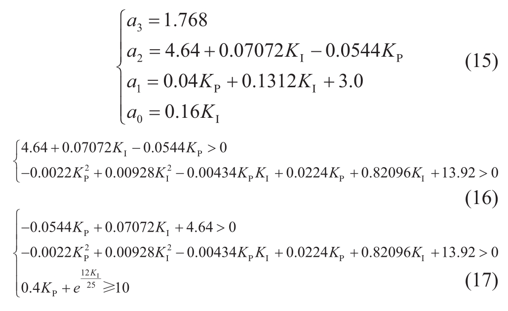
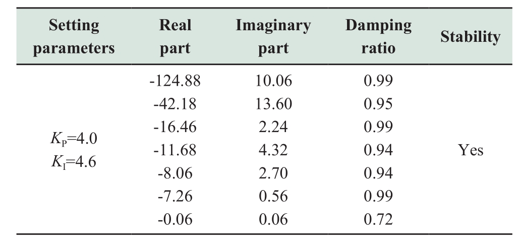
Equation (16)can be obtained using equation (15)combined with the analysis results in section 3.1;smallsignal stability in isolated grid can be assured by the constraint equation in equation (16).The primary frequency capability and stability constraint domain can be obtained by considering equation (14)and equation (16).The PI control parameters are presented in Table 4.The effectiveness of the algorithm proposed in this paper is analyzed by small-signal stability analysis software using the parameters presented in Table 4.The analysis results are presented in Table 5;the results show that using the parameter combinations in Table 4 can provide a high damping ratio and ensure the stability of the isolated grid.
Table 4 Stability analysis of setting parameters obtained from the algorithm
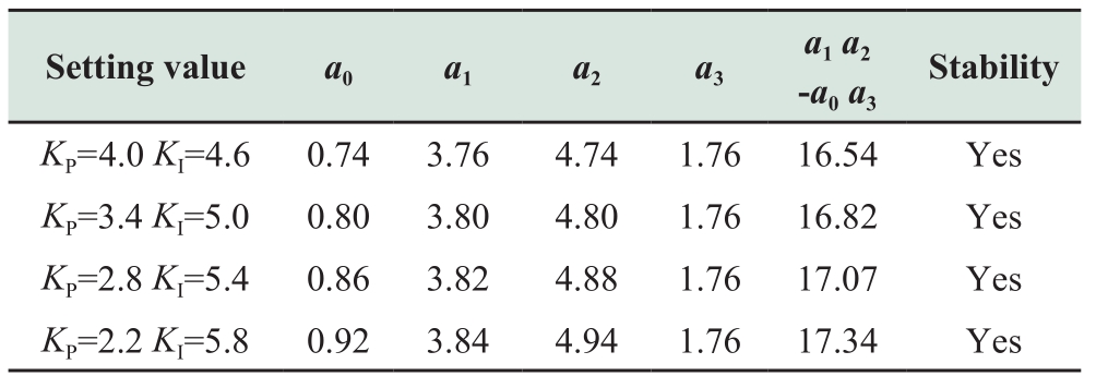
Table 5 Eigenvalues and damping ratio obtained from small signal stability software
5.4 Analysis of primary frequency
Isolated grid simulation model was constructed based on Fig.9.Step disturbances of ±0.20 Hz,±0.15 Hz,and ±0.10 Hz were imposed on the control system.Fig.12–14 showPCVresponses of the control system and the analysis results are presented in Table 6 using the guideline[20] as the standard.
Table 6 Primary frequency capability analysis of setting parameters obtained from the algorithm
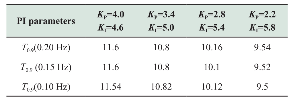
As shown in Fig.12–14,the capability of the primary frequency obviously improved with increasing value of the integral control parameterKI.The result in Table 6 shows that the control parameters combinations satisfy the guideline in reference[20].
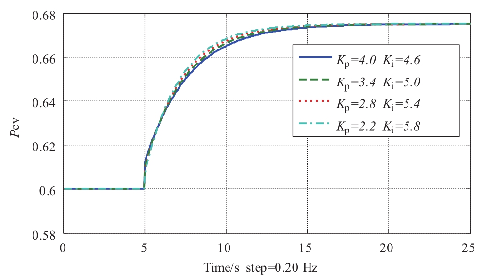
Fig.12PCVresponse to primary frequency step disturbance of 0.20 Hz
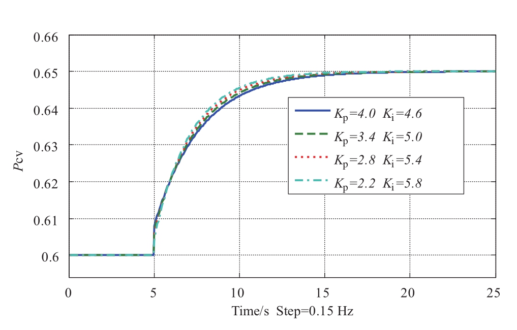
Fig.13PCVresponse to primary frequency step disturbance of 0.15 Hz
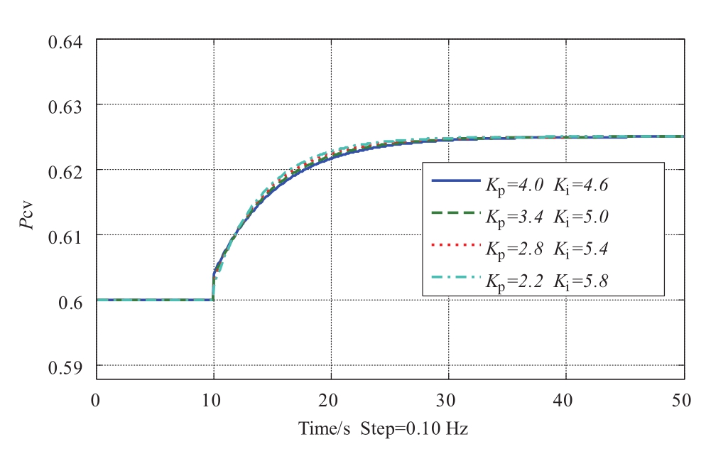
Fig.14PCVresponse to primary frequency step disturbance of 0.10 Hz
6 Conclusion
In this paper,models of the control system,actuating mechanism,hydropower prime mover,and simplified generator and load were presented.The open and close loop transfer functions were obtained.The capability of the primary frequency was estimated using open loop transfer function,and the small-signal stability was analyzed and simulated using mechanism analysis and simulation software.Simulation results were employed to validate theoretical analysis results.The parameter setting algorithm employed measurement-based parameters.The governor control parameters were acquired taking the capability of the primary frequency and small-signal stability into consideration,and simulation results show that the algorithm is effective and robust.
Acknowledgements
This work was supported by the Fujian Provincial Government Project (Title:Research on whole process evaluation of dynamic stability and control strategy in condition of grid connection of ultra-high voltage and large scale penetration of nuclear power.No.2015H0023);the State Grid Science &Technology Project (Title:Research on the improvement on stability of primary frequency of generator in account of the tolerance of equipment.No.52130417002P);the Key project of State Grid Fujian Electric Power Company,Ltd (research on key technologies of primary frequency power oscillation mechanism analysis and inhibition measures in large-scale unit in Fujian power grid.No.52130417000J).
References
[1] Xuan X H,Yin F,Zhang Y J et al (2016)Analysis on Primary Frequency Regulation Performance of the Units under DC Blocking Fault in UHV Receiving End Power Grid.Electric Power,49(11):140-144
[2] Huang J H,Wang H Q,Wang W Y et al (2016)Study on the Security and Stability of Jiangsu Power Grid Based on Multiinfeed DC Assessing Index.Electric Power,49(5):30-36
[3] Zhao Hong G,Liu Z H,Zhu F et al (2007)Research on Mathematical Models and Parameters of Generator Excitation System and Governor System for Stability Analysis of Interconnection of Central China Power Grid with Sichuan-Chongqing Power Grid.Power System Technology,31(5):50-57,63
[4] Working Group on Prime Mover and Energy Supply Models for System Dynamic Performance Studies (1992)Hydraulic turbine and turbine control models for system dynamic studies.IEEE Transactions on Power Systems,7(1):167-179
[5] Zhao J,Liu D C,Wu Y W (2009)Modelling of Pressurized Water Reactor Nuclear Power Plant Integrated into Power System Simulation.Proceedings of the CSEE,29(31):8-13
[6] Deng L,Zhou X J,Zhang W H (2009)Hydro Turbine Prime Mover Model of Governor System for Power System Stability Computation.Automation of Electric Power Systems,33(5):103-107
[7] Kosterev D (2004)Hydro turbine-governor model validation in pacific northwest.IEEE Transactions on Power Systems,19(2):1144-1149
[8] Pereira L,Kosterev D,Davies D et al (2004)New thermal governor model selection and validation in the WECC.IEEE Transactions on Power Systems,19(1):517-523
[9] Sheng K,Liu F P,Liu W L et al (2012)Influence of Steam Turbine Valve Discharge Characteristics on Power Systems and Its Control Strategy.Automation of Electric Power Systems,36(7):104-109
[10] Kishor N,Saini R P,Singh S P (2007)A review on hydropower plant models and control.Renewable and Sustainable Energy Reviews,11(5):776-796
[11] Chen Y T,Li Z H (2005)State Monitoring and Status Analysis of a Hydroturbine Governor Based on the Digitized Model.Automation of Electric Power Systems,29(9):72-76
[12] Deng P,Pi X S,Ma S Y et al (2014)Properties of Power Flow Transfers Under Over-frequency Accident Conditions and Speed Governor State Transition Control.Automation of Electric Power Systems,38(11):123-129
[13] Zhao Q,Liu Z X,Zhang L (2010)Discussions on the Several Problems of Under-frequency Load Shedding Scheme in China.Automation of Electric Power Systems,34(11):48-53
[14] Song F F,Bi T S,Yang Q X (2006)Perturbed Trajectory Prediction Method Based on Wide Area Measurement Systems.Automation of Electric Power Systems,30(23):27-32
[15] Wang C,Li J H,Li Y Y (2013)Low Frequency Oscillation Characteristics of East China Power Grid After Commissioning of Huainan-Shanghai UHV Project.Automation of Electric Power Systems,37(18):120-125
[16] Wen X K,Zhong J L,Qian J (2009)Research on the Control Strategy for Turbine on Low-frequency Oscillation.Proceeding of the CSEE,29(26):107-111
[17] Song X L,Wang C S,Liu T et al (2013)Modeling of Boilerturbine Coordinated Control System in Coal-fired Power Plants for Power System Unified Dynamic Simulation of Transient,Medium-term and Long-term Stabilities.Proceedings of the CSEE,33(25):167-172
[18] Wei S P (2009)Hydraulic turbine regulating.Wuhan:Huazhong University of Science and Technology Press
[19] Hu S S (2017)Theory of Automatic Control.Beijing:Science Press
[20] DL/T 1245-2013 (2013)Technical guideline for grid operation of hydraulic turbine governing system.Electric Power Industry Standard of the People’s Republic of China
2096-5117/© 2019 Global Energy Interconnection Development and Cooperation Organization.Production and hosting by Elsevier B.V.on behalf of KeAi Communications Co.,Ltd.This is an open access article under the CC BY-NC-ND license (http://creativecommons.org/licenses/by-nc-nd/4.0/ ).
86108182 @qq.com
Zhenhua Xu
Received:18 March 2018/ Accepted:20 July 2018/ Published:25 December 2018
Biographies

ZhenhuaXureceived his Ph.D.degree in Electrical Engineering in 2012.He is currently a senior engineer and a member of the CSEE.He is affiliated with the State Grid Fujian Electric Power Research Institute.His main interests are network source coordination analysis,modeling and control of nuclear power generator and wind power generator.