
0 Introduction
The new power system of the future, with new energy generation as its main component, is gradually taking shape [1,2]. However, the high penetration rate of power electronic devices has resul ted in issues such as low inertia and weak damping[3,4], rendering the power system more fragile and posing significant challenges to the safe and stable operation of the power grid [5]. Traditional gridfollowing doubly-fed induction generators are unable to actively provide frequency and voltage support to the system. On the other hand, grid-forming doubly-fed induction generators (GFM-DFIG) utilize virtual synchronous generat or (VSG) control technology to impart synchronous generator-like inertia and damping characteristics to wind turbines [6,7]. This is highly significant in enhancing the safety, reliability, and stabi lity of highpenetration renewable energy grid systems.
The Grid-forming strategy has the capability to establish voltage and frequency autonomously, with minimal reliance on the grid. It can also synchronize with the grid in weak grid, making it highly suitable for application in highpenetration renewable energy power systems[8]. A comparative analysis of the small-signal stability and dynamic characteristics of grid-following and grid-forming DFIG systems suggests that grid-following control exhibits good dynamic characteristics and fast response speed, while grid-forming control reduces transient dynamic characteristics by introducing virtual inertia and virtual damping. However, the virtual synchronization element provides active support to the po wer system,thereby improving the small-signal stability of GFM-DFIG[9].
In response to the issue of small-signal stability in gridfollowing doubly-fed induction generators, literature [10]conducted an analysis of the small-signal stability based on virtual synchronous generator technology. The study investigated the impact of changes in grid strength and control parame ter variations on small-signal stability.However, the research methods and evaluation criteria were not comprehensive enough. Literature [11] utilized the method of characteristic root trajectory analysis to explore the GFM-DFIG based on hybrid power synchronization control. The focus was on the impact of grid impedance and control parameters on small-signal stability during steady-state operation. However, the study did not further investigate small-signal stability issues during transient operation processes.
In the event of a severe grid fault, trans ient issues may arise. Literature [12] proposes a grid-forming strategy for low voltage ride through (LVRT) in GFM-DFIG, which involves switching control modes during the fault. However, it does not investigate the impact of system parameters on LVRT performance. Literature [13] presents a control strategy that uses the power angle characteristic curve and takes into account the effect of current limiting mechanisms [14] on the transient process in virtual synchronous generator (VSG), but it does not clearly define the transient stability boundary.
In summary, there is limited comprehensive research on addressing both small-signal stability and transient stability issues. In order to accurately characterize the smallsignal stability and transient stability characteristics of GFM-DFIG, this study comprehensively investigates the impact of short-circuit ratio and system parameters on the stability of GFM-DFIG. Firstly, a 17th-order fullorder model of GFM-DFIG is established, and a 2ndorder transient model is built based on the full-order model. Then, the transient stability limit voltage (TSLV)under permanent fault conditions is calculated using the transient model as the transient stability boundary, and the quantitative analysis of the influence of different system parameters on the transient stability boundary is conducted.Furthermore,the impact of short-circuit ratio and different parameters on the small-signal stability of GFMDFIG is explored through eigenvalue trajectories and damping ratios, providing recommendations for parameter optimization design.Finally,a GFM-DFIG simulation model is built in Matlab/Simulink, and the simulation results effectively demonstrate the correctness of the theoretical analysis.
1 GFM-DFIG full-order model and 2nd-order transient model
The control block diagram of GFM-D FIG is shown in Fig. 1. The power outer loop on the rotor side adopts a grid-forming control, with the inner loop outputting the stator voltage reference amplitude Uref and synchronous angular velocity θs.
1.1 17th-order small-signal model modeling of GFM-DFIG
The study’s 17th-order small-signal model of GFMDFIG comprises seven components: wind turbine twomass block shaft system model, DFIG model, virtual synchronous control model, rotor-side converter and grid-side converter control models, power grid interface model, and direct current bus model.
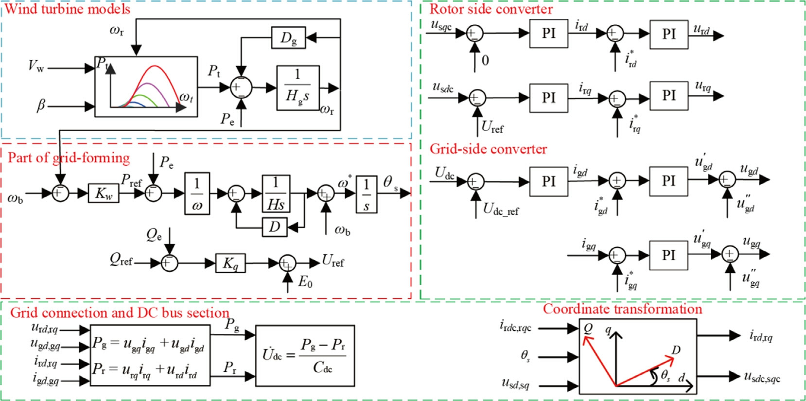
Fig. 1. GFM-DFIG control block diagrams based on virtual synchronization.
1.1.1 Model of wind turbine two-mass flywheel system
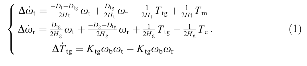
The wind turbine of the DFIG is a dual-speed system that includes the generator speed and the wind turbine speed. Compared to the rotor of the wind turbine and the generator, the rotational inertia of the transmission shafts and gearboxes is small and can be neglected.Therefore, the wind turbine and gearbox can be equivalent to a mass block, and the generator rotor can be equivalent to another mass block.

where, θs is the synchronous angle of VSG; ω is the integral part in the PI controller of VSG; Ps is the stator active power; θs and ω form the stat e variables of the outer link of the virtual synchronous machine power,D is the virtual damping coefficient, H is the virtual inertia coefficient.
1.1.3 Modeling of doubly-fed induction generator
The steady-state magnetic flux linkage of the DFIG’s fixed rotor is conventionally adopted for electric motors.According to the voltage and magnetic flux equations of the DFIG in the synchronous rotating coordinat e system,the 17th-order model of the DFIG with stator current and rotor current as state variables can be derived,as shown in formula (5).

where, ωt is the wind turbine rotor speed, ωr is the generator rotor speed, ωb is the base value of the generator rated speed, θtg is the torsional angle of shaft stiffness, Tm is the wind turbine mechanical torque, Te is the generator electromagnetic torque, Ht is the wind turbine inertia time constant, Hg is the combined inertia time constant of the gearbox and DFIG, Ktg is the shaft stiffness coefficient,Dt is the wind turbine damping coefficient, Dtg is the shaft damping coefficient, Dg is the DFIG damping coefficient.
1.1.2 Modeling of virtual synchronous control
Grid-forming control adopts the virtual synchronous control method to simulate the rotor motion equation and electromagnetic characteristics of the synchronous generator to achieve grid control, enabling the converter to have grid support capabilities similar to those of traditional synchronous motors. The synchronization with the external power grid is achieved through the power synchronization link. The structure is shown in Fig. 2:
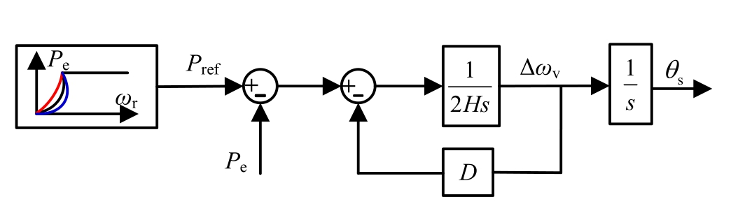
Fig. 2. Diagram of virtual synchronous control.
where, usd、usq is d-axis and q-axis components of the stator voltage in the DFIG; urd、urq is the d-axis and q-axis components of the rotor voltage; Rs is the stator resistance of the DFIG, Rr is the rotor resistance of the DFIG; isd、isq is d-axis and q-axis components of the stator current in the DFIG; ird and irq is d-axis and q-axis components of the rotor current in the DFIG; ωs is synchronous speed,ωsl is the slip speed, defined as the difference between the synchronous speed ωs and the rotor speed ωr.(ωsl=ωs-ωr).
1.1.4 Coordinate transformation
Due to the angular deviation between the control coordinate systems of the grid-side converter and rotor-side converter at the grid connection point and after synchronization, the control variables of the rotor-side and gridside need to be converted to the VSG synchronization angle, as shown in (4).

where, xdc, xqc, XD, XQ are electrical quantities based on the d-q coordinate system of the power grid and transformed to the VSG coordinate system.
1.1.5 DC bus model
The dynamic variation of DC bus voltage can be represented by the power difference between the rotor side and the grid side.
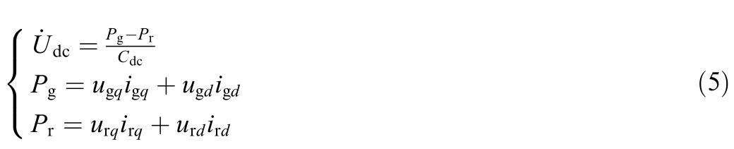
where, Pg and Pr are the powers at the grid side and rotor side; Cdc is the value of the DC capacitor; ugd and ugq are the d-axis and q-axis components of the grid-side voltage;urd and urq are the d-axis and q-axis components of the rotor-side voltage;igd and igq are the d-axis and q-axis components of the grid-side current; ird and irq are the d-axis and q-axis components of the rotor-side current.
1.1.6 Grid interface model
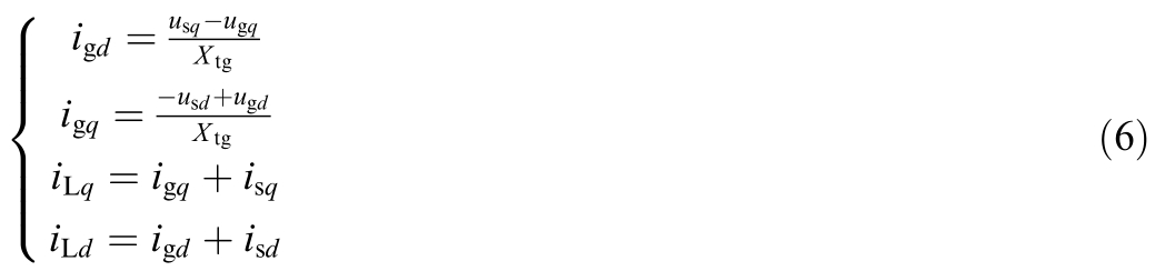
where, Xtg is the impedance on the line, iLd and iLq are the d-axis and q-axis components of the line inductance current.
1.1.7 Control model for rotor-side converter (RSC)
In the GFM-DFIG system, the RSC achieves independent control of active and reactive power through vector control. By adjusting the excitation current, the statorside output voltage is stabilized. To facilitate modeling,four intermediate state variables are introduced [14]:
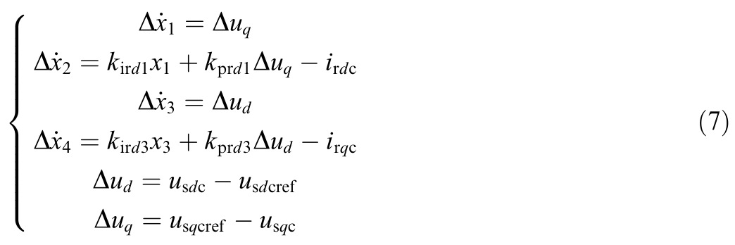
The d-axis and q-axis components urdc and urqc of the rotor excitation voltage provided by the rotor-side converter in the grid-forming coordinate system are respectively:
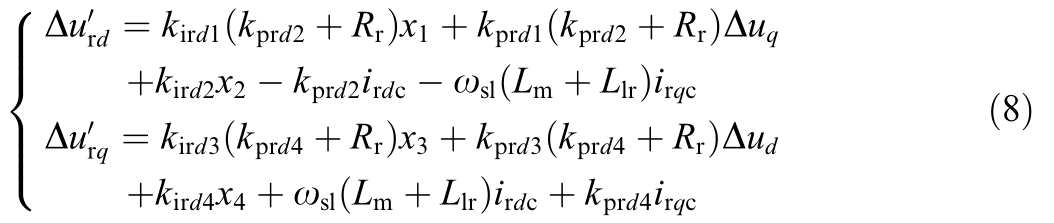
After the addition of the decoupling compensation, the d-axis and q-axis components of the rotor excitation voltage provided by the converter side are as follows:

where, x1, x2, x3, x4 are the integral components of the d and q axis PI controllers for the power outer link an d current inner link of the RSC; usqcref and usdcref are the q-axis and d-axis components of the stator-side synchronized voltage reference; usqc and usdc are the q-axis and d-axis components of the stator-side synchronized voltage; Δud,Δuq are the differences between the actual stator-side voltage and the synchronized reference; irdc and irqc are the daxis and q-axis components of the rotor-side synchronized current; isdc and isqc are the d-axis and q-axis components of the stator-side synchronized current; Llr is the rotor self-inductance.
Where, x1, x2, x3 and x4 are the state variables of the rotor-side converter; Δud, Δuq, irdc and irdc are the input variables of the RSC.
1.1.8 Control model for grid-side converter(GSC)
The main functions of GSC in the GFM-DFIG are to maintain the stability of the DC voltage and control the grid-side reactive power. To facilitate modeling, three intermediate state variables are introduced:
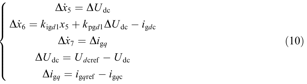
The voltage components of d-axis and q-axis in the output current loop of the power converter shall be as follows:
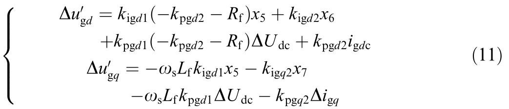
After adding the decoupling compensation, the output voltage components udq of the converter on the grid-side are as follows:

where: x5, x6, and x7 are the integral components in the daxis and q-axis PI controllers of the voltage outer loop and current inner loop of the GSC; udc_ref and udc are the reference value and actual value of the DC bus voltage; igq_ref and igq are the reference value and actual value of the qaxis component of the grid-side current after synchronization; Δudc and Δigq are the differences between the actual values and refer ence values of the DC bus voltage and qaxis component of the grid-side current after synchronization;Lf is the filter inductance;Rf is the filter resistance;x5,x6 and x7 forms the state variables of the GSC; ΔUdc, igdc and Δigq forms the input variables of the GSC.
After linearizing the system model and eliminating intermediate variables, we obtain a 17th-order structured control state-space model for the DFIG system, where the state variables are ωt, ωr, Ttg, ω, θs, isd, isq, ird, irq, x1,x2, x3, x4, x5, x6, x7 and Udc.
1.2 2nd-order transient model of GFM-DFIG
Based on partial data of the GFM-DFIG full-order model, the second-order transient model is built for fast calculation of trans ient stability boundaries.The following measures are taken to construct a low-order transient model [15-17]:
1) By using the high-order model, the rotational speed ωr0 of the wind turbine at the steady-state equilibrium point of the high-order model and the initial value of the rotor current( Irqc0, Irdc0)can be obtained under the conditions of given wind speed v and grid reactance X g.
2)According to the singular perturbation theory, the system is divided into the fast subsystem and the slow subsystem. It is considered that the current inner loop part of RSC belongs to the fast subsystem, while the transient process is a disturbance on the large time scale. Therefore, the current inner loop of RSC can be ignored. Therefore, It is believed that the rotor current can q uickly track the current reference value during the GFM-DFIG transient period. The original integration link is replaced by Irqc0 and Irdc0. The reduced-order RSC control model can be expressed as:

where, kprd1 is the d-axis proportional parameter of the voltage outer loop of the RSC, kird1 is the d-axis integral parameter of the voltage outer loop of the RSC, kprq1 is the q-axis proportional parame ter of the voltage outer loop of the RSC, and kirq1 is the q-axis integral parameter of the voltage outer loop of the RSC.
3) The research focuses on the transient synchronous external characteristics of GFM-DFIG. The phase synchronization link is retained, and the dynamics of the wind turbine,generator and other shafting systems are ignored.
4) I n the process of analyzing the transient stability of GFM-DFIG, the time scale of the dynamic change process of the wind turbine is relatively large. Therefore, the dynamic change process of the wind turbine is ignored. The rotor speed reference value generated by the maximum power point tracking remains unchanged and is replaced by the wind turbine speed ωr0 at the steady-state equilibrium point of the 17thorder model,while the active reference value is given with reference to ωr0:

5) I gnoring the dynamics of the DC bus, considering that the GSC can track quickly and always meet the power balance on both sides of the DC bus,and regarding the GSC as a current source related to the slip rate s:

6) Since Rs and Rr are much smaller than the inductance, the resistance loss is ignored. After order reduction, the terminal voltage Us of the machine is shown as:
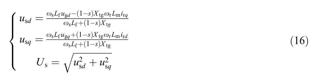
where, Xtg is the reactance of the power grid.
7) In the reduced-order transient model, the rotor motion equation changes from providing the reference phase θv to pro viding the virtual power angle δv

After the above simplifications, the reduced topology of GFM-DFIG connected to the grid is shown in Fig. 3.
2 Transient stability bo undary calculation
This article uses the 2nd-order transient model of TSLV to quickly calculate the minimum permanent fault critical voltage that ensures transient stability through binary search[18,19], and defines the transient stability limit voltage (TSLV), which means that when Ug > TSLV, the GFM-DFIG can maintain transient stability without cutting offthe fault, otherwise it cannot maintain transient stability and needs to cut offthe fault. TSLV is used as the transient operation boundary of the GFM-DFIG, and the high and low of TSLV are used as the basis for analyzing the transient stability of the system, that is, a low TSLV indicates that the GFM-DFIG can operate at a lower transient voltage level with better transient stability.
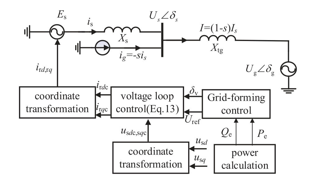
Fig. 3. Reduction topology of GFM-DFIG.
2.1 Impact of system parameters on transient stability of GFMDFIG
According to the singular perturbation theory [20],transient stability issues belong to the electromechanical scale, and the voltage inner loop of the GSC and the RSC belong to the fast subsystem, with dynamics much faster than the grid-forming link and rotor-side current inner loop, resulting in minimal impact on transient stability. Therefore, when analyzing the impact of system parameters on transient stability, only the grid-forming control parameters and RSC current inner loop parameters are considered. When analyzing small-signal stability issues, the focus is mainly on the grid-forming control parameters with significant impact and the grid-side parameters and RSC inner loop parameters that change rapidly.
By using the method of judgment in Section 2, we can obtain the impact of virtual damping D and virtual inertia H on TSLV under different short-circuit ratios as shown in Fig. 3. Surface L represents the low SCR (SCR = 2) condition, while surface H represents the high short-circuit ratio (SCR = 50) condition.
It can be seen from Fig. 4 that increasing D or decreasing H under different SCR can help reduce the TSLV of GFM-DFIG and optimize the transient stability of GFM-DFIG. A higher H will inhibit the decrease in TSLV caused by strong damping. In addition, increasing the SCR can significantly reduce TSLV and enhance the transient operation capability of the system.
As can be seen from Fig. 5, the surface L is under low SCR, and the surface H is under high SCR. kprd1 is the proportional parameter of the d-axis, and kprq1 is the proportional parameter of the q-axis. It can be observed that increasing kprq1 under low SCR can reduce TSLV, while increasing kprq1 under high SCR will increase TSLV. On the other hand, increasing kprd1 under different SCR can reduce TSLV and improve the trans ient stability of the system.
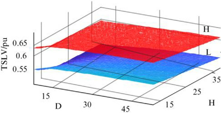
Fig. 4. The influence of D&H on TSLV in different SCR.

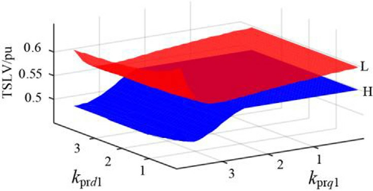
Fig. 5. The influence of kprd1 & kpr q1 on TSLV in different SCR.
It is worth mentioning that due to operating at the transient stability boundary, the rotor current reaches the saturation limit. Under the influence of the q-axis priority strategy, the d-axis current is compressed, and when kprq1 is large, changing kprd1 has no effect on TSLV [21].
In conclusion,from Figs. 4 and 5, it can be seen that D and H, kprd1 and kprq1 impact on TSLV. A smaller TSLV indicates that the system can operate at lower transient voltages. Increasing D or decreasing H, as well as increasing kprd1, can reduce TSLV. Increasing kprq1 reduces TSLV at low SCR, enhancing the transient stability of GFMDFIG;however,at high SCR,Increasing kprq1 will increase TSLV, reducing its transient operational capability.
3 Small-signal stability of GFM-DFIG
3.1 Small-signal stability participation factor analysis
This study examines the operational stability of the proposed grid-forming strategy for GFM-DFIG in weak grid condition. Using the developed 17th-order model, we analyze the small-signal stability by evaluating eigenvalue trajectories across SCR from 50 to 2, as illustrated in Fig. 6.
As shown in Fig. 6, most of the characteristic eigenvalue trajectories move to the left as the SCR decreases,and the system stability is enhanced. Thi s indicates that the GFM-DFIG operates with better stability under the weak grid (SCR = 2).
The following will investigate the influence of control parameters on the stability of the GFM-DFIG system at a low SCR (SCR = 2).
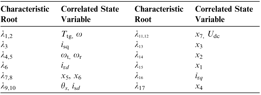
From Fig. 7 and Table 1, it can be concluded that under low SCR, the main participating factors [22] of GFMDFIG λ7,8, λ11,12 are x5, x6, x7, and Udc, which are mainly related to grid-side control parameters. The main participating factors of λ9,10 are θs and isd, which are mainly related to virtual synchronous control and rotor-side control.
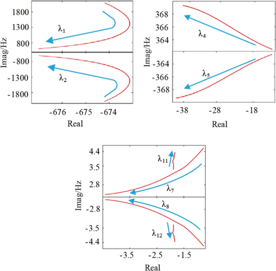
Fig. 6. Plot of full eigenvalue trajectories for GFM-DFIG(SCR 50 to 2).
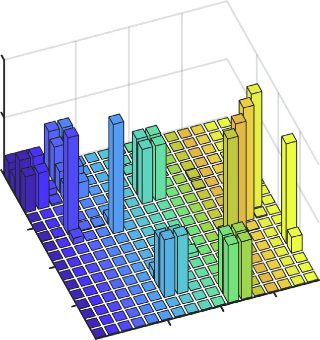
Fig. 7. GFM-DFIG participation factor in low SCR(SCR = 2).
Table 1 GFM-DFIG characteristic root and correlated state variables under low SCR.
Based on the above parameters, the participation factors between system characteristic roots and state variables are plotted under the high SCR (SCR = 50), as shown in Fig. 6.
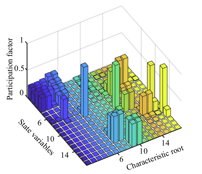
Fig. 8. Participation factor of GFM-DFIG in high SCR (SCR = 50).
Table 2 GFM-DFIG characteristic root and correlated state variables under high SCR.
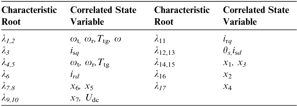
Based on Fig. 8 and Table 2, it can be concluded that the coupling of parameters is more severe at high SCR.This indicates that the control of GFM-DFIG is more complex at high SCR. λ1,2 and λ4,5 are mainly influenced by factors such as ωt, ωr, Ttg, and ω, which are determined by the parameters of the wind turbine itself. λ14,15, λ 16,and λ17 are mainly influenced by factors such as x1,x2,x3,and x4,which are related to the control parameters of the GSC.
In order to further compare the stability of GFMDFIG under different SCR, the changes in eigenvalue trajectories when key parameters of GFM-D FIG are varied are studied at high SCR (SCR = 50) and low SCR(SCR = 2).
3.2 The impact of parameters on the stability of GFM-DFIG
3.2.1 Virtual damping and virtual inertia
From 2.1, it can be seen that λ9,10 in low SCR and λ12,13 in high SCR are greatly influenced by virtual synchronous control. Therefore, by changing the key parameters D and H of virtual synchronous control and observing the changes in the dominant eigenvalues, we can determine the impact of D and H on the stability of the system.
From Fig. 9(a), it can be seen that when the damping D increases under a high SCR, λ12 moves to the left and λ13 moves to the right, but the magnitude of the leftward movement of λ12 is larger, so the eigenva lues λ12 and λ13 tend to be stable overall. From Fig. 9(b), it can be seen that the trend is the same under low SCR as under high SCR. When D increases, λ9 and λ10 move to the left,tending towards stability.
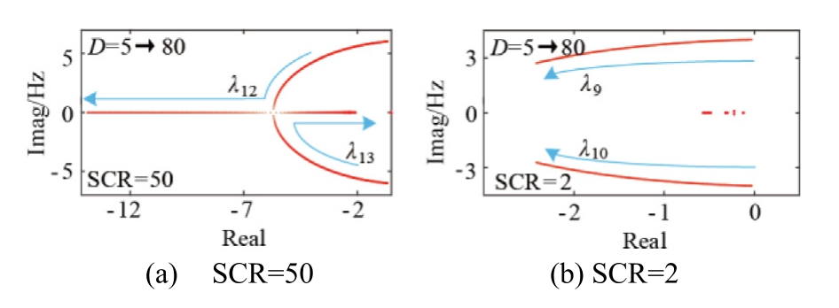
Fig. 9. Virtual damping coefficient D = 5 →80.
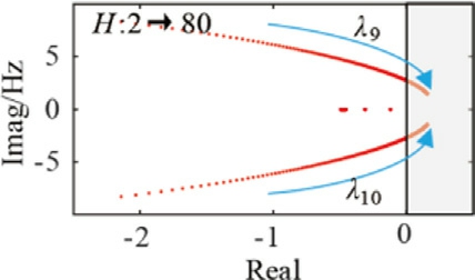
Fig. 10. Virtual inertia coefficient H = 2 →80(SCR = 2).
From Fig. 10, when the virtual inertia coefficient H increases within a certain threshold, the eigenvalue trajectories moves to the right but does not cross the zero point,and the system remains stable with the roots following a certain pattern. When H exceeds a certain threshold, the eigenvalue trajectories of the roots λ9 and λ10, which are greatly affected by the virtual control link, will cross the zero point, indicating system instability.
For a pair of conjugate characteristic roots λ = σ ± jω,the damping ratio ζ and oscillation frequency f they represent are:

The damping ratio affects the attenuation rate of the system oscillation. Therefore, under different system states,by comparing the damping ratio, the stability characteristics of the system can be analyzed. A larger damping ratio usually means that the oscillation of the system will decay more rapidly, thereby enhancing the stability of the system. A smaller damping ratio may cause the system to oscillate for a longer time, manifested as poor stability.Therefore, damping ratio analysis is crucial for evaluating the stability and dynamic response of the system at different operating points.
The above phenomenon indicates that increasing the virtual inertia coefficient H will cause the eigenvalue trajectories to move towards the right half-plane, and may even enter the right half-plane, leading to system instability.The variation trend under high SCR is the same as that under low SCR and will not be elaborated here.
Based on the eigenvalue trajectories, a more precise analysis was conducted on the influence of D and H on the critical modal damping ratio under different SCR,and thus the impact on system stability. As shown in Fig. 10, the red surface represents the influence of D&H on the damping ratio at low short-circuit ratio(SCR = 2), while the blue surface represents the influence of D&H on the damping ratio at high short-circuit ratio(SCR = 50).
From Fig. 11, it can be observed that the trends of the impact of D and H on the small-signal stability of the GFM-DFIG system under different SCR are the same.Increasing D or decreasing H can improve the smallsignal stability of GFM-DFIG, which is consistent with the eigenvalue trajectories analysis results in Figs. 8 and 9. When the inertia is in high level, the small-signal stability of the GFM-DFIG is higher at SCR; when the inertia is in low level,the small-signal stability of the GFM-DFIG is higher at high SCR.
The increase in the SCR raises the lower limit of system stability but lowers the upper limit. By optimizing parameter settings, the H level is increased at low SCR and decreased at high SCR, ensuring good small-signal stability of the system under different SCR.
In summary, although increasing D or decreasing H can improve system stability, it is not advisable to pursue system stability alone. Unrestricted increase in damping and decrease in inertia may lead to a decrease in the response speed of wind turbine, affecting other aspects of performance of GFM-DFIG [21].
3.2.2 Current inner loop parameters of rotor-side converter
The time scale of the small-signal stability problem is relatively small and it is mainly related to the fast subsystem. The voltage outer loop of RSC belongs to the slow subsystem, and the current inner loop of the RSC belongs to the fast subsystem. Therefore, when studying the influence of the control pa rameters of the RSC on the smallsignal stability of GFM-DFIG, only the parameters of the current inner loop need to be studied.Change the integral coefficient kir2 and proportional coefficient kpr2 of the PI in the current inner loop of RSC.
Under different SCR, select the key mode with the greatest impact, and analyze the influ ence of the RSC control parameters on the small-signal stability.
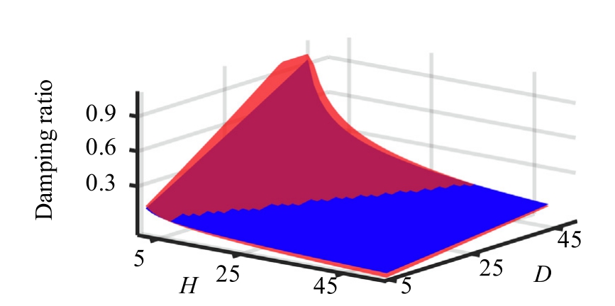
Fig. 11. Influence of D& Hon damping ratio in different SCR.
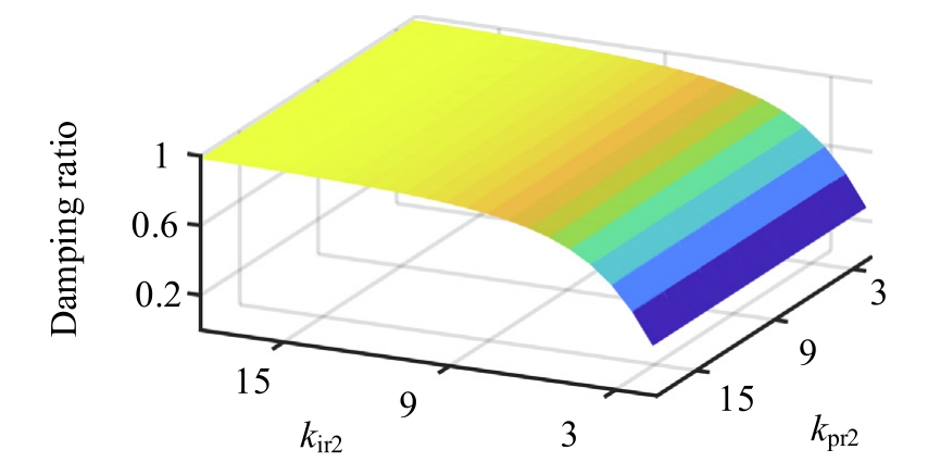
Fig. 12. Current inner loop parameters of RSC under a high SCR(SCR = 50).
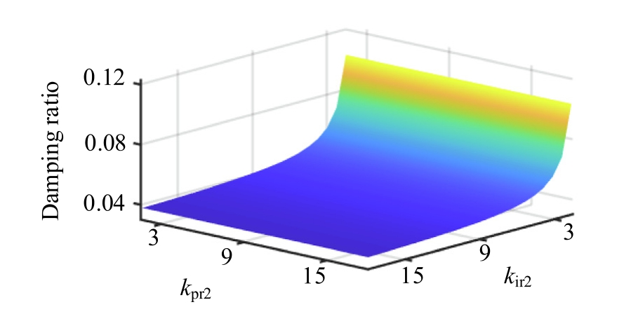
Fig. 13. Current inner loop parameters of RSC under low SCR(SCR = 2).
As shown in Fig. 12, under high SCR, the integral parameter kir2 of the current inner loop on the rotor side has a significant impact on the small-signal stability of the GFMDFIG. With the same proportional parameter kpr2 in the current inner loop on the rotor side, increasing the value of kir2 can significantly improve the small-signal stability;under the same kir2, reducing kpr2 can only slightly improve the system stability,and the effect is not significant.
From Fig. 13, it can be seen that in the low SCR, the proportional parameter kir2 has a significant impact on the control loop of the RSC. The smaller the kir2, the larger the damping ratio,the stronger the small-signal stability of GFM-DFIG, while kpr2 has a much smaller impact on small-signal stability compared to kpr2.
Comparing the influence of the RSC control parameters on the small-signal stability of GFM-DFIG under high and low SCR, it can be concluded that, without switching between grid-following mode and grid-forming control,reasonable tuning of the RSC control parameters can improve the small-signal stability of the GFM-DFIG under different SCR by increasing kir2 under high SCR and decreasing kir2 under low SCR.
3.2.3 Current inner loop parameters of GSC
As shown in Fig. 14, surface H is under the high SCR(SCR = 50), whi le surface L is under low SCR(SCR = 2).In Fig. 14, the variation of parameters in the control loop of GSC has a small impact on the system stability, but is greatly affected by the SCR.The higher SCR,the higher the stability.
The change in parameters has a small impact on the damping ratio of GSC, so the research on the control loop of GSC can be weakened in the analysis of GFM-DFIG small-signal stability issues.
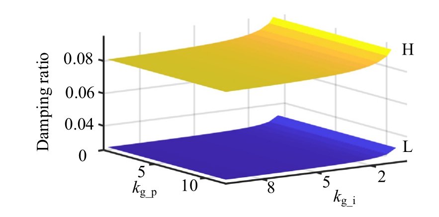
Fig. 14. Current inner loop parameters of GSC on damping ratio under different SCR.
4 Simulation verific ation
To validate the theoretical analysis, this study establishes a MATLAB/Simulink sim ulation model based on the topology shown in Fig. 1 The model is employed to systematically investigate the influence of various parameters on both small-signal stabi lity and transient stability of GFM-DFIG under low SCR conditions.
Initial verification focuses on validating the accuracy of both the small-signal model and transient model.
4.1 Model accuracy validation
As shown in Fig. 15, when the wind speed experiences a step decrease of 1 m/s at t = 30 s, the active power responses of both the small-signal model and the detai led model exhibit excellent agreement. This close correspondence validates the accuracy of the proposed small-signal modeling approach.
From Fig. 16, when the voltage drops by 0.2 p.u. at 30 s, the power change of the reduced-order model is basically consistent with the small-signal model, verifying the accuracy of the transient model.
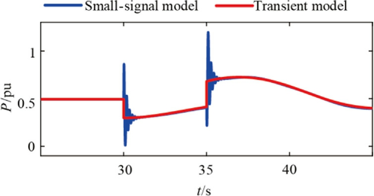
Fig. 15. Comparison between small-signal model and detail model.
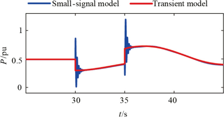
Fig. 16. Comparison between small-signal model and transient model.
This paper employs a reduced-order processing method.Simultaneously, we further validate the accuracy of the second-order model. Through simulation studies, the Critical Clearing Time (CCT) and Critical Clearing Angle(CCA) were obtained for both the second-order and high-order models under varying grid-forming control loop parameters.
The results demonstrate that under low SCR conditions with an 80% grid voltage dip, the GFM-DFIG maintains the longest stable operating duration without losing synchronism. The CCA represents the rotor angle corresponding to the CCT. By comparing the CCT and CCA deviations between the high-order and second-order models, the accuracy of the second-order model is effectively verified. These findings are illustrated in Fig. 17.
The simulation verification reveals distinct relationships between the virtual control parameters and model deviations. As the virtual inertia coefficient H increases, the CCT deviation shows an increasing trend while the CCA deviat ion decreases correspondingly. Conversely, increasing the virtual damping coefficient D leads to reduced CCT deviation but amplified CCA deviation.
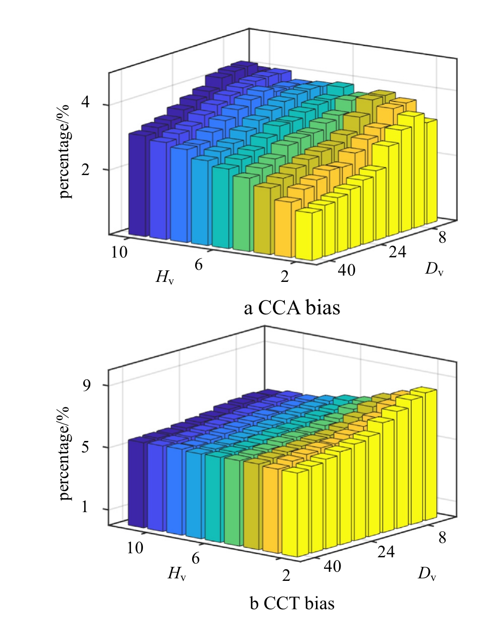
Fig. 17. Transient model bias.
Importantly, all observed deviations between the highorder and second-order models fall within the predefined acceptable range for this study.The high-order model consistently produces more conservative results, generating greater values for both CCT and CCA parameters compared to the second-order model simulations. This inherent conservatism in the high-order model proves particularly valuable for transient stability analysis, as it provides a safety margin that prevents potentially dangerous overestimation of system stability.
These findings collectively demonstrate that the developed second-order model achieves its intended purpose,meeting all necessary requirements for conducting accurate transient stability analysis of GFM-DFIG while maintaining appropriate analytical rigor.
4.2 Verification of the impact of system parameters on TSLV
Setting Ug and 20 s to drop to 0.64 p.u., the simulation waveform is obtained as shown in Fig. 16, with the following parameters set:
a) U g= 0.64, D = 15 / D = 25;
b) U g= 0.64, H = 5/ H = 2;
c) U g = 0.64, kp rd1 = 0.5 / kp rd1= 1;
d) U g= 0.64, kp rq1 = 1/ kp rq1= 2;
In Fig. 18(a), (b), (c), and (d), increasing D, decreasing H, increasing kprd1 and kprq1 at the same drop depth can increase the transient margin of the GFM-DFIG unit,reduce TSLV, and improve the transient stability of the GFM-DFIG. The experimental results validate the correctness of the impact of different parameters on TSLV as discussed in Section 3.
4.3 Verification of the impact of D&H on the small-signal stability of GFM-DFIG
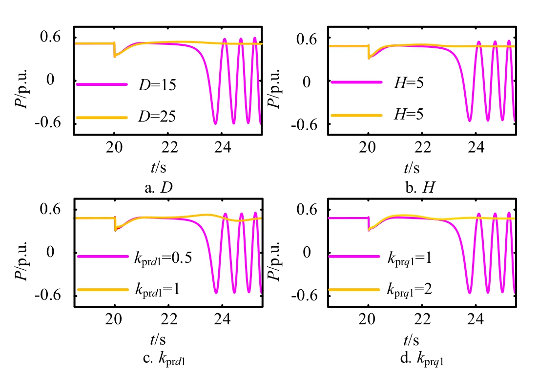
Fig. 18. Simulation verification waveform of TSLV affected by system parameters.
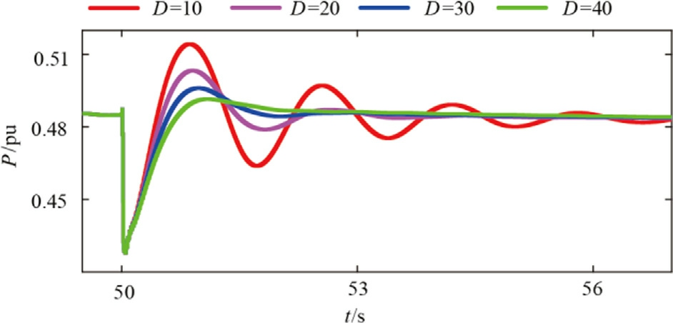
Fig. 19. Active power vWerification waveforms under different virtual damping.
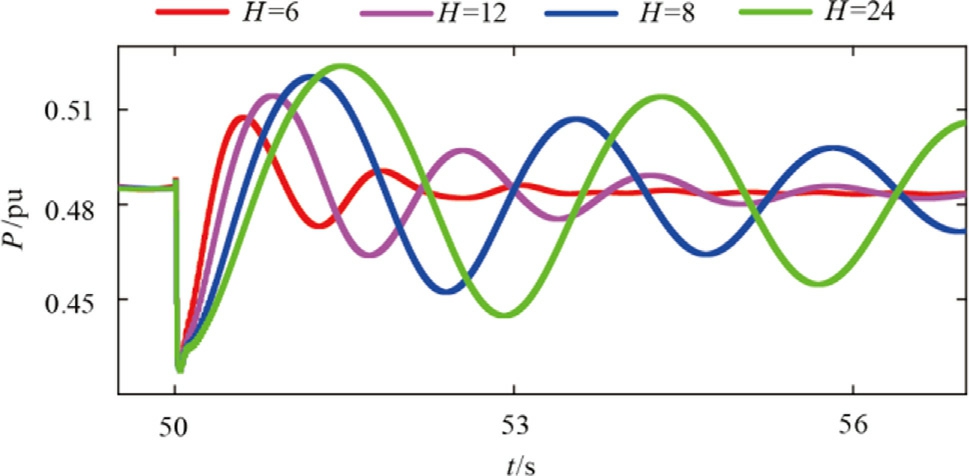
Fig. 20. Active power verification waveform under different virtual inertia.
Under low SCR, the small-signal issues of GFM-DFIG are more prominent, so the verification is only focused on the small-signal issues under low SCR. Combining the conclusions of the fourth section, the changes in the inertia coefficient H and the virtual damping coefficient D have a significant impact on the damping ratio and small-signal stability. Therefore, the following will verify the impact of D & H on the stability of GFM-DFIG.
Set virtual damping D = 10; 20; 30; 4 0 to obtain simulation waveforms in Fig. 19.
Set virtual inertia H = 6; 12; 18; 24, obtain simulation waveform Fig. 19.
From Figs. 19 and 20, increasing D or decreasing H can lead to a faster convergence of the active power output of the GFM-DFIG after the system is disturbed,reducing the risk of system oscillation instability. This result is consistent with the analysis in Section 4 of this paper, which shows that increasing D or decreasing H causes the characteristic root trajectory to move to the left and the damping ratio to increase, validating the correctness of the results.
The results indicate that the adaptability of the unit to the power grid can be improved by appropriately increasing D and decreasing H in practical applications.
5 Conc lusion
This paper investigates the impact of grid impedance and system parameters on the stability of GFM-DFIG units using both transien t and small-signal stability analyses.
First, a full-order model of the GFM-DFIG is developed, followed by a reduced-order transient model. The transient stability limit voltage (TSLV) under permanent fault conditions is calculated, which defines the generator’s transient operating boundary. The influence of grid impedance and system parameters on this transient boundary is then examined. Subsequently, small-signal analysis is performed to derive eigenvalue trajectories and damping ratio variations, revealing the effects of system parameters on stability.
The key findings are as follows:
1) For transient stability, increasing the SCR, enhancing virtual damping D, reducing virtual inertia H,and increasing both kprd1 and kprq1 under low SCR conditions all contribute to lowering the TSLV.This results in a reduction of the transient operating boundary, thereby improving the transient stability of the GFM-DFIG.
2) For small-signal stability, increasing D or reducing H shifts the eigenvalue trajectories leftward, increasing the damping ratio, and thus enhancing small-signal stability. Furthermore, under high SCR conditions,higher inertia levels lead to better stability, whereas under low SCR conditions, lower inertia levels improve stability. Additionally, increasing kir2 in high SCR or decreasing kir2 in low SCR improve small-signal stability, with kir2 having a more pronounced effect than k pr2.
Future research will focus on extending the analysis to wind farms, exploring the transient stability and smallsignal stability of GF M-DFIG in actual wind farm scenarios, which has not been considered in this paper.
CRediT authorship contribution statement
Hui Liu: Conceptualization. Yangfan Zhang: Conceptualization. Ruizhe Zhang: Writing - original draft. Linlin Wu: Methodology. Yaohan Wang: Validation. Kai Liang:Formal analysis. Yu Gong: Formal analysis. Zitong Hao:Writing - review & editing.
Declaration of competing interest
The authors declare the following financial interests/personal relationships which may be considered as potential competing interests: Hui Liu, Yangfan Zhang, Linlin Wu, Yaohan Wang, Kai Liang, Yu Gong are cu rrently employed by State Grid Jibei Electric Power Research Institute. The research project is funded by State Grid Jibei Electric Power Company.
Acknowledgments
The authors gratefully thank the financial support of the State Grid Jibei Electric Power Company, grant number 52018K22001S.
References
[1]K. Hou, Z.Y. Liu, H.J. Jia, et al.,Review of analytical methods for operation reliability assessment of power systems with highpenetration renewable energy, High Volt. Eng. 49 (7) (2023)2697-2710.
[2]S.Y. Qin, C. Qi, S.L. Li, et al., Review of the voltage-source grid forming wind turbine, Proc. CSEE 43 (4) (2023) 1314-1334.
[3]X.K. Fu, M. Huang, S.Z. Pan, et al., Cascading synchronization instability in multi-VSC grid-connected system, IEEE Trans.Power Electron. 37 (7) (2022) 7572-7576.
[4]U. Markovic, O. Stanojev, P. Aristidou, et al., Understanding small-signal stability of low-inertia systems, IEEE Trans. Power Syst. 36 (5) (2021) 3997-4017.
[5]H.A. Behabtu, T. Coosemans, M. Berecibar, et al., Performance evaluation of grid-connected wind turbine generators, Energies 14(20) (2021) 6807.
[6]E. Ebinyu, O. Abdel-Rahim, D.A. Mansour, et al., Grid-forming control: advancements towards 100% inverter-bas ed grids: a review, Energies 16 (22) (2023) 7579.
[7]B. Vilmann, P.J. Randewijk, H. Jo´ hannsson,et al.,Frequency and voltage compliance capabilities of grid-forming wind turbines in offshore wind farms in weak AC grids, Electronics 12 (5) (2023)1114.
[8]X. Cheng, H. Liu, Y. Tian, et al., Review of transient power angle stability of doubly-fed induction generator with virtual synchronous generator technology integratio n system, Power Syst. Technol. 45 (04) (2021) 518-525.
[9]P. Han, Z. Wang, G. Nan, et al., Small disturbance modeling and stability analysis of doubly-fed wind power system considering synchronization mechanism, Electr. Power Automat. Equipm. 43(09) (2023) 47-54.
[10]Y. Han, H. Sun, S. Qin, et al., Low-frequency stability analysis of voltage-sourced doubly-fed wind power grid-connected system under small disturbance, Trans. China Electrotech. Society 38(05)(2023) 1312-1324+1 374.
[11]M. Li, Z. Xie, X. Gao, et al., Hybrid power synchronization control strategy of DFIG-based wind turbines and its stability analysis under weak grid, Proc. CSEE 43 (21) (2022) 8388-8400.
[12]X.D. Wang, A. Zhang, S.L. Li, et al., Low voltage ride through control strategy of VSG controlled doubly fed wind turbine,Electr.Mach. Contr. 27 (3) (2023) 21-29.
[13]W. Jiang, P. Hu, R. Yin, et al., Transient stability analysis and hybrid synchronization control strategy of converter based on virtual synchronous generator, Automat. Electr. Power Syst. 45(22) (2021) 124-133.
[14]H. Yang, W. Jiao, W. Huang, et al., Droop transient control strategy considering transient power angle stability and fault current limitation of a grid-connected converter, Power Syst.Protect. Contr. 51 (23) (2023) 59-70.
[15]C. Liu, W.R. Wang, J. Li, et al.,Optimized scheduling of integrated energy systems for low carbon economy considering carbon transaction costs, Global Energy Interconnect. 7 (4) (2024) 377-390.
[16]Y. Zhang, H. Gao, M. Zhang, Research on frequency response difference of doubly-fed induction generator system controlled by different virtual synchronous generator controls, Electrotech 35(13) (2020) 2889-2900.
[17]Y. Li, L. Fu, Q. Li, et al., Small-signal modelling and stability analysis of grid-following and grid-forming inverters dominated power system, Global Energy Interconnect. 6 (3) (2023) 363-374.
[18]X. Li, Y. Tang, Z. Tian, et al.,Synchronization stability analysis of Grid-connected converter based on improved equal area criterion,Automat. Electr. Power Syst. 46 (18) (2022) 208-215.
[19]L. Zheng, W. Hu, Y. Min, et al., Research on power systems voltage stability assessment and prediction based on critical transition, Proc. CSEE 36 (24) (2016) 6820-6827, +6937.
[20]K. Zhuang, H. Xin, H. Gao, et al., Modeling of grid-forming and grid-following devices from the perspective of dual excitation current sources synchronous generator and synchronous stability analysis of interconnected systems, Proc. CSEE 43 (20) (2023)7759-7773.
[21]C. Zhan, H. Wu, X. Wang, et al., An overview of stability studies of grid-forming voltage source converters, Proc. CSEE 43 (06)(2023) 2339-2359.
[22]X. Yan, J. Li, Grouping method of direct drive wind farm based on principal component analysis, Power Syst. Protect. Contr. 48 (05)(2020) 127-133.
Received 6 November 2024; re删vis除ed 29 June 2025; accepted 29 July 2025
Peer review under the responsibility of Global Energy Interconnection Group Co. Ltd.
* Corres删ponding au除thor.
E-mail addresses: liuhtj@163.com (H. Liu), zhangyangfanhit@163.com (Y. Zhang), 18763412945@163.com (R. Zhang), wulin226@163.com(L. Wu), ncepuwyh@163.com (Y. Wang), whuliangkai@163.com(K. Liang),743516166@qq.com (Y. Gong), 13280593569@163.com (Z. H ao).
https://doi.org/10.1016/j.gloei.2025.07.008
2096-5117/© 2026 Global Energy Interconnection Group Co. Ltd. Publishing services by Elsevier B.V. on behalf of KeAi Communications Co. Ltd.This is an open access article under the CC BY-NC-ND license(http://creativecommons.org/licenses/by-nc-nd/4.0/).

Hui Liu has been employed at State Grid Jibei Electric Power Research Institute, where he is the professor-level senior engineer. His research direction: grid integration of new energy sources and stability analysis of power systems.