
0 Introduction
Under the goals of carbon peaking in 2030 and carbon neutrality in 2060 in China [1], the development of renewable energy sources (RES) such as wind and solar generation has been accelerated promptly. However, the increasing penetration of RES brings many new challenges such as the stable operation of power grids due to the uncertainties of large RES interfaced with the grids by power electronic converters.
RES are connected via grid-tied power electronic converters, which can be classified into two categories based on the control scheme: grid-following (GFL) control and grid-forming (GFM) control [2]. The GFL control adopts the phase-locked loop (PLL) to track the voltage phase angle and system frequency to obtain synchronization of the power system. However, the GFL control cannot provide active grid support, and it is prone to lose synchronization under low short-circuit ratio conditions[3]. GFM control mimics the control of synchronous generator (SG)to act as a self-synchronized voltage source, and is therefore able to provide grid support in term s of both voltage and frequency [4]. In this respect, different control approaches have been proposed recently, such as droop control [5], virtual synchronous generator (VS G) control[6], matching control [7], virtual oscillator controller [8],etc. Existing studies have shown that GFM control can provide inertia response, active frequency support, damping support, voltage support, high robustness in weak grids, and the capability to switch from grid-tied to island modes, etc. Thus,GFM control is considered as one of key technologies for the transition from SG-dominated power grids to power electronic converter-dominated power grids.
Similar to SG-dominated power grids, power electronic converter-dominated power grids may also lose transient stability when subjected to severe grid faults, especially considering the limited overcurrent capability of semiconductor-based converters, which typically range from 1.2 to 2.0 p.u. [9]. To protect the semiconductorbased converters, several current limiter control actions are implemented [10], including d-axis priority, q-axis priority, and angle priority current limiter. In [11], the transient stability based on GFM control under various fault depths and overcurrent coefficients is quantitatively analyzed. During severe grid faults, the saturation of current limiter alters the GFM converter from a controllable voltage source to a current source, jeopardizing the grid transient stability [12].
In recent years, significant research efforts have been devoted to enhancing the transient stability and current limiting control of GFM converters under fault ridethrough conditions[13]. Ref. [14] changes the power reference of GFM during fault conditions to improve the transient stability margin. Similar approach to [13], a virtual compensation control is proposed in [15], where a q-axis current with feedback loop is added in the active control of GFM. [16] quantatively analyzes the effects of inertia and damping in the power control loop of GFM converter on the transient stability margin. The interaction between active and reactive power control loops of GFM converters is investigated [17], while the interaction effects of parallel GFM converters consider ing the reactive power control are analyzed in [18]. Furthermore, the smallsignal stability is conducted considering the damping correction loop[19]. A virtual power angle limiting method is introduced in [20], which limits the power angle directly instead of limiting the power of GFM.
Apart from changing the power reference and modifying the con trol loop, the utilization of virtual impedance[21] and virtual resistance of GFM converter can help suppress the overcurrent and enhance the grid transient stability [22]. The influence of virtual resistance and grid resistance on transient stability is analytically illustrated in[23] through the equal area criterion and the phase portrait methods. [24] reveals the difference of feedforward virtual impedance method and embedded virtual impedance method in terms of transient stability. However,the value of virtual impedance is highly related to the grid impedance, and the implementation of a constant value of virtual impedance may cause transient overshoot at the moment of fault occurring and clearing.
Besides, the issue of current saturation of GFM converters during fault ride-through an d fault recovery has attracted more attention recently [25,26]. [27] develops the transient equivalent motion model of GFM between switched operation modes caused by current saturation,taking multi-swing dynamics and damping effects in account. The dynamics of the three fault recovery states are visualized in [28] by the phasor diagram. In [29], qaxis priority current limiting strategy is investigated, and it points out that the absence of a stable equilibrium point can occur due to the windup of the voltage control loop,leading to the loss of synchronization of GFM control.On this basis, an anti-windup stability enhancement control is proposed [30] by adding q-axis current in the Q-V reactive control loop. The power synchronization controller is replaced with the current synchronization controller in [31] to make GFM behave as a current source during current saturation. Furthermore, the coordination of multiple strategies is essential to achieve robust transient stability and effective current limiting. [32] proposes a two-stage transient enhancement control considering power control loop modification and virtual impedance simu ltaneously. An active power and voltage cooperative control is utilized in [33], which effectively suppresses the increase of power angle and overcurrent.
Based on the aforementioned research, this paper further proposes an adaptive power and virtual resistance cooperation control strategy of VSG-based GFM converter during both fault ride-through and fault recovery.The strategy proposed in this paper effectively mitigates the abrupt changes in power angle, balances the active power, increases system damping, and enhances transient stability dur ing fault ride-through. The dynamic virtual resistor further suppresses overcurrent and prevents the windup of the voltage control loop, ensuring a smooth transition for the VSG-based GFM converter from current saturation back to voltage control mode after fault clearance.
The rest of this paper is organized as follows. In Section 1, the modeling and transient response of VSGbased GFM converters during grid faults are first in troduced. Then, Section 2 proposes the adaptive power and virtual resistance cooperative control of VSG-based GFM converter, and the effects of dynamic virtual resistance are revealed with design criteria of the parameters turning provided. The simulations based on th e PSCAD/EMTDC software are performed in Section 3 to validate the effectiveness of the proposed. Finally, Section 4 concludes this paper.
1 Modeling and transient response of VSG-based GFM converters during grid faults
1.1 Configuration of VSG-based GFM converter grid-connected system
The single-line diagram of a typical VSG-based GFM converter (referred as VSG converter) grid-connected system is shown in Fig. 1. Generally, the dc-side of VSG converter is connected to RES or energy storage, and it is assumed that the dc-link voltage udc is constant in this paper. Inductor Lf and capacitor C f constitute the LC filter, which is used to filter the high-frequency voltage and current ripples. Zline represents the transmission line impedance.
The control structure of VSG co nverter is also shown in Fig. 1, which mainly includes the active power control,reactive control, and inner voltage and current control.The active power control and reactive control are implemented to provide voltage and phase reference Eref∠θvsg for the point of common coupling (PCC). The active power control of VSG converter mimics the swing equation of SG to provide active inertia and damping support for the system, which can be expressed as:

where Pref is the active power reference value; Pe is the output active power of VSG; Jvsg is the virtual inertia coeffi-cient; Dp is the damping coefficient; ω is the output angular frequency of VSG;ω0 is the angular frequency reference value.The voltage reference magnitude is generated by the reactive power control, which can be expressed as:

where Eref is the voltage magnitude reference; E0 is the rated output voltage; KQ is the reactive power droop coefficient; Qref is the reactive power reference;Qe is the output reactive power of VSG. The detailed control block diagram of inner voltage and current control is shown in Fig. 2 below.
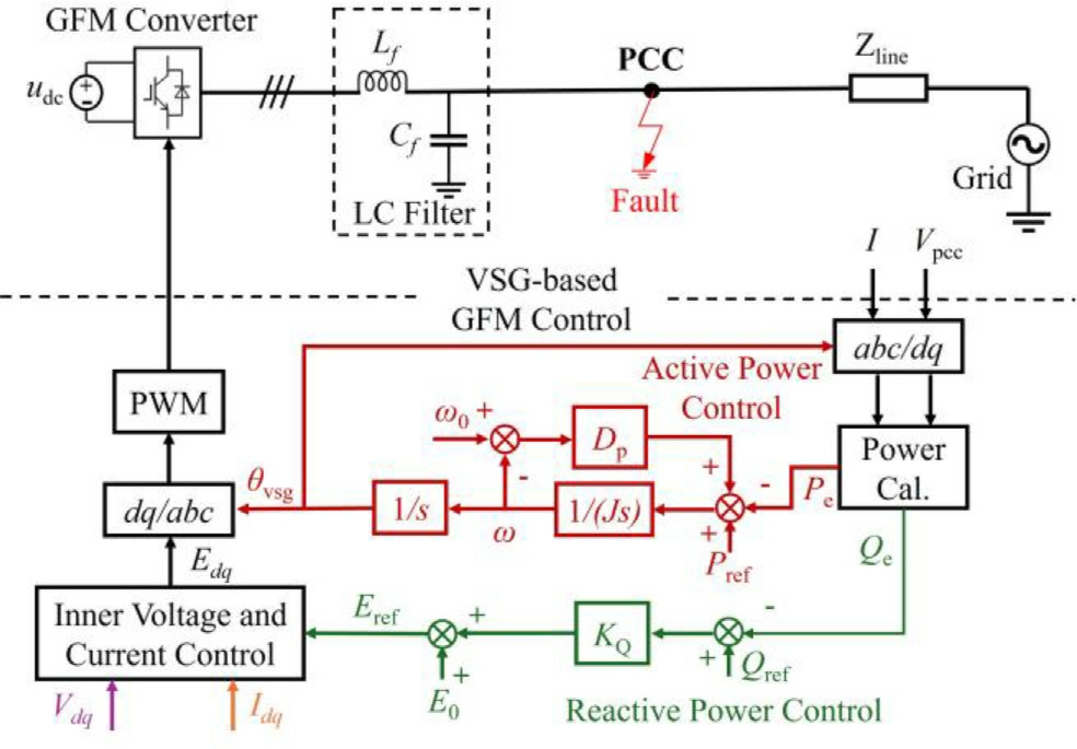
Fig. 1. Configuration of the VSG converter grid-connected system.
The subscripts dq represent the dq-axis of variables. To protect the semiconductor-based converters from overcurrent damage, a circular current limiter marked in red in Fig. 2 is implemented. In this paper, the d-axis prioritybased current limiter is applied, which is universal and easy to use. The current limit er will be activated when Idqref exceeds its pre-set limit Ilim, and can be described as:

1.2 Transient response of VSG converter during grid faults
To better analyze the dynamic response of VSG, the equivalent circuit of the single machine infinite bus system is given in Fig. 3(a). Evsg represents the voltage magnitude of the VSG converter, and the phase angle is θvsg. Ug represents the voltage vector of the grid with phase angle θg.The vector diagram of VSG during the steady state is shown in Fig. 3(b) below.
From Fig. 3(a), the virtual power angle δ is the difference between the phase angle of VSG θvsg and grid θg,which can be expressed as:

During steady state, the active power of VSG can be expressed as:

When a severe grid fault happens, the current vector of the VSG converter reaches the Ilim (typically 1.2 p.u.), and VSG converter behaves as a current source with a constant magnitude.The vector diagram of VSG during current saturation mode is shown in Fig. 4 below.
From Fig. 4, active power under current saturation P cs can be expressed as:

To be noted, when a severe grid fault happens, the VSG converter can easily enter the current saturation and cannot retrieve the power synchronization as a voltage source after the fault is cleared.To better illustrate this process,a single VSG converter grid-connected model is built in PSCAD/EMTDC software, similar to Fig. 1, and the dynamic response of VSG converter under severe grid fault is shown in Fig. 5.
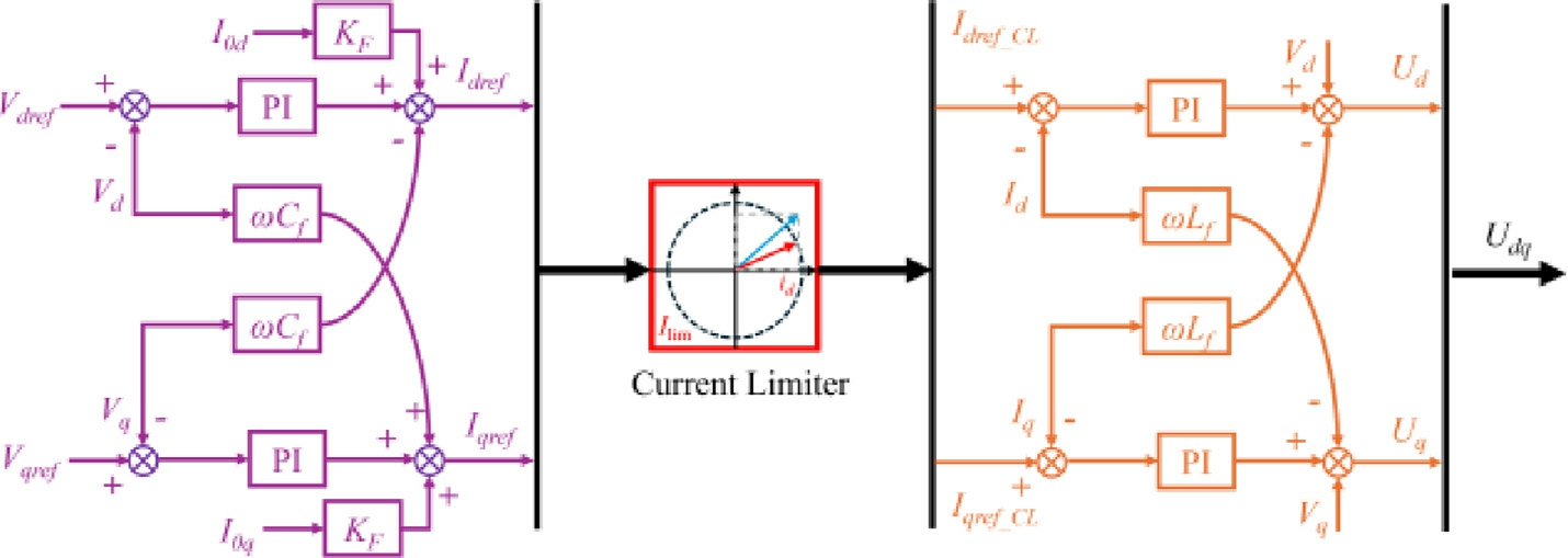
Fig. 2. Inner voltage and current control with current limiter.
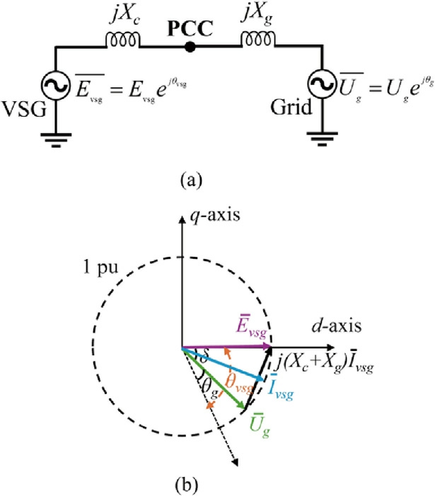
Fig. 3. (a) Equivalent circuit of VSG (b) Vector diagram of VSG during steady state.
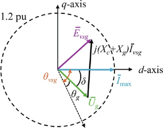
Fig. 4. Vector diagram of VSG in saturated current mode.
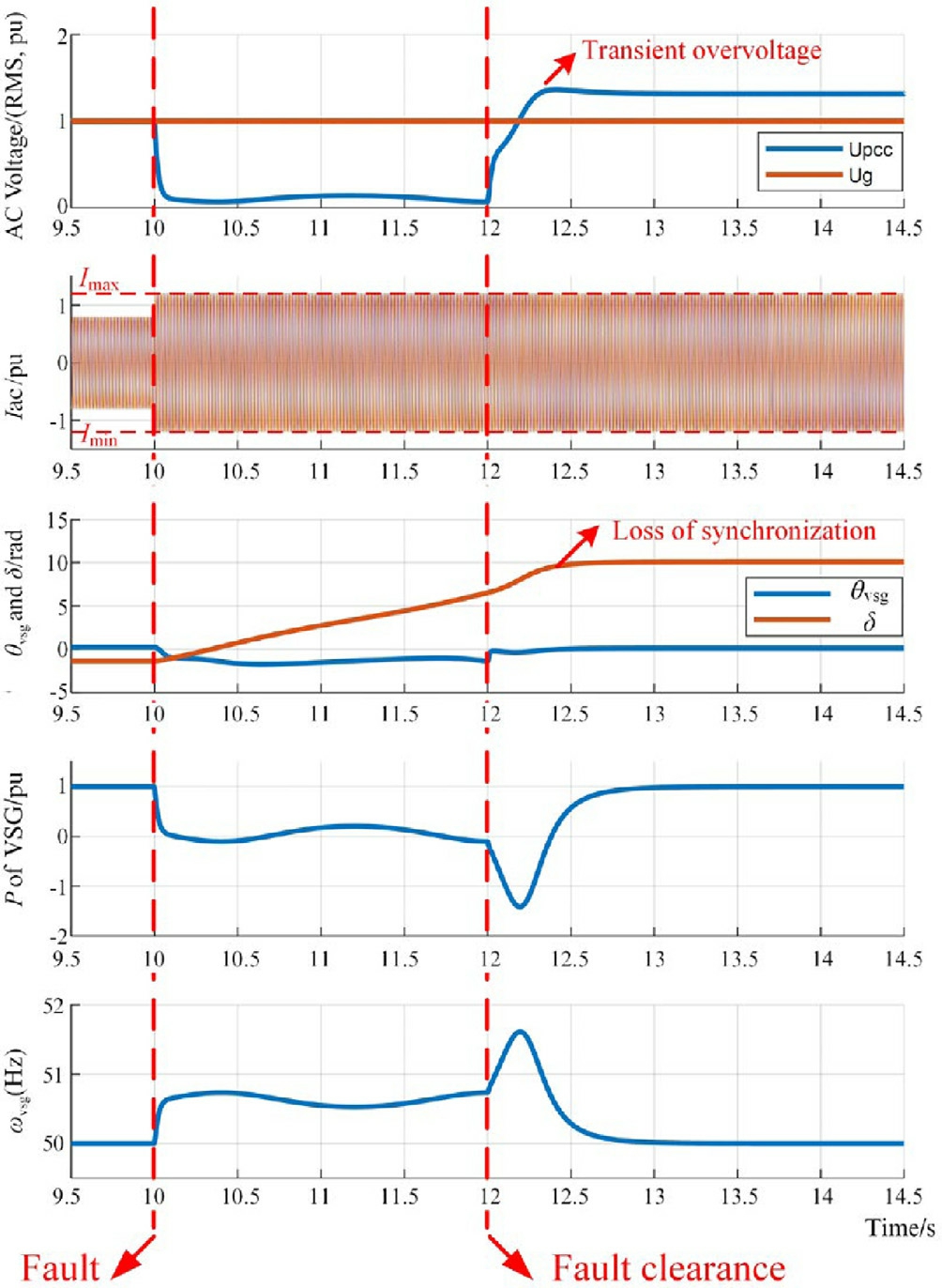
Fig. 5. Dynamic response of the VSG converter under severe grid fault.
The grid code requires that the converter interfaced RES should have the fault ride-through capability with Ug dropping from 1.0 p.u. to 0.2 p.u. an d fault duration time 0.625 s[34]. To emphasize the severe fault, this paper extends the grid code requirement and sets a three-phaseto-ground fault occurring at t = 10 s and clearing at t = 12 s with fault on resistance 0.1 Ω,while Upcc dropping below 0.1 p.u.. As in the analysis mentioned above, from Fig. 5, the Ig,fault reaches the Ilim immediately during the fault, and VSG cannot return to normal voltage control mode. The constant current output of VSG causes serious overvoltage up to 1.363 p.u. after the fault is cleared,which greatly increases the risk of RES tripping. The active power output fluctuates from 1.0 p.u. to 1.41 p.u. even with the strict current limit Imax = 1.2 p.u.. Also,the power angle δ becomes unstable and cannot keep synchronization with the grid, causing the grid transient instability under severe grid fault.
2 Adaptive power and virtual resistance co operative control of VSG converter
In this section, the proposed adaptive power and virtual resistance cooperation based VSG converter control strategy is introduced, which includes the adaptive active power control and the implementation of dynamic virtual resistance.
2.1 Adaptive active power control
The control block diagram of the proposed adaptive active power control is shown in Fig. 6 below.
As the purple and green arrows marked in Fig. 6, during the voltage dip, Pe drops below the Pref due to the dropped Upcc, resulting in the increase in ω and δ, which can also be deduced from (1) and (5). In order to suppress the overcurrent of VSG during severe grid fault considering grid transient stability, the proposed adaptive active power control marked in red in Fig. 6 is added to the Pref.The main idea is to lower the Pref during fault, and a mode selector is implemented, which will shift the active power reference value from pre-set Pnom to Pfault when Upcc drops below 0.9 p.u..The modified adaptive active power control during fault can be expressed as:

where kp and ki are the proportional and integral coeffi-cients in the proportional-integral (PI) controller, respectively; Δδ is the power angle difference, and dΔδ/dt = Δω = ω-ωg, considering ω0 ωg.
As derived from Eq. (7), the change in frequency Δω subsequently leads to a negative dω/dt, initiating a decrease in ω. The ω decline helps to reduce the power angle imbalance Δδ, thereby enhancing the resynchr onization capability of the VSG. Furthermore, the adaptive active power controller lowers the Pref, as compared to the Pref in Eq. (1), to balance the active power difference.A control block diagram of adapti ve active power control is shown below based on Eq. (7):
Compared with the transient stable operatio n of VSG in Eq. (1), Fig. 7 shows that the equivalent damping of VSG increases with the proposed adaptive active power control, which also enhances the transient stability.
The P-δ diagram of VSG converter grid-connected system during fault is shown in Fig. 8 for better illustr ation.
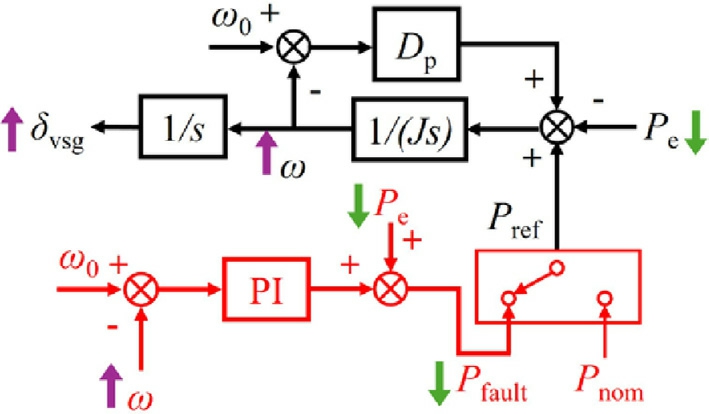
Fig. 6. Control block diagram of the proposed adaptive active power control.
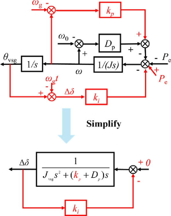
Fig. 7. A simplified control block diagram of the proposed adaptive active power control.
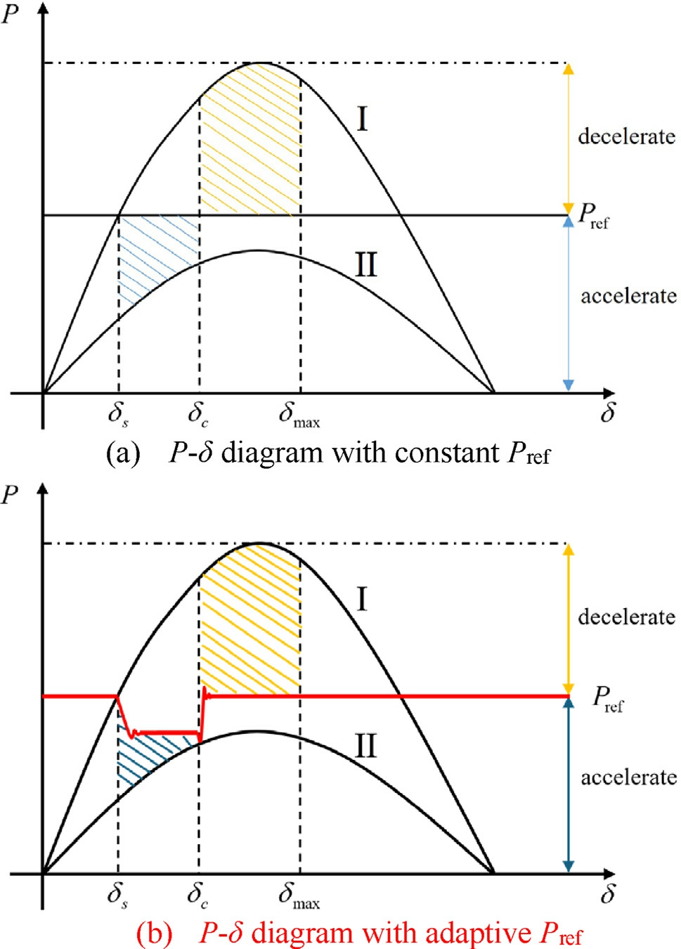
Fig. 8. P-δ diagram of VSG converter grid-connected system during fault through equal area criterion analysis.
From Fig. 8, curve I represents the P-δ relationship of VSG converter grid-connected system before fault and after the fault is cleared, and curve II represents the P-δ relationship during fault. The yellow and blue dashed areas represent the deceleration and acceleration areas,respectively. As the red line shown in Fig. 8(b), the proposed adaptive active power control lowers the Pref during the fault to suppress overcurrent, which also reduces the acceleration area to enhance the grid transient stability.From the above analysis, the adaptive active power control mainly suppresses the imbalance Δδ, balances the active power difference, and enhances the equivalent damping.
2.2 Implementation and design criteria of dynamic virtual resistance
The adaptive active power control can effectively suppress the overcurrent of VSG converter and enhance the grid transient stability. However, the response of ω is relatively slow considering the low bandwidth of the power outer control loop of VSG. The fault current still has the risk of exceeding the limit, especially considering the current overshoot at the moment of fault occurring and clearing.The P-δ diagram with proposed adaptive active power control and Rv is provided in Fig. 9 below.
From Fig. 9(a), during severe fault, when the fault is cleared at ponit a2, the operating point of VSG shifts to a3, which is lower than Pref, resulting in loss of transient stability. For Fig. 9(b), the implementation of adaptive active power control suppresses the rapid increase of δ.After the fault is clear at b2, the operating point shifts to b3 due to the recovery of Upcc, while the δ decreases to the new equilibrium point b4. Also, the proposed dynamic Pref can decrease the acceleration area to enhance the grid transient stability at the same time.
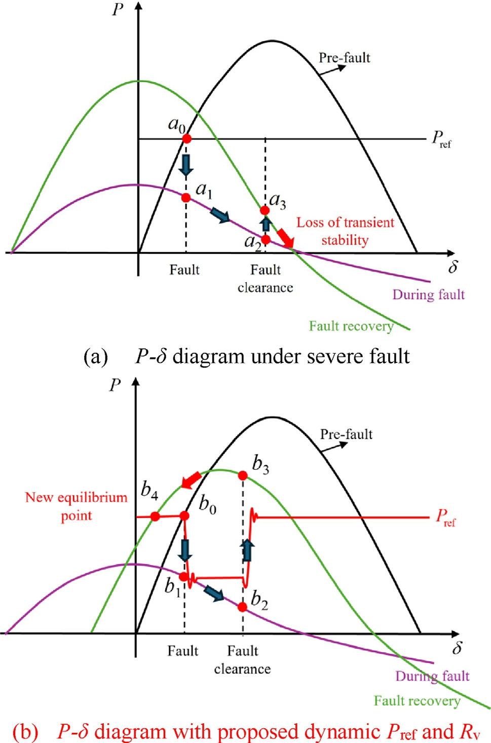
Fig. 9. P-δ diagram of VSG converter grid-connected system during fault with proposed dynamic Pref and Rv.
To better mitigate the overshoot current and keep the grid transient stability, a dynamic virtual resistance Rv is implemented before the inner voltage and current control,as shown in Fig. 10 below.
From Fig. 10, the red marked Rv represents the dynamic virtual resi stance, which can be expressed as:

where Ith is the threshold value of fault current to activate Rv, which is set as 1.05 p.u. in this paper; Kp_vir is the droop coefficient;Kd_vir is the differential coefficient,which can greatly increase the change speed of Rv.
During the fault, the windup in the voltage controller negatively affects the restoration process and hinders the successful exit from current saturation in a VSG. Since the current limiter reduces the signal entering the innercurrent controller, the inverter is unable to inject the necessary current to restore the output voltage to its reference level. As a result, the output voltage remains unregulated,causing the integrator in the voltage controller to continue accumulating error, as illustrated in Fig. 11 below.
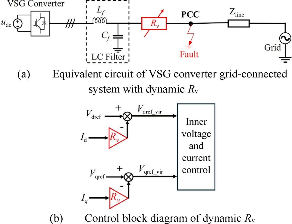
Fig. 10. Implementation of dynamic virtual resistance Rv.
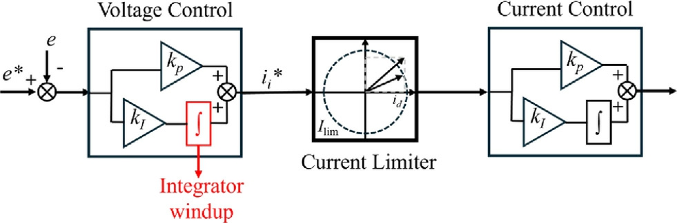
Fig. 11. Windup of the voltage controller during fault.
In this paper, the implementation of virtual resistance helps avoid the windup in the voltage controller. From Fig. 10, functioning as a feedback element, the virtual resistance dynamically lowers the voltage reference in response to the output current,thereby inherently limiting fault current without saturating the inner control loops and thus allowing the VSG inverter to maintain full control independently of the limiter.
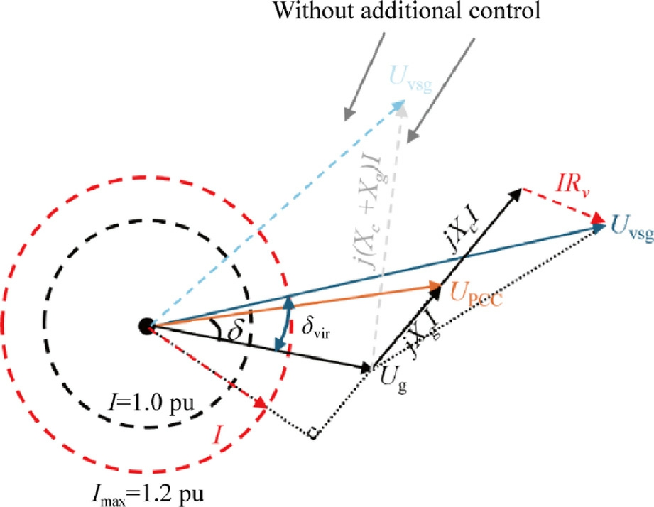
Fig. 12. Vector diagram of VSG with proposed adaptiv e power and Rv cooperation control.
The impact of Rv and proposed adaptive power control on the grid transient stability is shown in Fig. 12 below.
Fig. 12 illustrates the relationship between Uvsg and Ug.From Fig. 12, the virtual power angle δvir increases during fault, which shares the same dynamic behavior as the δ.Compared with the VSG without additional control during fault, as indicated as blue and grey dashed lines in Fig. 12, Δδ is effectively suppressed with the proposed strategy, and the impact of Rv on transient stability is identical to that of grid resistance.
With the virtual resistance, the active power of VSG during fault can be expressed as:

To analyze the effects of Rv, a single VSG converter grid-tied model with Rv is built in PSCAD/EMTDC software, and simulation results with different values of Rv are performed. The voltage dip depth and duration time is set as 0.2 p.u. and 2 s. The Kp_vir ranges from 20 to 0.5 w ith Kd_vir set as 0.1, and the simulation results are shown in Fig. 1 3 below.
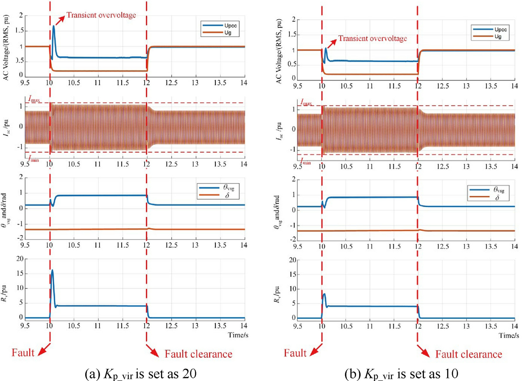
Fig. 13. Dynamic response of the VSG converter under severe voltage dip.
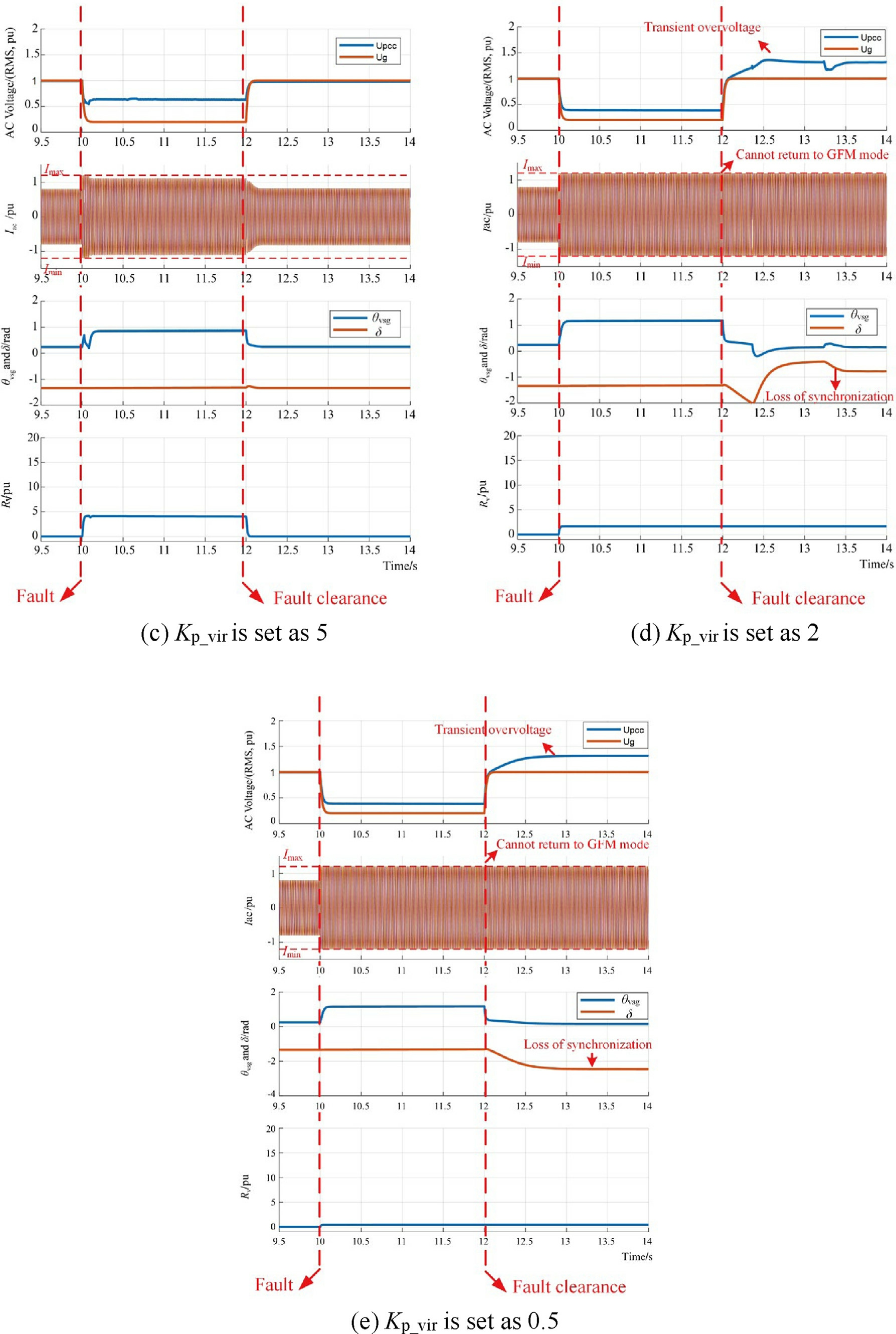
Fig 13. (continued)
From Fig. 13(a)-(c), with the implementation of the proposed dynamic Rv and adaptive power control, under severe voltage dip (Ug from 1.0 to 0.2 p.u.), the grid transient stability is maintained with VSG converter connected, and the overcurrent of VSG converter is effectively suppressed when Kp_vir is set as 20, 10, 5,respectively.
However, the greater Kp_vir brings serious transient voltage overshoot when the fault occurs, as shown in Fig. 13(a) and (b), and the value of Rv approaches a stable value around 4.15 during the fault condition. For Kp_vir sets at smaller values,as Fig. 13(d) and (e), the loss of grid transient stability appears and the current saturation jeopardizes the synchronization of VSG converter, which acts as a current source with constant magnitude and cannot return to voltage-controlled mode even when the fault is cleared. Fig. 14 shows the Rv with different settings of Kp_vir and K d_vir to better illustrate their effects.
From Fig. 14(a), the larger setting of Kp_vir brings a significant overshoot of Rv when the fault happens. And Rv will reach a steady value no matter whether Kp_vir is set as 5, 10, or 20. However, the smaller setting of Kp_vir, such as setting at 2 or 0.5, will limit the performance of Rv,which cannot effectively improve the grid transient stability and overcurrent suppression of VSG converter. From(9), the dynamic response of VSG converter is also related to Rline and Xline. In this paper, those two parameters are assumed to be known. Based on the above analysis, Kp_vir is set as 5 in this paper, which can enhance the grid transient stability and suppress the overcurrent of VSG converter during severe fault, without causing overshoot of Rv and transient overvoltage as well.
From (8), another influencing factor of Rv is Kd_vir. To analyze the effect of Kd_vir, the same simulation is performed with different values of K d_vir, and Kp_vir is set as 5 with voltage dip depth and duration time setting as 0.2 p.u. and 2 s.
From Fig. 14(b), the Kd_vir, only affects the ramping speed of Rv. To be noted, a larger value of Kd_vir limits the performance of dynamic Rv, which will jeopardize the grid transient stability. And a too small setting of Kd_vir will enlarge the overshoot. To balance the pros and cons, Kd_vir is set as 0.1 in this paper for severe fault.
3 Simulation validati on
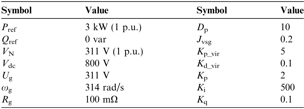
To validate the effectiveness of the proposed adaptive power and virtual resistance cooperation control strategy of VSG converter for grid transient stability enhancement,the simulations based on PSCAD/EMTDC so ftware are performed in this section. The simulation system is the same as the single VSG converter grid-tied system shown in Fig. 1. The main simulation pa rameters are listed in Table 1 below.
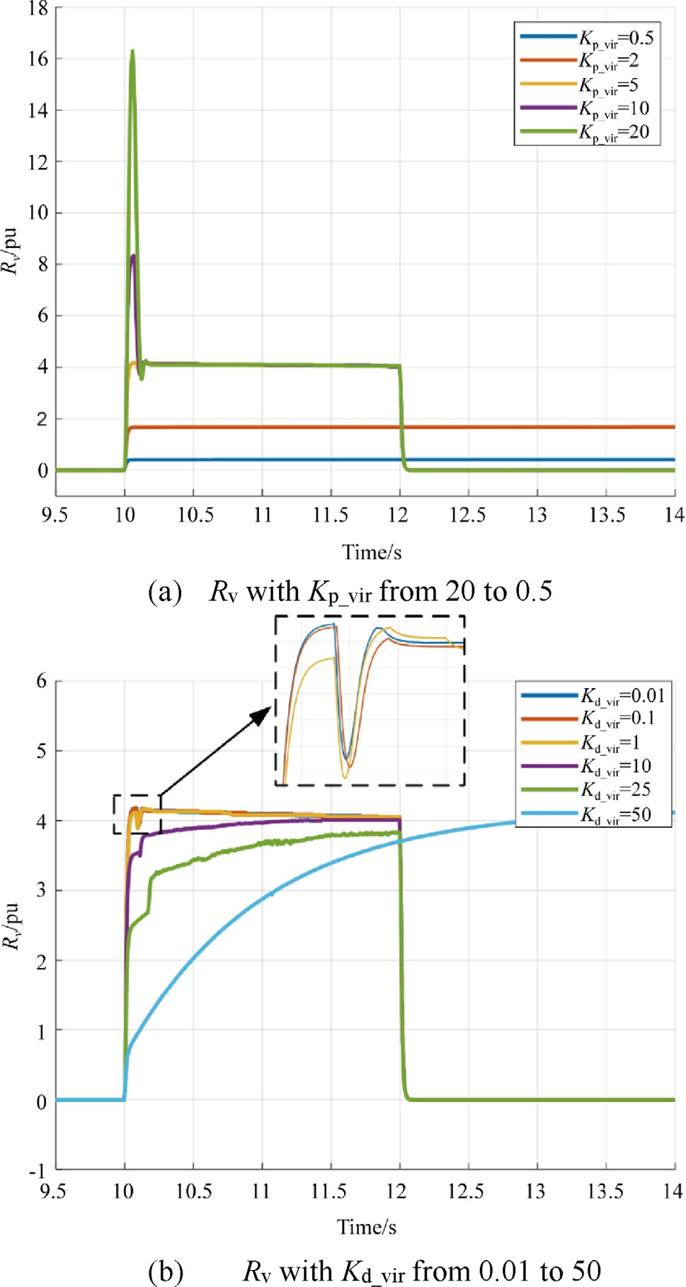
Fig. 14. Dynamic Rv with different settings of Kp_vir and Kd_vir.
Table 1 Main parameters in single VSG converter grid-tied system.
3.1 Simulation results of the proposed control strategy under different fault conditions
Fig. 5 discussed i n Section 1. 2 shows the dynamic response of VSG converter without additional control under severe fault. In that case, the single VSG converter grid-tied system loses transient stability and cannot retrieve GFM mode after the fault is cleared, which also brings serious overvoltage.
In compariso n, Fig. 15(a) and (b) show the dynamic response of VSG converter with the proposed control strategy under moderate (fault on resistance set as 1 Ω with fault duration time 0.5 s) and severe faults (fault on resistance set as 0.1 Ω with fault duration time 2 s). The simulation results demonstrate that the proposed control strategy can effectively suppress the overcu rrent during fault and avoid transient overvoltage after fault clearance.Pref and Rv can adaptively change their values based on the fault depth and duration time. Also, δ can keep synchronization with the proposed control and maintain GFM mode in different fault conditions.
To better illustrate the correctness of theoretical analysis in Section 2 and the effectiveness of propo sed control strategy, Fig. 1 6 shows the simulation results for the P-δ diagram of VSG converter under severe faults without additional control and with proposed control.
The dot labels in Fig. 16 (a0-a2 and b0-b4) are the same as the ones in Fig. 9. As shown in Fig. 16, the theoretical anal ysis in Section 2 is consistent with the simulated results. Also, the proposed control strategy of VSG converter can effectively enhance the transient stability under severe fault by limiting the rapid increase of δvsg. Δδ represents the power angle difference of VSG converter between the fault occurring and fault clearing,which can be expressed as:

where δclear is the power angle of VSG converter when the fault is cleared, and δ 0 is the initial power angle of VSG converter before the fault.
From the theoretical analysis in Fig. 8 and Fig. 9, the extended equal area criterion dictates that the acceleration area should not surpass the deceleration area to maintain transient stability, which can be expressed as:

Eq. (11) indicates that reducing the acceleration area is a direct approach to enhancing the transient stability margin of the system. From Eq. (9), the dynamic selection of the Pref and Rv during grid fault enables the reduction of Δδ. Combined with the adaptive active power control which lowers the Pref during the fault,the acceleration area is further reduced to enhance the grid transient stability.
From Fig. 16, Δδ is 7.891 without additional control of VSG converter. For comparison, with the same fault depth and duration time (severe fault), Δδ is limited to 0.024 with the proposed control stra tegy, which shows that the simulation results also demonstrate the effectiveness of the proposed control in terms of transient stability enhancement.
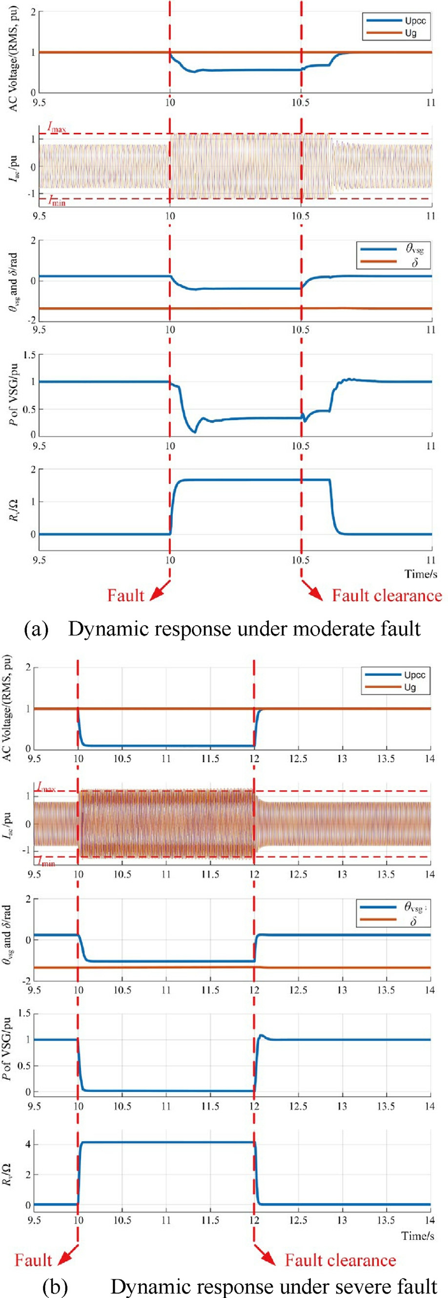
Fig. 15. Dynamic response of VSG converte r under moderate and severe faults.
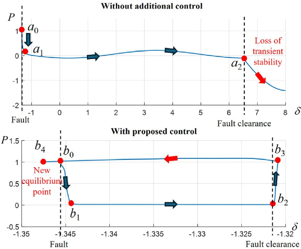
Fig. 16. P-δ diagram of VSG converter under severe fault.
Fig. 17 below presents phase portraits that intuitively depict the relationship between the power angle δ andδ under different fault conditions with and without the proposed strategy, serving as a visual tool for analyzing transient stability and further validating the simulation results.
3.2 Comparison with existing control strategies
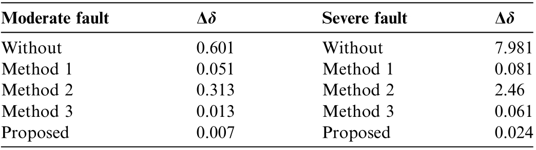
Fig. 18 and Fig. 19 show the comparisons of the proposed control with existing control strategies, including the power compensation control (referred as method 1)[14], virtual impedance optimization (referre d as method 2) [21], and active power and voltage cooperative control(referred as method 3) [33], under moderate and severe faults (same fault settings as Fig. 15), respectively. More details of the compared strategies are listed in Appendix.To qualify the enhancement of proposed control in terms of transient stability,Table 2 compares the Δδ of different control strategies in both moderate and severe faults.
As shown in Fig. 18 and Table 2, under moderate fault(fault on resistance set as 1 Ω with fault duration time 0.5 s), existing method 1 and 3 can suppress the overcurrent and δvsg when the fault happens. Although method 1 can suppress the θvsg and δvsg during fault, it cannot retrieve the converter from overcurrent saturation and causes transient overvoltage after the fault is cleared.Method 3 and the proposed control show great performance in overcurrent suppression while enhancing grid transient stability under moderate fault.
As shown in Fig. 19, under severe fault (fault on resistance set as 0.1 Ω with fault duration time 2 s),the existing methods all lose stability in different ways. From Table 2,δvsg changes sharply for methods 2, which cause serious grid transient instability. Method 1 and 3 shows better performance in grid transient stability enhancement during fault. But, the current saturation of method 1 and 3 alters the VSG converter to a constant current source, and cannot be retrieved back to GFM mode after the fault is cleared. In comparison, the proposed method can effectively suppress both the overcurrent and the transient overvoltage. Also, the risk of grid transient instability is eliminated to keep synchronization with the grid during severe fault condition.
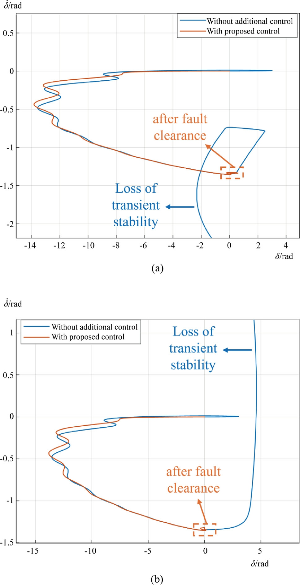
Fig. 17. Phase portrait of VSG converter (a) under moderate fault and(b) under severe fault.
3.3 Simulation results of the proposed strategy in modified IEEE 9 bus systems
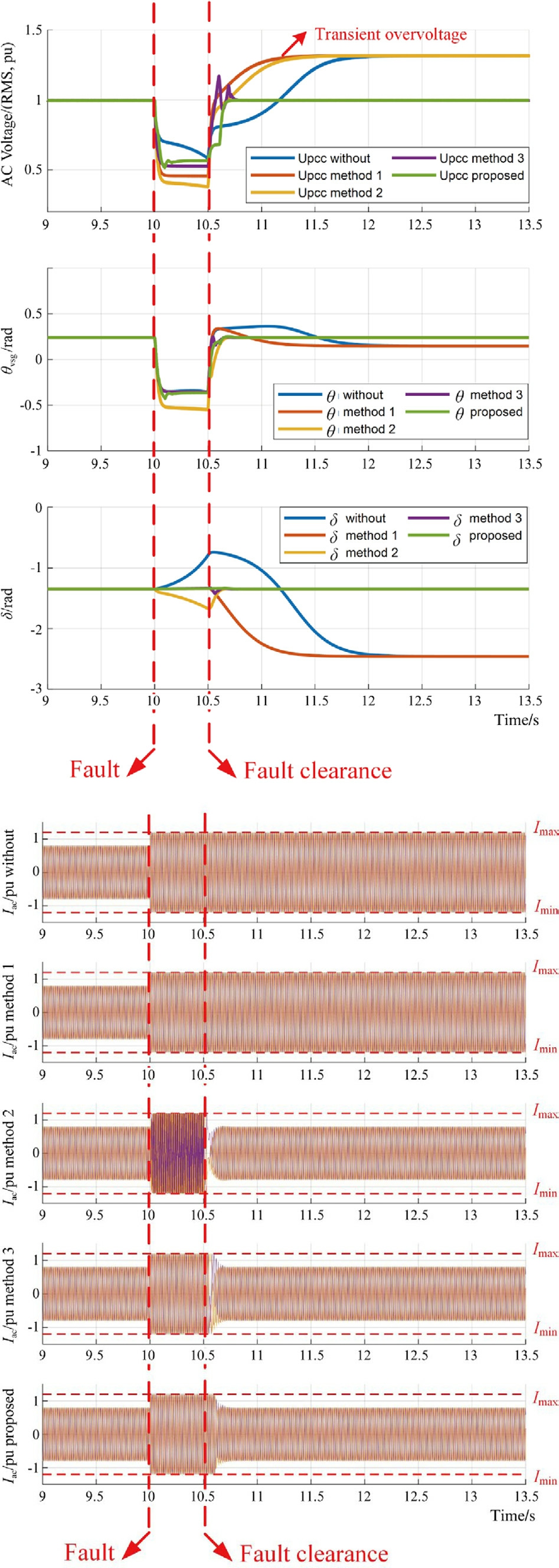
Fig. 18. Comparison of proposed control with existing methods under moderate fault.
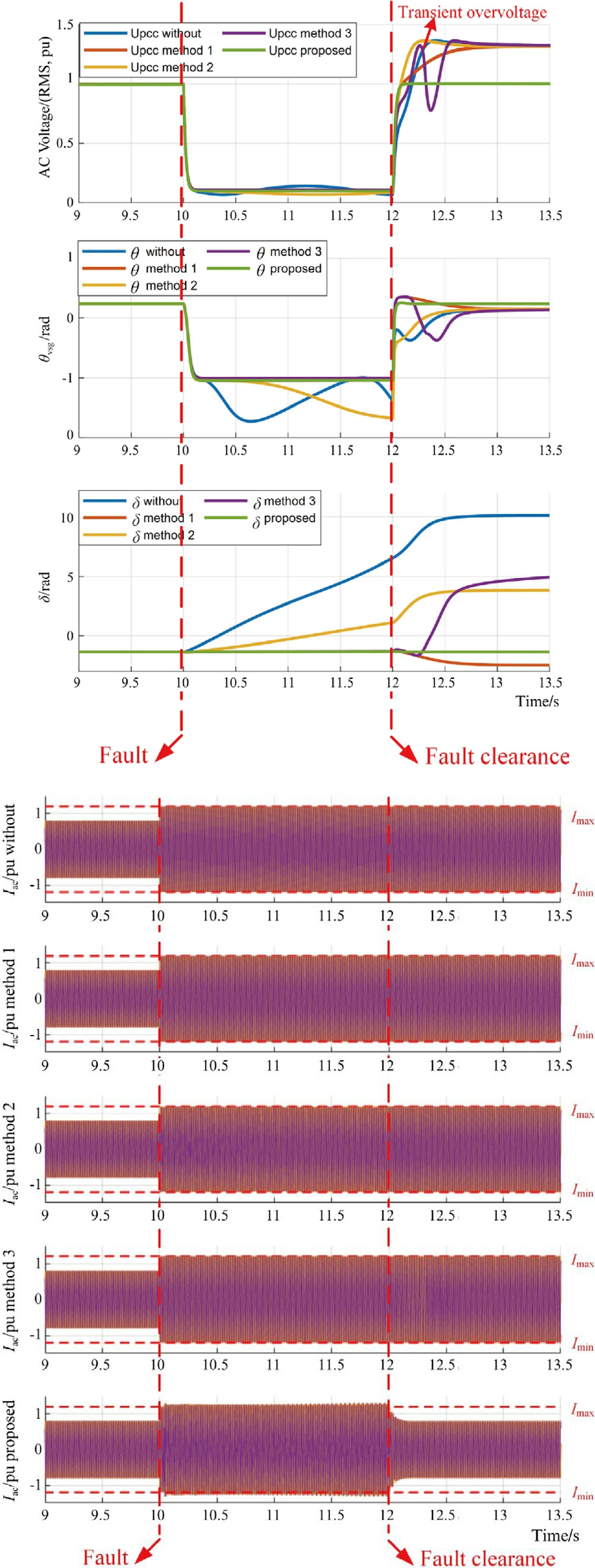
Fig. 19. Comparison of the proposed control with existing methods under severe fault.
Table 2 Comparison of proposed control with existing methods for Δδ under moderate and severe faults.
To further verify the effectiveness of the proposed strategy in multi-machine systems, a modified IEEE 9 bus system is conducted on the PSCAD/EMTDC platform. In this system, Source 3 is configured as a VSG-based GFM converter, with its active power reference set to Pref = 100 MW. Synchronous generators G1 and G2 are represented by a standard second-order model. All other system parameters remain consistent with the standard IEEE 9 bus system. The corresponding topology and control parameters are provided in Fig. 20 and Table 3 below.
From Fig. 20, a three-phase-to-ground fault happens at bus 6, with fault on resistance set as 0.01 Ω and fault duration time 0.2 s(from 10 s to 10.2 s).Fig. 21(a) and (b) show the dynamic response of VSG converter without additional control and with the proposed control strategy,respectively.
From Fig. 21(a), the excessive increase of phase angle during fault causes the non-existence of equilium point after fault clearance, and the loss of synchronization happens, which is consistent with the analysis shown in Fig. 9(a). Also, the VSG converter enters the current saturation immediately during the fault, and is locked in saturation even after the fault clearance. For comparison, as shown in Fig. 21(b), the proposed control strategy ensures transient stability during fault ride-through by effectively mitigating the abrupt changes in power angle and balancing active power. Furthermore, the dynamic virtual resistance suppresses overcurrent, prevents voltage control loop windup, and ensures transition from current saturation back to voltage control mode once the fault is cleared.
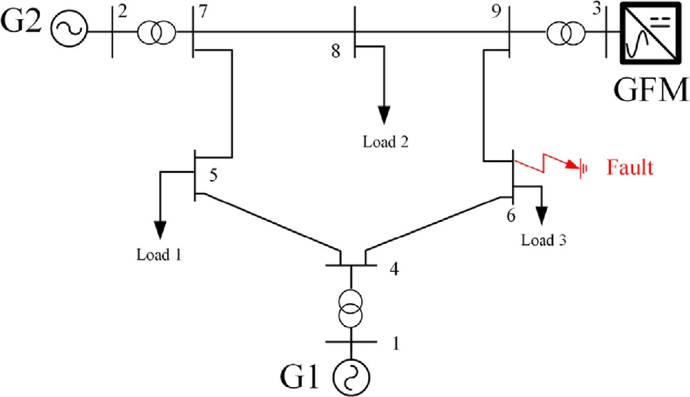
Fig. 20. Configuration of the modified IEEE 9 bus system.
Table 3 Main parameters in modified IEEE 9 bus system.
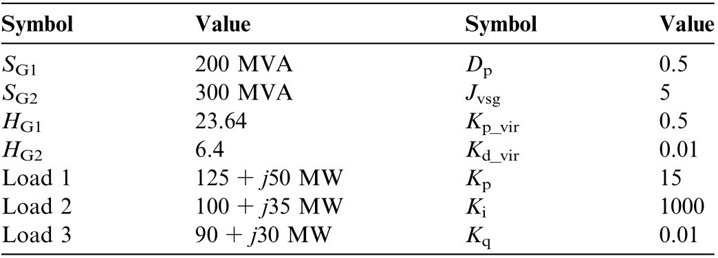
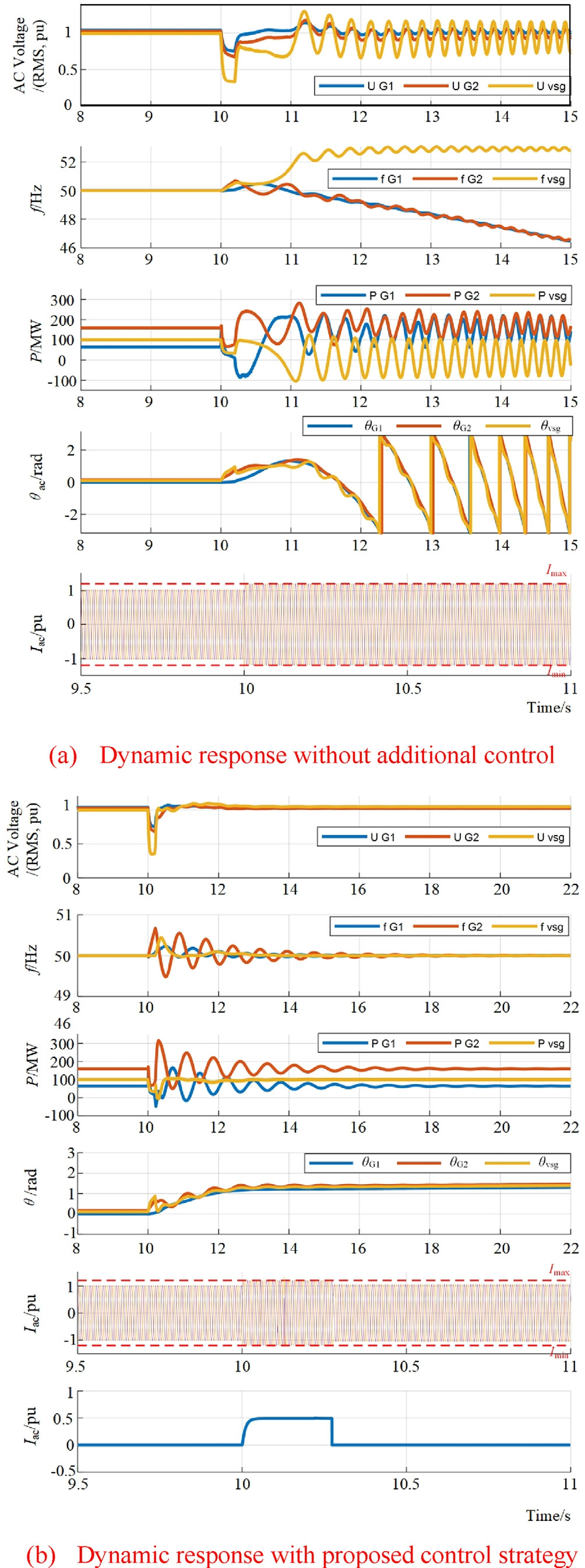
Fig. 21. Dynamic response of VSG converter under faults.
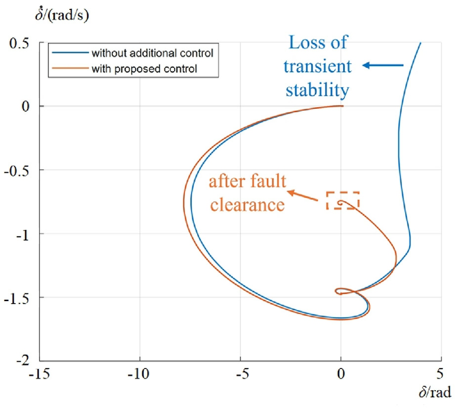
Fig. 22. Phase portrait of VSG converter during fault.
To better visually illustrate the transient stability of VSG converter during fault, Fig. 22 provides the phase portrait of VSG without additional con trol and with proposed control strategy. Fig. 22 shares the same resul ts as Fig. 21, and further demonstrates the transient stability enhancement of the prop osed control strategy in modified IEEE 9 bus systems.
4 Conc lusions
GFM control of converters is one of key technologies for transient stability enhancement of future power electronic converter-dominated power grids. In this paper,the two key problems faced by VSG GFM converter during grid fault are studi ed:the overcurrent of the VSG converter and grid transient instability of the VSG converter connected. Specifically, the main contributions are outlined as follows:
1) The adaptive active power control reveals the relationship between angular frequency and active power reference of VSG converter. The appropriate setting of power reference during grid fault can enhance the grid transient stability by reducing the acceleration area,while suppressing the overcurrent of VSG converter.
2) The implementation of virtual resistance can effectively suppress the overcurrent and potential voltage windup of the VSG converter during fault recovery.The implementation of dynamic virtual resistance adjusts the value based on the fault current, which not only eliminates the current overshoot of the VSG converter at the moment of fault occurring and clearing, but also ensures the successful transition from current saturation back to voltage control mode after the fault clearance.
3) The proposed adaptive power and virtual resistance cooperation control strategy gives full play to the reactive power support capability of the VSG converter and effectively boosts the voltage at the PCC point under both moderate and severe faults. The theoretical analysis and simulation validations demonstrate the effectiveness and robustness of the overcurrent suppression of the VSG converter while enhancing the grid transient stability under different fault depths and duration times by the proposed control strategy.
For future works, the ratio of GFL converters and GFM converters under different application scenarios in future power electronic converter-dominated power grid will be further discussed, and the interactions between GFL and GFM convert ers for parallel-connected multiconverter systems in terms of grid transient stability enhancement and fault ride-through improvements will be further considered.
CRediT authorship contribution statement
Zhang Wen: Writing - original draft, Software,Methodology, Investigation, Formal analysis, Conceptualization. Liangzhong Yao: Writing - review & editing,Supervision, Project administration. Fan Cheng: Validation, Methodology. Shuai Liang: Softw are, Methodology.Junpeng Deng: Formal analysis, Data curation. Siyang Liao: Validation, Project administration. Beilin Mao:Supervision, Project administration.
Declaration of competing interest
The authors declare the following financial interests/personal relationships which may be considered as potential competing interests: Liangzhong YAO reports financial support was provided by Wuhan University. If there are other authors, they declar e that they have no known competing financial interests or personal relationships that could have appeared to influence the work reported in this paper.
Acknowledgments
This research is supported by National Natural Science Foundation of China (Grant No. U23B6007, Fundamental Theory and Methods for Form Evolution and High Efficient Safe Operation of New Power Distribution Systems).
Appendix
The control block diagrams of the compared strategies are shown in Fig. A1 below.
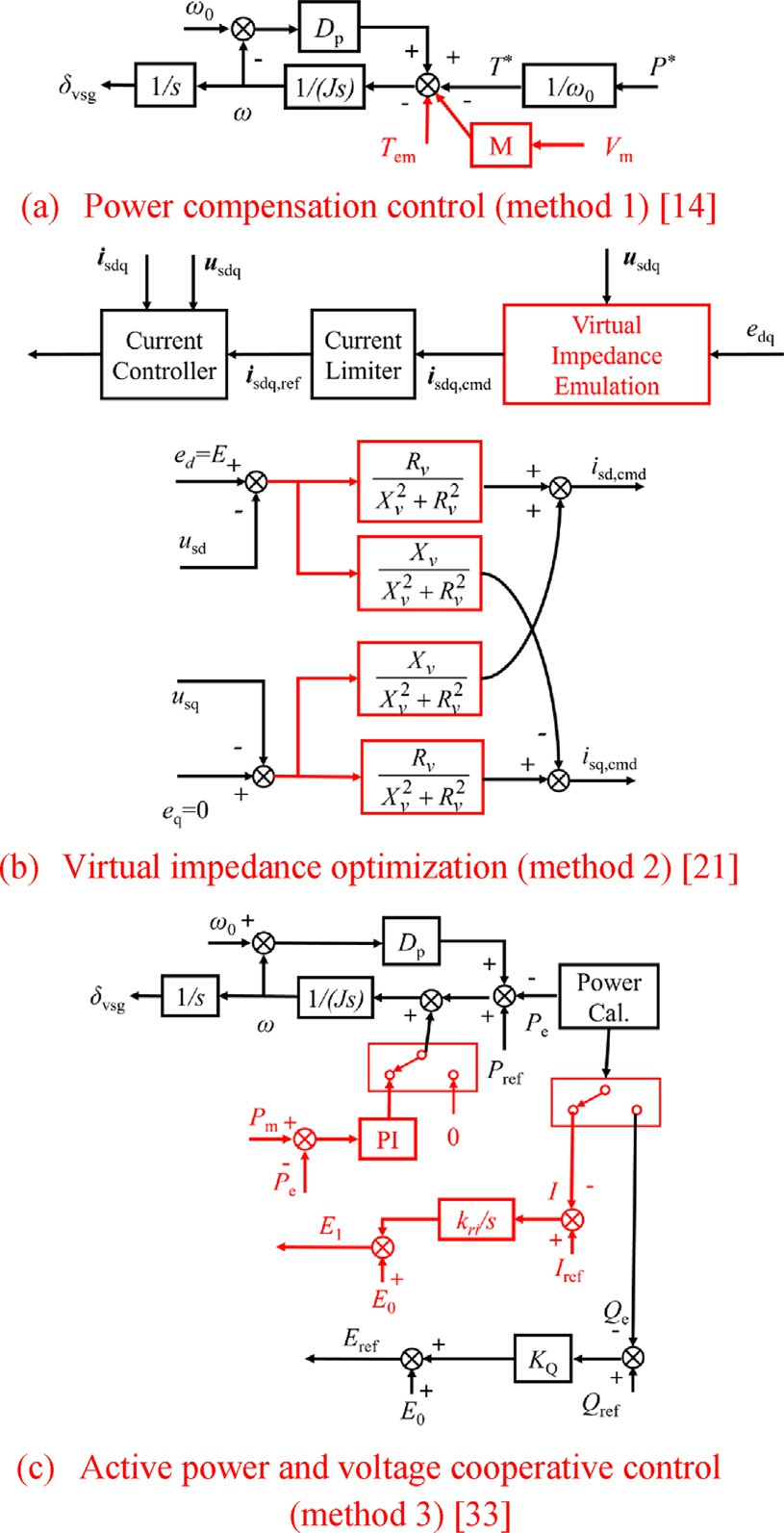
Fig. A1. Control block diagram of the compared strategies.
From Fig. A1 above, for power compensation control(method 1), the power compensation ΔT is given as:

where Vg is the amplitude of the grid voltage; Vrated represents the rated voltage magnitude; M can be calculated by M = ΔT/ΔV. More detailed parameters can be found in[14].
For virtual impedance optimization (method 2), a quasi-stationary virtual impedance is proposed:

More detailed parameters can be found in [21].
For active power and voltage cooperative control(method 3), the modified active power control can be expressed as:

where the voltage control is integrated based on the current difference between Iref and I. More detailed parameters can be found in [33].
References
[1]Z. Zhang, C. Kang, Challenges and prospects for constructing the new-type power system towards a carbon neutrality future [J],Proc. CSEE 42 (08) (2022) 2806-2819.
[2]K. Strunz, K. Almunem, C. Wulkow, et al., Enabling 100%renewable power systems through power electronic grid-forming converter and control: system integration for security,stability,and application to Europe [J], Proc. IEEE 111 (7) (2023) 891-915.
[3]S. Liang, L. Yao, J. Xu, et al.,Power system transient stability limit enhancement method based on virtual synchronous grid-forming control of power electronic converters [J], Proc. CSEE 45 (08)(2025) 2911-2925.
[4]Y. Teng, W. Deng, W. Pei, et al.,Review on grid-forming converter control methods in high-proportion renewable energy power systems [J], Global Energy Interconnect. 5 (3) (2022) 328-342.
[5]J. Rocabert, A. Luna, F. Blaabjerg, P. Rodrı´guez, Control of power converters in AC microgrids [J], IEEE Trans. Power Electron. 27 (11) (2012) 4734-4749.
[6]Z. Wen, L. Yao, F. Cheng, et al.,A comprehensive review of wind power based power system frequency regulation[J], Front.Energy 17 (5) (2023) 611-634.
[7]M. Chen, D. Zhou, A. Tayyebi, E. Prieto-Araujo, F. Do¨rfler, F.Blaabjerg, Generalized multivariable grid-forming control design for power converters [J], IEEE Trans. Smart Grid 13(4)(July 2022)2873-2885.
[8]B.B. Johnson, S.V. Dhople, A.O. Hamadeh, P.T. Krein,Synchronization of parallel single-phase inverters with virtual oscillator control [J], IEEE Trans. Power Electron. 29 (11) (2014)6124-6138.
[9]B. Fan, T. Liu, F. Zhao, H. Wu, X. Wang, A review of currentlimiting control of grid-forming inverters under symmetrical disturbances [J], IEEE Open J. Power Electron. 3 (2022) 955-969.
[10]K.G. Saffar, S. Driss, F.B. Ajaei, Impacts of current limiting on the transient stability of the virtual synchronous generator [J], IEEE Trans. Power Electron. 38 (2) (2023) 1509-1521.
[11]K. Gao, F. Xiao, P. Ge, C. Tu, K.Zou,Z.Xiao,Transient stability interval analysis of a virtual synchronized generator considering fault current limitation [J/OL], Power Syst. Technol. (2025) 1-11.
[12]S. Liemann, C. Rehtanz, Voltage stability analysis of grid-forming converters with current limitation [J], Electric Power Syst.Res.235(000) (2024) 8.
[13]N. Baeckeland, D. Chatterjee, M. Lu, B. Johnson, G.-S. Seo,Overcurrent limiting in grid-forming inverters: a comprehensive review and discussion [J], IEEE Trans. Power Electron. 39 (11)(2024) 14493-14517.
[14]Z. Shuai, C. Shen, X. Liu, Z. Li, Z.J. Shen, Transient angle stability of virtual synchronous generators using Lyapunov’s direct method [J], IEEE Trans. Smart Grid 10 (4) (July 2019)4648-4661.
[15]B. Long, C. Hu, Z. Chen, J. Hu, J. Rodrı´guez, Transient stability analysis and virtual power compensation of a virtual synchronous generator under low-voltage fault [J], IEEE Trans.Power Electron.39 (10) (2024) 12803-12814.
[16]P. Ge, C. Tu, F. Xiao, Q. Guo, J. Gao, Design-orient ed analysis and transient stability enhancement control for a v irtual synchronous generator [J], IEEE Trans. Ind. Electron. 70 (3)(2023) 2675-268 4.
[17]X. Li et al., Transient stability analysis for grid-tied VSG considering high-order nonlinear interactions between active and reactive power control loops [J], IEEE Trans. Power Electron. 39(6) (2024) 6974-6988.
[18]C. Luo, S. Liao, Y. Chen, M. Huang, Quantitative transient stability analysis for parallel grid-tied grid-forming inverters considering reactive power control [J], IEEE Trans. Power Electron. 40 (4) (2025) 4780-4786.
[19]Y. Yang, C. Li, L. Cheng, X. Gao, J. Xu, F. Blaabjerg, A generic power compensation control for grid forming virtual synchronous generator with damping correction loop [J], IEEE Trans. Ind.Electron. 71 (9) (2024) 10908-10918.
[20]L. Huang, C. Wu, D. Zhou, F. Blaabjerg, A power-angle-based adaptive overcurrent protection scheme for grid-forming inverter under large grid disturbances [J], IEEE Trans.Ind.Electron.70(6)(2023) 5927-5936.
[21]Y. Zhang, C. Zhang, R. Yang, M. Molinas, X. Cai, Currentconstrained power-angle characterization method for transient stability analysis of grid-forming voltage source converters [J],IEEE Trans. Energy Convers. 38 (2) (2023) 1338-1349.
[22]X. Qin, C. Fan, L. Qi, et al., Analysis of the essence of grid-forming droop control and the impact of virtual impedance on its source end characteristic [J/OL], Proc. CSEE (2025) 1-14.
[23]S. Chen, Y. Sun, H. Han, S. Fu, S. Luo, G. Shi, A modified VSG control scheme with virtual resistance to enhance both small-signal stability and transient synchronization stability [J], IEEE Trans.Power Electron. 38 (5) (2023) 6005-6014.
[24]L. Zhan, B. Hu, L. Chen, Y. Liao, M. Li, H. Nian, Transient stability enhancement of current limited-GFM inverters based on varying virtual impedance [J], IEEE Trans. Ind. Electron. 71 (12)(2024) 15946-15958.
[25]H. Zhu, L. Shang, Z. Wang, et al., Study on the droop control strategy of grid-forming converters based on fault recovery analysis[J/OL], Power Syst. Technol. (2025) 1-11.
[26]C. Luo, Y. Chen, S. Liao, Z. Wang, Z. Xie, Z. Lian, Designoriented analysis and transient control for VSG with current saturation unit [J], IEEE Trans. Power Electron. 40 (1) (2025)2472-2483.
[27]G. Wang, L. Fu, Q. Hu, C. Liu,Y.Ma,Transient synchronization stability of grid-forming converter during grid fault considering transient switched operation mode [J], IEEE Trans. Sustainable Energy 14 (3) (2023) 1504-1515.
[28]J. Yang, H. Ye, Y. Wang, Y. Liu, Y. Li, Z. Du, Mechanism and methods for fault recovery of grid-forming inverter by graphical illustration [J], IEEE Trans. Power Syst. 40 (2) (2025) 1973-1976.
[29]S.P. Me et al., Transient stability analysis of virtual synchronous generator equipped with quadrature-prioritized current limiter [J],IEEE Trans. Power Electron. 38 (9) (2023) 10547-10553.
[30]K. Zhuang, H. Xin, P. Hu, Z. Wang, Current saturation analysis and anti-windup control design of grid-forming voltage source converter [J], IEEE Trans. Energy Convers. 37 (4) (2022) 2790-2802.
[31]S. Jiang, Y. Zhu, T. Xu, G. Konstantinou, Currentsynchronization control of grid-forming converters for fault current limiting and enhanced synchronizat ion stability [J], IEEE Trans. Power Electron. 39 (5) (2024) 5271-5285.
[32]C. Luo, Y. Chen, Y. Xu, et al., Two-stage transient control for VSG considering fault current limitation and transient angle stability [J], IEEE Trans. Ind. Electron. 71 (7) (2024) 7169-7179.
[33]J. Wang, X. Zhang, Active power and voltage cooperative control for improving fault ride-through capability of grid-forming converters [J], IEEE Trans. Ind. Electron. 71 (10) (2024) 12301-12311.
[34]W. Wang, Y. Chi, Y. Li, et al., Technical Specification for Connecting Wind Farm to Power System—Part 1:On Shore Wind Power[S], Standards Press of China, Beijing, 2021.
Received 7 August 2025; re删vis除ed 30 September 2025; accepted 6 November 2025
Peer review under the responsibility of Global Energy Interconnection Group Co. Ltd.
* Corres删ponding au除thor.
E-mail addresses: wenzhang1996@whu.edu.cn (Z. Wen), yaoliangzhong@whu.edu.cn (L. Yao), chengfan5566@163.com (F. Cheng), liangshuai93@163.com (S. Liang), 13060616029@163.com (J. Deng),liaosiyang@whu.edu.cn (S. Liao), maopeilin@hotmail.com (B. Mao).
https://doi.org/10.1016/j.gloei.2025.11.007
2096-5117/© 2026 Global Energy Interconnection Group Co. Ltd. Publishing services by Elsevier B.V. on behalf of KeAi Communications Co. Ltd.This is an open access article under the CC BY-NC-ND license(http://creativecommons.org/licenses/by-nc-nd/4.0/).

Zhang Wen received the B.S. degree in Electrical Engineering from Rose-hulman Institute of Technology, Indiana, US, in 2018 and the M.S.degree in Electrical Engineering from University of Southern California, California, US, in 2020. He is currently pursuing a Ph.D degree in Electrical Engineering at the School of Electrical Engineering and Automation, Wuhan University. His research interests include largescale renewable energy integration and interaction stability analysis of electronics.