
0 Introduction
Significant advancements in wind turbine performance have been achieved with the introduction of new concepts for maximizing wind energy extraction, such as Diffuser-Augmented Wind Turbines (DAWTs), which have been widely studied for the last two decades. With the addition of a diffuser to a wind turbine, the velocity at the turbine rotor is increased due to the pressure difference, resulting in a performance boost.
According to Vaz and Wood [2], the diffuser is one of the few ways to increase power output, which can be particularly economical in small hydrokinetic turbines. The diffuser effect on wind turbines is commonly studied through blade element theory(BET).Fletcher[3]included diffuser efficiency and area ratio in the BET model.
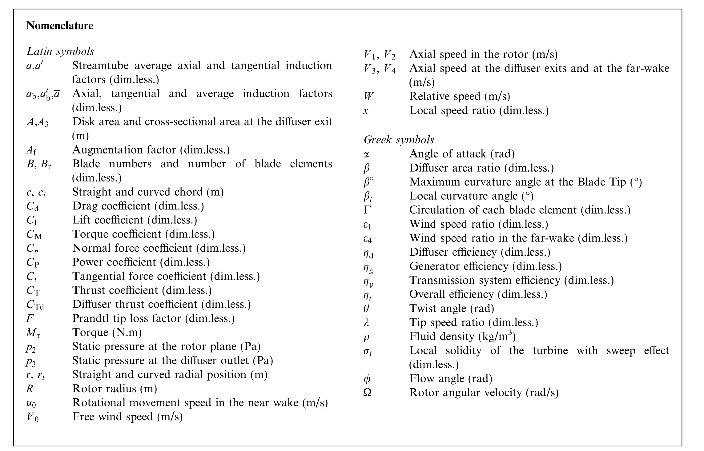
In the classical BET, the energy conversion of a rotor accounts for the torque generated on the blade elements,as shown by Glauert [4]. Fletcher [3] extended the BET model for turbines with diffusers, including wake rotation and the effect of the number of blades.One of the primary reasons for including diffuser efficiency in the analysis of DAWTs is that improved energy extraction is expected to increase the rotation in the expanding wake, thereby transforming axial vorticity in the rotor into circumferential vorticity.This leads to significant positive radial gradients of velocity in the flow direction and eventually to recirculation along the axis, as explained by Batchelor [5].
Glauert[4]significantly contributed to the development of blade element momentum theory(BEMT)by predicting the performance of a wind turbine through the analysis of the forces on the blade elements.He used the combination of energy and momentum conservation principles, along with lift and drag aerodynamic theory.The BEMT is conceptually simple, but highly useful for analyzing the aerodynamics of wind turbines. Over the last two decades,numerous extended BEMT models have been published,including those that account for diffuser effects; however,the authors are unaware of any work that incorporates both diffuser and sweep effects.
Investigating the sweep effect is important due to the following potential benefits: (i) it can significantly reduce the aerodynamic load on the rotor, as reported in Gemaque et al. [6], and (ii) it can increase the power coefficient when the turbine is operating at tip-speed ratios higher than 5.5. Modern turbines typically operate at a tipspeed ratio around 8.0. Furthermore, the sweep effect can assist in mitigating cavitation in hydrokinetic turbines.
Andrade et al. [7] achieved greater chord distributions and twist angles,especially at the blade tips,when optimizing 30°backward swept blades combined with a diffuser,contributing to increased efficiency and the mitigation of cavitation in hydrokinetic turbines. Additionally, Silva et al. [8] developed an appropriate model to avoid cavitation in a hydrokinetic turbine with straight blade. However, they did not discuss an extended model for performance analysis.
Pereira and Vaz [9] implemented a semi-empirical correction for the cascade effect in the BET. Their correction provides an accurate estimation of lift and drag coefficients in various blade sections, allowing for a more precise prediction of the aerodynamic behavior of multibladed rotors. However, it only covers straight blades. Similarly,Sousa et al.[10]analyzed the cascade effect,showing good agreement with experiments, although without sweep.
Barbosa et al. [11] proposed a mathematical model describing internal velocity behavior of conical diffusers.However, thrust and diffuser efficiency were not considered. Borges et al. [12] conducted a statistical analysis and highlighted the importance of proper data treatment in numerical analyses. Dias and Camacho [13] conducted a study using sweep effect on a two-bladed horizontalaxis wind turbine.Both geometries produced higher power coefficients at wind speeds between 10 and 15 m/s compared to a straight blade.As shown in Fig.1,the flow exhibits higher vorticity on the straight blade than on the swept blade (Fig. 1b). It can be concluded that there is an energy loss for the straight blade due to the presence of stronger vortices, and a greater energy utilization of the rotor with swept blade.
Khalafallah et al. [14], Dias and Camacho [13], Nobre et al.[15]and Li et al.[16]obtained good efficiency results with swept blade wind turbines. According to Dias and Camacho [13]’s CFD analysis, the sweep effect increases the efficiency of a wind turbine because the flow exhibits lower vorticity in the swept blade. Therefore, the aerodynamic load on the rotor is relieved, as further described by Pavese et al. [17].
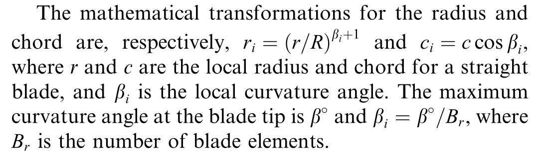
Blade element momentum theory has been extended to include sweep to each radial position of the rotor.Various optimization methods are described in the literature;however, it is not common for these to consider the sweep effect(curved blade).This effect is characterized by the curvature of the blade in the tangential direction, which can be classified as forward sweep when this curvature aligns with the direction of rotation, or backward sweep when the blades are curved in the direction opposite to rotation,as shown in Fig. 2.
The BET model allows for the determination of expressions based on geometry for the forces acting on various sections along the blade. With axial momentum theory(AMT), it is possible to derive expressions related to the flow through conservation of momentum. These unified theories lead to the BEMT, which presents a set of equations that can be solved iteratively. However, these theories require corrections. For example, AMT assumes an infinite number of blades, so the algorithm in this work needs a correction to account for a finite number of blades to better approximate to reality. Additionally, conventional thrust calculations do not align with experimental data for high axial induction factors.Additional corrected equations must also be employed to account for the diffuser efficiency and thrust coefficient in the axial induction factor in the near and far wakes.
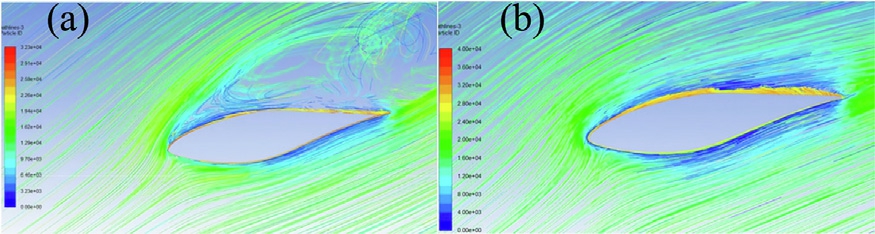
Fig. 1. (a) Vortex on the straight blade (b) vortex on the curved blade.Adapted from Dias and Camacho [13].
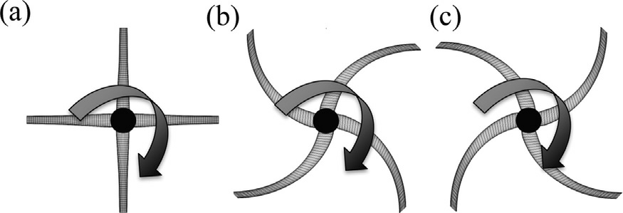
Fig. 2. Swept effect rotors; (a) straight (b) forward and (c) backward.
There are few studies in the literature applied to wind turbines with sweep effect, while most studies focusing on the performance of wind turbines only consider straight-bladed rotors. In this context, a new approach to analyze turbines enhanced by a diffuser with swept blades is proposed.In addition to the power gain provided by the diffuser, the present work introduces a new approach to maximizing the performance (thrust, torque and power)of a DAWT by means of swept blades.Therefore, this work is relevant for the current state of the art,and the authors are unaware of any other work on DAWT performance analysis with swept blades.
This paper is divided into three sections. Section 1 outlines the design parameters and the mathematical models used, with the corresponding expressions. Angular momentum conservation is used to determine the power of the DAWT.Subsection 1.2 presents the main equations of BEMT with a diffuser and explains how to include sweep effect in addition to discussing its theoretical applications. Section 2 presents the results and discussions based on the values obtained from the BEMT model,which will be validated against Hoopen [1]’s experiment.Section 3 addresses the conclusions regarding the sections covered in previous sections and the limitations of the mathematical model used.
1 Methodology
This work presents a novel performance analysis that integrates theoretical principles with experimental data to model the behavior of a DAWT incorporating the sweep effect.The main additions to the BEMT include the sweep effect, the thrust coefficient of the diffuser and the diffuser efficiency. The diffuser efficiency adopted in this work is based on the results of the augmentation factor. The approach includes an approximation for the thrust correction when a wind turbine is surrounded by a diffuser, as well as a formulation for the velocity ratio in the rotor plane and the far-wake.
To analyze the accuracy of the proposed model and to provide evidence of simulation reliability, the diffuseraugmented wind turbine tested by Hoopen[1]is simulated.The primary outcomes of this work are the comparisons of power, torque, and augmentation factor (Af) with the experimental results described in[1].The blade is analyzed and optimized by means of the sweep effect for different curvature angles.
1.1 Analysis parameters
The DAWT designed by the National Aerospace Laboratory(NLR)and analyzed by Hoopen[1]has three blades and a 1.5 m diameter.The diffuser is a circular airfoil with an area ratio of 0.578, and its suction side facing inward. The diameter of the diffuser inlet is approximately 1.52 m, while the diameter of the outlet is 2 m. Hoopen [1] analyzed different diffuser configurations:with a 0.04 m Gurney flap and without vortex generators; without a Gurney flap and with 37 vortex generators of 0.11 m, and without a Gurney flap and vortex generators (simple configuration). The DAWT with a Gurney flap is experimented at a freestream velocity of 10 m/s and a rotation of approximately 716.2 rpm. For Af,Hoopen [1] presented results for wind speeds between 2.5 and 15 m/s. Table 1 shows the data for the DAWT and its operating conditions.Table 1 also shows experimental data for the thrust coefficients of the main diffuser configurations analyzed by Hoopen[1].The value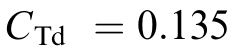 is for comparing the results of Af, while
 is for comparing power and torque. This allows for the assessment of the influence of the diffuser thrust coefficient. Fig. 3 shows the diffuser and rotor configurations.
Fig.4 shows the drag (Cd ) and lift (Cl)coefficients for the NACA 2207 airfoil[1]used in this work.Calculating the ratio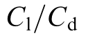 yielded Fig. 4c, which displays the optimal angle of attack for the flow with a Reynolds number of 600,000,based on diffuser diameter. The optimal angle of attack is 2.4°.
Fig. 5 depicts the blade generated from the NACA 2207 airfoil,tested by Hoopen[1].The blade features 42 sections(blade elements). The blade is optimized with sweep effect.
1.2 Blade element momentum theory for swept rotor with diffuser
The axial momentum theory assumes frictionless fluid flow and ignores the rotational velocity component(Fletcher [3], Vaz and Wood [2]). In order to model a diffuser with losses and sweep effect, it is necessary to consider an approach for determining the flow in a duct, as well as mathematical expressions to transform radial and chord coordinates. The axial momentum theory with a curved radius, considering the rotational velocity component, is shown in Fig. 6. In this case, the sweep effect is applied only to the radial position.
Table 1
Project parameters.
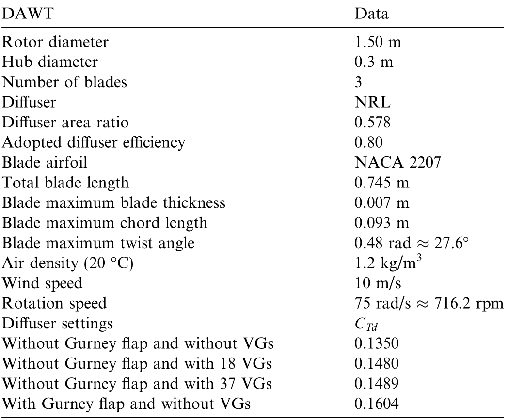
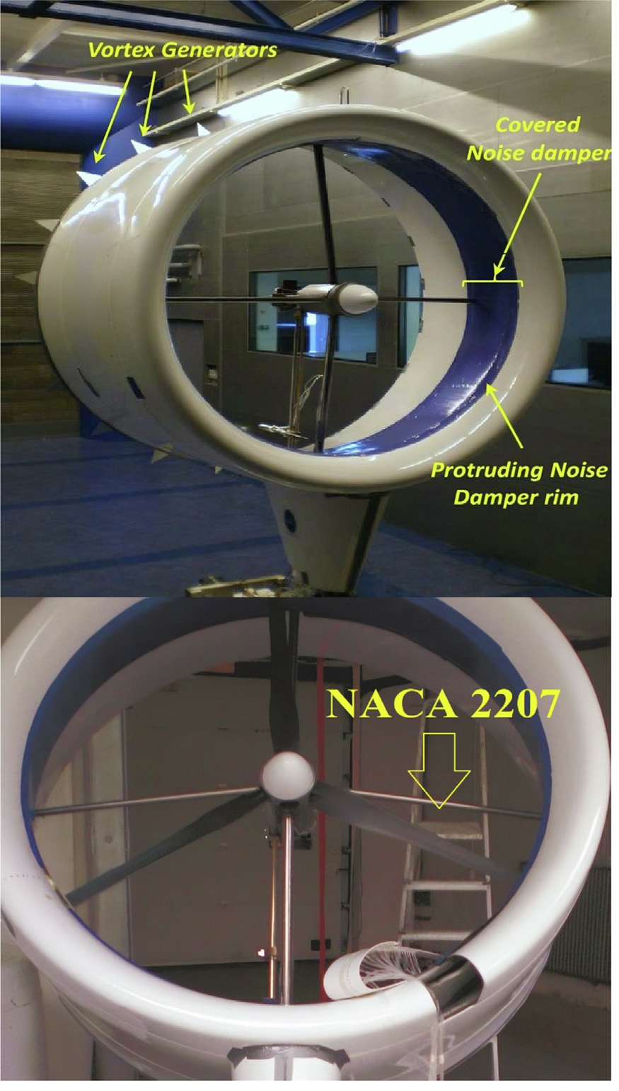
Fig. 3. Experimental diffuser-augmented wind turbine (DAWT).Adapted from Hoopen [1].
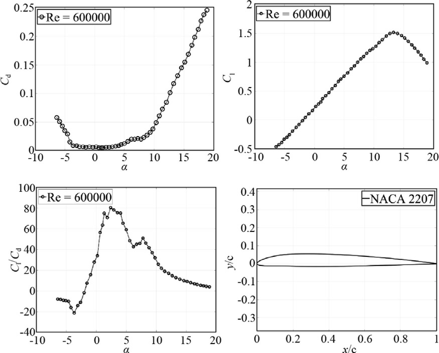
Fig.4. NACA 2207 airfoil aerodynamic data.Adapted from Hoopen[1].
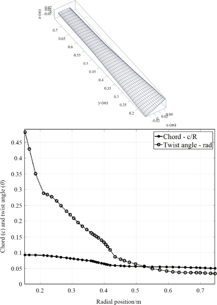
Fig. 5. Blade, chord, and twist angle. Adapted from Hoopen [1].
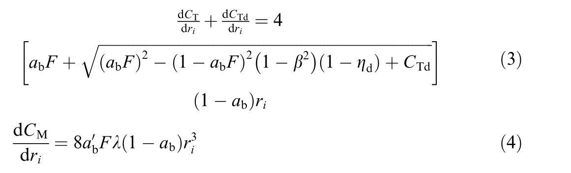
The elemental thrust and torque coefficients in the annular control volume(Fig.6)are determined using the principle of angular momentum conservation. Considering the transformed radius r i(m),the elemental thrust and torque coeffi-cients become(Wood and Okulov[18],Vaz and Wood[19]):
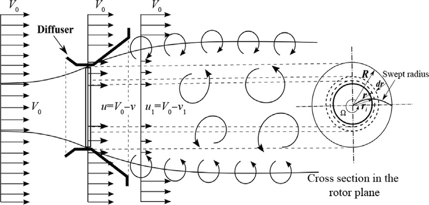
Fig. 6. Control volume with sweep effect and diffuser. Adapted from Gemaque et al. [6].

The expression for the tangential velocity in the near wake derived by Wood and Okulov[18]is used to include the effect of the diffuser in the BEMT. Thus, Eqs.(1) and (2) become:
where ηdis the diffuser efficiency, defined in [2] as:

Fig. 7 illustrates the BEMT applied to the rotor with diffuser and swept blades, where cos βiis the main additional term.
The flow angle φ is given by:

The relative velocity(W)and the circulation(Γ)of each blade element are:

where Cl and Cdare the lift and drag coefficients.The normal force coefficient Cnand the tangential force coefficient Ctare:

The formulations for the axial and tangential induction factors considering the sweep effect are given by [20]:
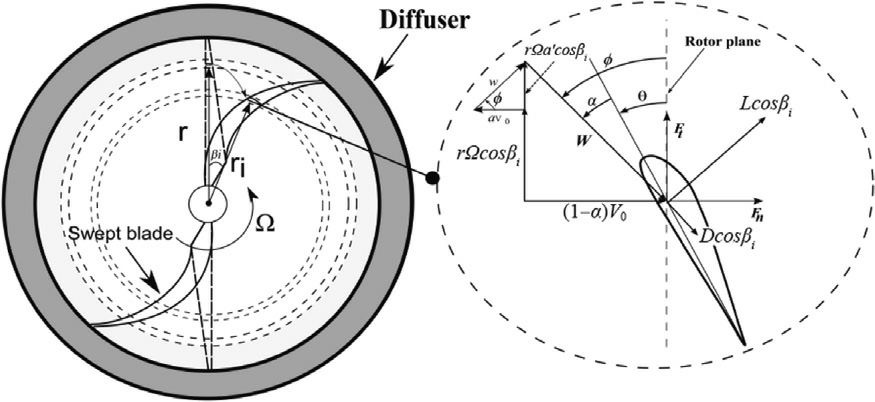
Fig. 7. Radial transformations. Adapted from Gemaque et al. [6].
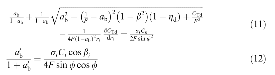
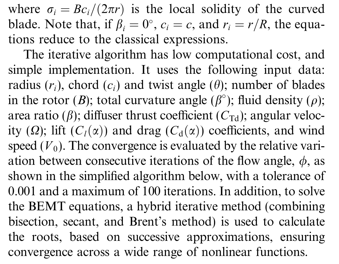
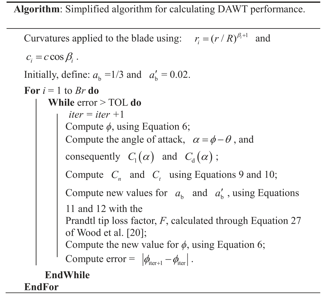
Algorithm 1 (Simplified algorithm for calculating DAWT performance).
It is important to note that several different methods can be used for simulating wind turbine performance, as evidenced in studies conducted by Alipour et al. [21–24].What makes BEMT widely accepted and used by researchers for many years is its balance between accuracy and computational cost, ease of implementation, extensibility for corrections,and extensive validation with experimental data [1–3,6,7,15].
2 Results and discussion
In order to assess the influence of different parameters on the performance of the DAWT, the results of Af, CP,CT,P and Mτare presented for a constant rotation of 716.2 rpm, with variations in CTd, ηdand the sweep effect.
Afresults are collected by varying the sweep effect to determine the optimal blade curvature that maximizes DAWT efficiency.This analysis encompasses both forward sweep (negative angles) and backward sweep (positive angles). The blades are optimized with curvatures of 10°,20°, 30°, and 40°, as shown in Fig. 8. The diameter of the rotors is kept constant at 1.5 m. By applying a sweep to the straight blade and maintaining the original diameter of the rotor, a larger effective linear length of the swept blade is obtained. Thus, by increasing the useful linear length of the blade, its interaction with the airflow can make the aerodynamic load distribution more efficient,making it possible to increase lift and, consequently,torque.
2.1 Augmentation factor
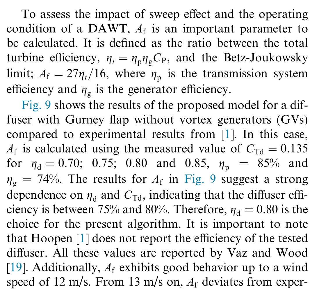
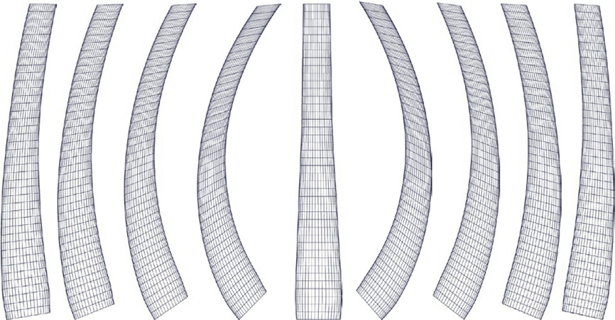
Fig. 8. Blades with backward and forward sweep effect.
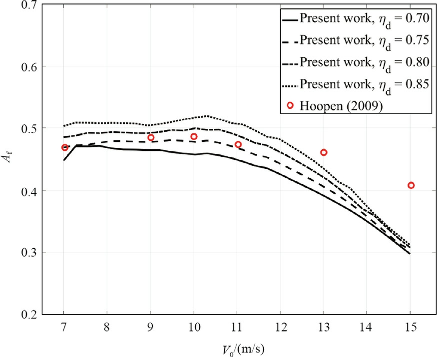
Fig. 9. Estimating the possible efficiency of the diffuser.

Fig. 10 shows the results for Afconsidering the DAWT optimized with forward swept blades. Note that the straight-blade rotor is observed to be in good agreement with the experimental data for wind speeds of 7, 9, 10,and 11 m/s. The performance of the DAWT is analyzed for these wind speeds, as post-stall behavior is not considered. The 10°-curved blade showed an average increase in Afof 0.35% compared to the straight blade, with a maximum Afof 0.499 at 10.18 m/s. The 20°-curved blade demonstrated an average increase of 1.79%in Afcompared to the straight blade, with a maximum Afof 0.507 at 7.86 m/s. The 30°-curved blade showed an average increase of 3.48% in Afcompared to the straight blade,with a maximum Afof 0.518 at 8.15 m/s. The 40°-curved blade exhibited an average increase of 4.90% in Afcompared to the straight blade, with a maximum Afof 0.528 at 7.86 m/s. All sweep angles showed an improvement in the DAWT efficiency.However,the 30°and 40°curvature angles showed the best performance.
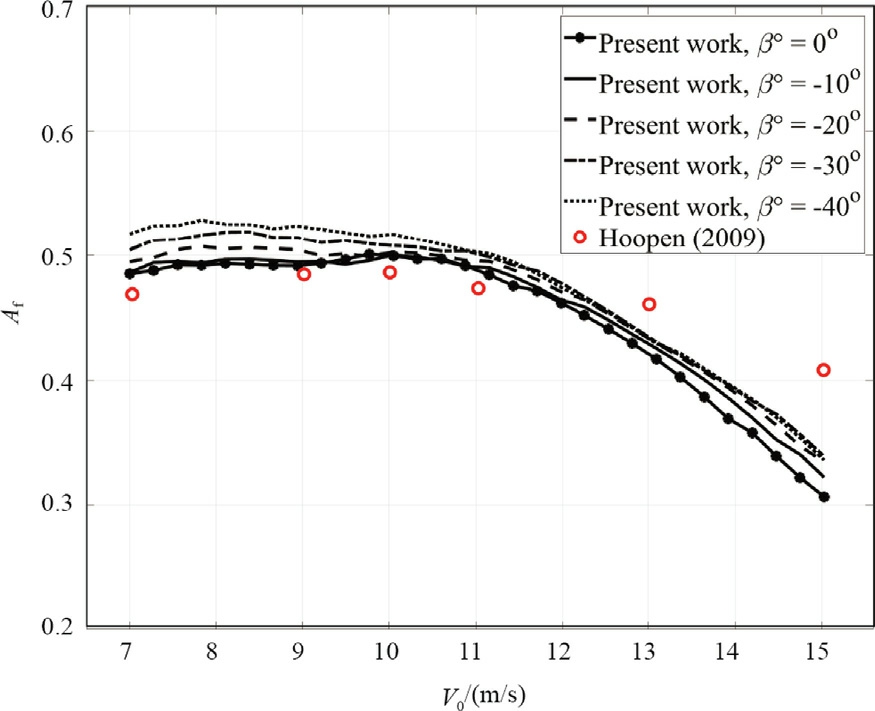
Fig. 10. Augmentation factor for forward sweep effect.
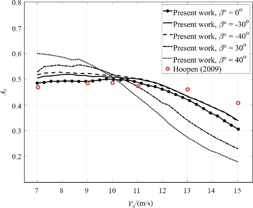
Fig. 11. Augmentation factor for backward sweep effect.
Fig.11 shows the results for the DAWT optimized with backward sweep effect,with the performance analysis conducted at wind speeds between 7 and 11 m/s. The 10°-curved blade depicted an average efficiency increase of 1.07% compared to the straight blade and reached a maximum Afof 0.508 at a wind speed of 9.89 m/s.For the 20°-curved blade, the average increase is Af= 3.45%, and its maximum Afis 0.526 at a wind speed of 9.31 m/s. The 30°-curved blade showed an average increase of Af = 7.05% and a maximum Afof 0.555 at a wind speed of 8.73 m/s. The 40°-curved blade showed an average increase of 8.87% and achieved a maximum Afof 0.60 at a wind speed of 7 m/s. There is a local increase in DAWT efficiency with the backward sweep effect compared to the straight blade. Again,the 30°and 40°angles exhibited the highest performance, but only for wind speeds between 7 and 10 m/s. It is important to note that backward swept blades have a strong decrease in efficiency for high wind speeds. In this case, turbines with forward swept blades seem to keep efficiency higher for a larger range of wind speeds than backward blades.
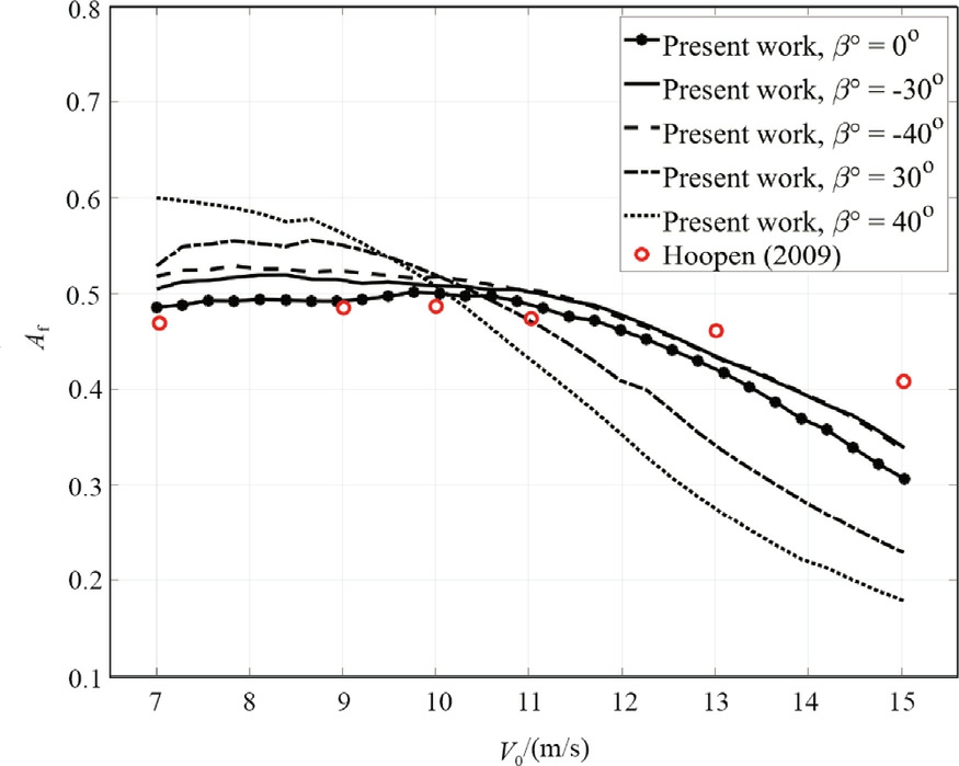
Fig. 12. Comparison between the augmentation factors.
Fig. 12 shows a comparison between both forward swept and backward swept blades. It is noticeable that Afis higher for the blades with backward sweep for the wind speed range 7–10 m/s. The forward swept blades maintained a more stable operation with increasing wind speeds and did not exhibit a sharp decline. A key point to consider is that blades with forward and backward sweep effects in the literature consistently yield distinct results.
The explanation for the difference between these types of curvatures remains underexplored and not well disseminated in the literature. Wærness [25] and Juaristi [26]demonstrate that curved blades exhibit higher efficiency in high turbulence compared to straight blades due to the reduction in vortices, as also shown by Dias and Camacho [13]. However, Wærness [25] and Juaristi [26]do not discuss why blades with forward sweep effect show higher efficiency than blades with backward sweep effect.Based on CFD analyses,it can be assumed that this is also related to the generation and direction of vortices; however, this has not been experimentally confirmed.
It is possible that this behavior is related to the sweep directing the generation and transport of vortices on the blade surface. As suggested by Dias and Camacho [13]and confirmed by experimental and CFD analyses by Wærness [25], Juaristi [26], and Nafi et al. [27], the reduction in vorticity and the reorganization of aerodynamic circulation (Γ) benefit swept blades under more complex flow conditions.Furthermore,the forward sweep may help delay boundary layer separation at higher speeds, which could explain its greater efficiency and operational stability.Studies by Zuo et al.[28],Salari et al.[29],and Pavese et al. [17] also support the hypothesis that different curvatures influence load distribution and aerodynamic efficiency.
From a numerical perspective, for a more accurate analysis using DAWT with sweep effect, it is necessary to add a correction factor or propose a new formulation that considers vorticity phenomena. Blade tip loss factor, on both axial and circumferential flow directions, needs to be further analyzed. Models adjusted based on CFD simulations may incorporate tangential components of vorticity and local blade curvature. The most appropriate turbulence model for analyzing wind turbines with sweep effect is the SST k–ω, which combines the strengths of the k–ω model (strong performance near solid surfaces)and the k–ε model (better accuracy farther from the surface).This model effectively captures boundary layer separation and tip vortices,particularly in regions of curvature and flow redirection, as demonstrated in the CFD studies by Li et al. [16], Zuo et al. [28], and Alipour et al. [30].
In summary, while swept blades demonstrate good effi-ciency in turbulent conditions, the reasons for the performance differences between forward and backward swept blades remain unclear.
2.2 Comparison of the velocity ratio, power, and thrust coefficient for the straight blade
Fig. 13a and b shows the variation of the velocity ratio(ε1)at eachradial position from the center of the diffuser to its inner edge, compared with measurements by Hoopen[1] for the single diffuser configuration (CTd=0.135) and the configuration with 37 vortex generators(CTd=0.1489).Thepresentresults areingood agreement with the previous experimentalwork.Thepresence ofvortex generators helps increase the pressure at the diffuser outlet, consequently enhancing the airflow velocity within the diffuser. Additionally, Nafi et al. [27] investigated the characteristics of the flow near the wake with swept blades,comparing them to a rotor with straight blades.The results show that the wake developed behind the swept blade exhibited relatively less momentum loss and suppressed turbulent activity (mixing and production) compared to the straight blade. Thus, the backward swept blade produced a lift/drag ratio two to three times higher than the straight blade.
Fig.13c and d shows the results of the DAWT with the straight blade for the two configurations adopted in this work. The present analysis allows for the verification of the performance of each configuration. The configuration with 37 VGs showed an average increase of 5.34% in the power coefficient and a 22.34%increase in the thrust coefficient compared to the simple configuration.
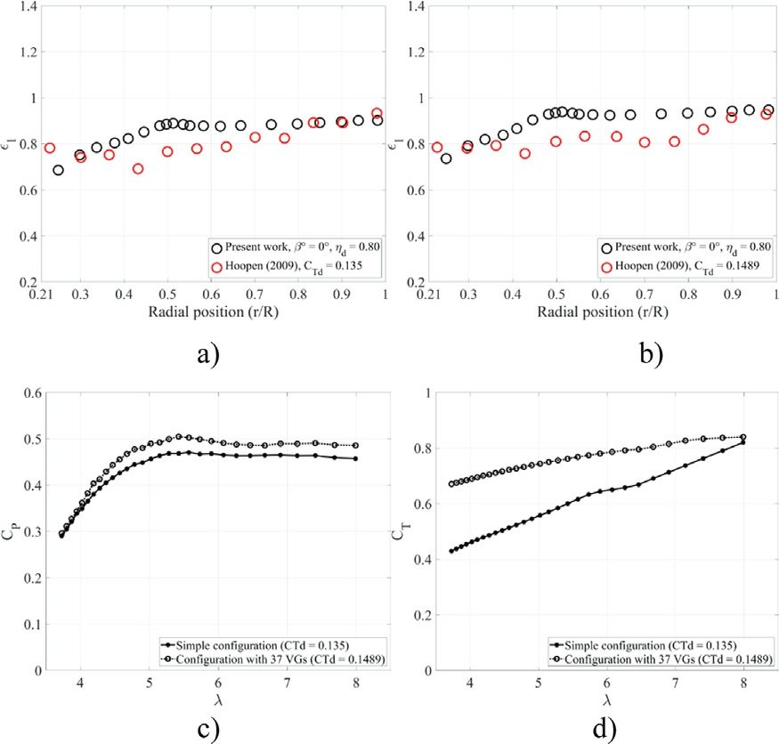
Fig. 13. Rotor with straight blades.
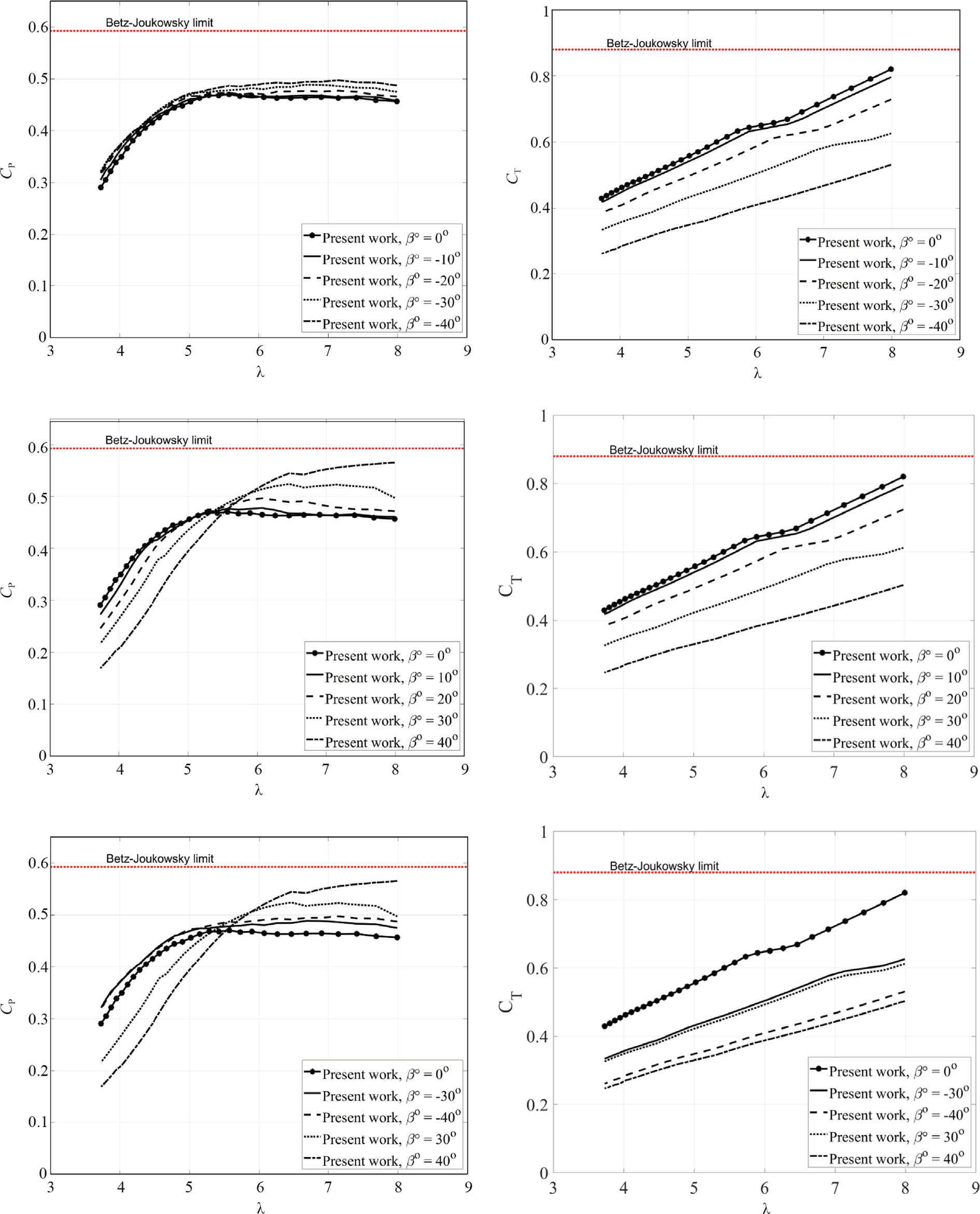
Fig. 14. Performance with simple configuration.
2.3 Power and thrust coefficient for the simple configuration
The results in Fig. 14 show that the power coefficients increase for all tip speed ratios (λ) with forward sweep effect compared to the straight blade rotor. For the backward sweep effect, the increase in the power coefficient only occurs under the following operating conditions: λ from 5.14 to 7.98 (10°); λ from 5.14 to 7.98 (20°); λ from 5.42 to 7.98 (30°); λ from 5.57 to 7.98 (40°). Another important result of the proposed model is that the thrust coefficient decreases as the sweep effect on the blades varies, keeping the thrust coefficient below the Betz-Joukowsky limit. The on the DAWT with curved blades is lower compared to straight blades in both cases,indicating a decrease in the axial aerodynamic load on the rotor with the sweep effect under the analyzed operating conditions.
These results are consistent with the CFD findings of Zuo et al. [28], which suggest that the thrust on curved blades is likely to be lower than on straight blades, with this difference becoming increasingly noticeable as wind speed increases.
Salari et al. [29] found that the rear sweep decreased axial thrust,indicating that the power increase stems from the reduction in drag losses at moderate and high wind speeds. These results reinforce the idea that, although the curved blades have a lower CT,the overall efficiency of the turbine is improved by the reduction in drag and increase in torque, especially at high tip speed ratios. It is important to emphasize that the sweep effect significantly influences circulation(Γ)due to the chord variation,as described in Eq. (8).Although the intensification of the circulation on the blade increases the torque,this does not necessarily reflect in the increase of the thrust coefficient since the curvature of the blade makes the flow less susceptible to boundary layer separation.
2.4 Power and thrust coefficient for the configuration with 37 VGs
AsignificantimprovementinCPfor therotor optimized wit hsweepeffectisshownin Fig.15. Depending onthe operating condition of the DAWT,utilizing curved blades provides greater efficiency compared to straight blades,highlighting the importance of the present optimization.The Betz-Joukowsky limit for the power coefficient is exceeded for the blade with a backward sweep effect of 40°for a λ from 6.9 to 7.9, thereby increasing the output power. At high wind speeds, the CPis close to that of the rotor with the straight blade for the forward sweep effect results but still shows an increase. The rotor with the backward sweep effect exhibits a lower CPcompared to the straight blade at high wind speeds.
Confirming the results of Zuo et al.[28]and Salari et al.[29], the thrust coefficients for both blades with the backward sweep effect are lower.
Additionally, according to Veloso et al. [31], when the wind turbine starts operating,the results indicate that swept blades do not always increase the torque coefficient or reduce the thrust,as indicated in some scientific articles.It depends on the characteristics of the airfoil used for the blades.
2.5 Experimental and proposed model
The present model employs a diffuser configuration with 37 vortex generators, and is compared to the experi-
CT mental results of the diffuser featuring a Gurney flap.Table 2 presents the results from Hoopen [1] and the present work. The difference between the experimental result and the current work with the straight blade is 0.3%,demonstrating good agreement. The diffuser alone can increase the efficiency of a wind turbine, and Hoopen [1]demonstrated possible optimizations in the diffuser that can further enhance the efficiency of the DAWT. Based on the results in Table 2, this work demonstrates that the sweep effect also improves the performance of a DAWT.
Adding different sweep angles, both in forward and backward directions,resulted in variations in the analyzed performance parameters. Specifically, for the forward sweep cases (β°=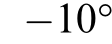 to
to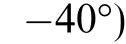 , there is a trend of increasing generated power, reaching a maximum value of 541.60 W at β°=
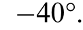 A progressive reduction in the thrust coefficient is observed, decreasing from 0.77 to 0.63 across the forward sweep variation, indicating a reduction in the total force on the system, possibly due to the redistribution of flow around the blades and the lower resistance imposed on the stream. These findings are consistent with the results reported by Zuo et al. [28]and Salari et al. [29].For the backward sweep cases(β°=10–40°),the power output depicted a more significant increase up to β°=30°,followed by a decrease at β°= 40°, where the value dropped to 520.37 W. Due to Af and CPbeing maximized only between 7 and 9.75 m/s for the 40°backward sweep effect, lower power, torque, and thrust coefficients are expected compared to the others.
Additionally, it is observed that backward sweep configurations greater than 30°show a reduction in performance parameters, making them less effective compared to the other configurations tested. This finding suggests the existence of an optimal limit for the sweep effect applied to wind turbine blades.
The comparison with experimental data demonstrates that the proposed model is reliable and suitable for representing the behavior of wind turbines with diffusers and varying blade geometries. Moreover, the results indicate that the sweep effect can be a promising strategy for optimizing the performance of DAWTs, whether the operational and aerodynamic limits are respected.
2.6 Asymmetric comparison between DAWTs
Parallel to the experimental comparison in the present work, the studies done by Dogru and Yilmaz [32] and Hansen et al. [33]are selected to assess the maximum performance of both DAWTs with straight blades.The results presented below for a DAWT are obtained using the equations: and
and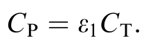 However, the results for the bare wind turbine are obtained using the following classical definitions:
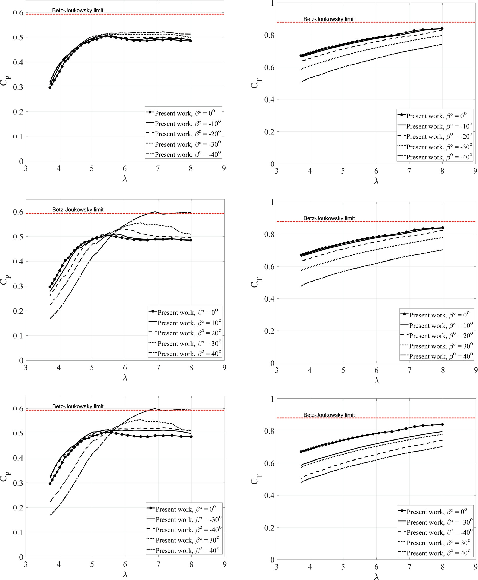
Fig. 15. Performance with 37 VGs configuration.
Dogru and Yilmaz [32] employed a CFD model based on the generalized actuator disk theory to analyze a DAWT, where the sectional diffuser profile is GOE431 with ηd= 0.92 and area ratio of 1.68. Also, Hansen et al. [33] used a CFD approach based on actuator disk theory to analyze a turbine with and without a diffuser.The sectional diffuser profile is NACA0015 with ηd= 0.83 and an area ratio of 0.54. In the present work(Fig. 16), for CTd = 1.12 and ηd= 0.83, the following values are obtained: CPopt =0.941 and CTopt=0.788.For thebare wind turbine, the following values are obtained:CPopt = 0.592 and CTopt= 0.885.
Table 2 Comparison between the proposed model and experimental data(V 0= 10 m/s).
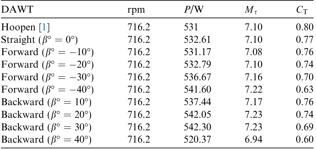
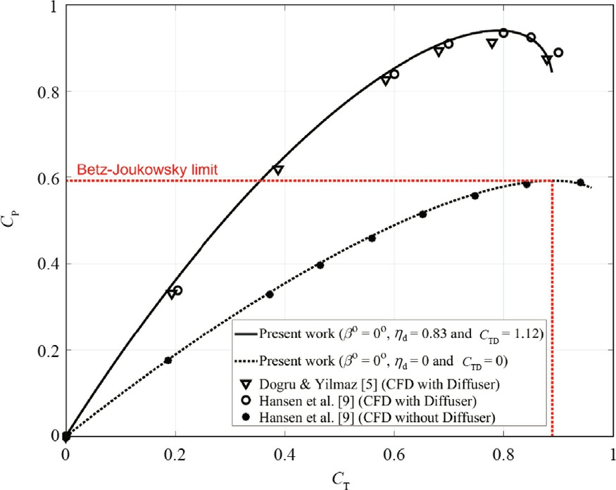
Fig. 16. Optimal power and thrust coefficients.
Table 3 Optimal results achieved for turbines with and without a diffuser.
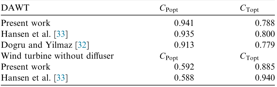
The comparative results of the maximum performance from this work and the literature can be seen in Table 3.The difference between the results of the DAWT from Dogru and Yilmaz [32] and the present work is 2.98%for the optimal power coefficient and 1.14% for the optimal thrust coefficient. For the DAWT from Hansen et al. [33] and the present work, the differences are 0.64%for the optimal power coefficient and 1.50% for the optimal thrust coefficient.For the bare wind turbine,the differences are 0.68% for the optimal power coefficient and 5.85% for the optimal thrust coefficient.
No values for CTdare reported by Dogru and Yilmaz[32] and Hansen et al. [33]. Considering the high values obtained for CPopt, elevated values for CTdare also expected, as CP is directly proportional to CTd.Thus, an optimal CTdsignificantly higher than the experimental values of Hoopen[1]is found.The results show that the maximum performance of the DAWT is achieved only if CTd = 1.12 and ηd= 0.83.
3 Conclusions
The present work demonstrates that curved blades can increase the efficiency of a DAWT, with the best results achieved for curvature angles of 30°and 40°,although this difference is more pronounced between backward and forward swept blades. Additionally, the diffuser provides a considerable gain in power coefficient, validating the use of diffusers as a mechanism to increase the power of wind turbines, especially for small and medium ones. The increase in power of a DAWT is related to the diffuser area,efficiency,and thrust coefficient.As shown in the present work, it also depends on the rotor. Thus, the correlation between these parameters needs to be assessed considering the detailed characteristics of the flow through the diffuser and rotor. The development of this work shows that the power and thrust coefficients are significantly dependent on the diffuser efficiency.
The results obtained from the extended theoretical models show a physical behavior consistent with the experimental data from Hoopen [1], demonstrating their viability for project analysis. Another important point is that optimizations in wind turbines are crucial for achieving higher efficiency, reducing excessive costs associated with satisfactory energy generation,and facilitating installation.The present work demonstrates an innovative approach,as it employs the diffuser, a highly effective performance enhancement method that has been studied for decades,and the sweep effect, which is a current and less explored optimization technique. The use of diffusers and rotor optimization is justified as a viable technology, mainly for small wind turbines.
It is important to highlight some limitations of the present work, such as the formulation for the diffuser thrust coefficient (CTd). Additionally, the end loss factor of the blade for wind turbines with diffusers requires further improvement. The presence of the diffuser significantly alters the flow around the rotor, intensifying recirculation effects and acceleration in the wake region. These changes impact the distribution of induction factors along the blade, particularly near the tip, where the interaction between vortices and the diffuser is more accentuated.With the introduction of the sweep effect in the rotors,the interaction between vortices and the diffuser structures becomes even more relevant in DAWT configurations,requiring more accurate modeling to properly capture the flow behavior. Therefore, it is essential to develop a formulation for the blade tip loss factor that considers both axial and tangential flow. A potential variable in a possible new formulation is the flow turbulence, which influences vortex generation and the performance of wind turbines with sweep effect, as observed by Wærness [25]and Juaristi [26].
The backward sweep configurations exhibited higher augmentation factors at wind speeds of 7–10 m/s, while the forward swept blades maintained more stable operation over a wider range of wind speeds.Regions with moderate winds may benefit more from backward swept blades. In contrast, in areas with greater variability or higher wind intensities, forward swept blades may offer enhanced operational stability and reduced thrust loads.Furthermore, the study confirms the critical importance of diffuser characteristics, particularly its efficiency and thrust coefficient,in influencing turbine performance.This highlights the need for an integrated design approach, in which the geometries of both rotor and diffuser are optimized together.
The augmentation factor results highlight the importance of considering pressure gradients and diffuserinduced wake effects to maximize power generation. As demonstrated in the present work, there are several ways to optimize DAWTs through diffusers, including vortex generators, Gurney flaps, and other possible modifications.
The significant reduction in thrust coefficient observed in the curved blades further suggests an opportunity to decrease structural loads on the system, enabling the use of lighter and more cost-effective supports.This has direct implications for the technical and economic feasibility of DAWTs,especially in small-to medium-scale applications where cost-benefit considerations are critical.
The proposed BEMT model also stands out by providing a rapid and straight forward analysis compared to CFD simulations, which, although more robust, require significant computational resources and processing time.In contrast, the algorithm developed in this work enables reliable results and is very fast, representing a significant reduction in project time. This feature is particularly advantageous for applications in remote areas, as in the Amazon, where limited infrastructure imposes practical constraints on the use of advanced computational tools.Furthermore, the model can be adapted for the study of hydrokinetic turbines in riverine environments, such as streams and small rivers, further expanding its practical applicability.
CRediT authorship contribution statement
Jean C.A. Nobre: Conceptualization, Investigation,Data curation, Formal analysis, Methodology, Writing –original draft. Silvia C.P. Andrade: Resources, Writing –review & editing. David L.P. Sousa: Resources, Writing –review&editing.Tamara Guimaraẽs:Supervision,Validation. Silvio B. Vale: Supervision, Validation. Jerson R.P.Vaz: Conceptualization, Investigation, Data curation,Formal analysis, Methodology, Writing – original draft.
Declaration of competing interest
We declare that we have no conflict of personal or financial interests.
Acknowledgments
The authors would like to thank the Coordination for the Improvement of Higher Education Personnel(CAPES) of Brazil and the Brazilian National Council for Scientific and Technological Development (CNPq)for the provision of master’s scholarships. Also, the authors are grateful to the ANP for their support through PRH program (60/UFPA - 2025/02635-0).
References
[1]P. Hoopen, An Experimental and Computational Investigation of a Diffuser Augmented Wind Turbine: With an Application of Vortex Generators on the Diffuser Trailing Edge. M.sc. thesis.Faculty of Aerospace Engineering,Delft University of Technology.Mekelweg 5, Delft - NL, 2009.
[2]J.R. Vaz, D.H. Wood, Aerodynamic optimization of the blades of diffuser-augmented wind turbines, Energ. Conver. Manage. 123(2016) 35–45, https://doi.org/10.1016/j.enconman.2016.06.015.
[3]C. Fletcher, Computational analysis of diffuser-augmented wind turbines, Energ. Conver. Manage. 21 (1981) 175–183, https://doi.org/10.1016/0196-8904(81)90012-1.
[4]H. Glauert, Aerodynamic Theory, Springer, New York, USA,1935.
[5]G. Batchelor, An Introduction to Fluid Dynamics, C.U.P., 1967.
[6]M.L.A. Gemaque, J.R.P. Vaz, O.R. Saavedra, Optimization of hydrokinetic swept blades, Sustainability 14 (21) (2022) 13968,https://doi.org/10.3390/su142113968.
[7]S.C.D.P. Andrade, D.A. do Rio Vaz, J.R.P. Vaz, A simplified optimization model for hydrokinetic blades with diffuser and swept rotor, Sustainability 16 (2024) 33, https://doi.org/10.3390/su16010033.
[8]P.A.S.F.Silva,L.D.Shinomiya,T.F.de Oliveira,J.R.P.Vaz,A.L.A. Mesquita, A.C.P.B. Junior, Design of hydrokinetic turbine blades considering cavitation, Energy Procedia 75 (2015) 277–282,https://doi.org/10.1016/j.egypro.2015.07.343.
[9]T.M. Pereira, J.R.P. Vaz, A new approach to predict the cascade effect in turbine flowmeters applied to liquefied petroleum gas,Fuentes, El Revento´n Energético 22 (2024) 79–97, https://doi.org/10.18273/revfue.v22n1-2024006.
[10]D.L.P. Sousa, J.C.A. Nobre, J.R.P. Vaz, S.B. Vale, I.H. John, T.M. Pereira, Efecto cascada en una turbina eo´lica de eje horizontal multipala, Fuentes, el Revento´n Energético 22 (2024) 83–91,https://doi.org/10.18273/revfue.v22n2-2024006.
[11]D.L. Barbosa, J.R. Vaz, S.W. Figueiredo, M.D.O.E. Silva, E.F.Lins,A.L.Mesquita,An investigation of a mathematical model for the internal velocity profile of conical diffusers applied to DAWTS,An. Acad. Bras. Cieˆnc. 2 (2015) 1133–1148, https://doi.org/10.1590/0001-3765201520140114.
[12]L.D.S.Borges,J.C.D.A.Nobre,D.L.P.D.Sousa,L.C.F.Andrade,A probabilistic model for flood forecasting based on hydrological data in the state of Maranha˜o, Brazil, Meteorol. Hydrol. Water Manag. 12 (1) (2024) 50–64, https://doi.org/10.26491/mhwm/190951.
[13]M.M.G.Dias, R.R. Camacho,Optimization of nrel phase vi wind turbine by introducing blade sweep, using cfd integrated with genetic algorithms, J. Braz. Soc. Mech. Sci. Eng. 44 (2022) 19,https://doi.org/10.1007/s40430-021-03357-y.
[14]M.G.Khalafallah,A.M.Ahmed,M.K.Emam,The effect of using winglets to enhance the performance of swept blades of a horizontal axis wind turbine, Adv. Mech. Eng. 11 (9) (2019),https://doi.org/10.1177/1687814019878312.
[15]J.C.A. Nobre, D.L.P. Sousa, J.R.P. Vaz, S.B. Vale, Análisis de desempen˜o de aerogeneradores con difusor y pala curva, Fuentes,el Revento´n Energético 22(2024)99–106,https://doi.org/10.18273/revfue.v22n1-2024007.
[16]A. Li, G.R. Pirrung, M. Gaunaa, H.A. Madsen, S.G. Horcas, A computationally efficient engineering aerodynamic model for swept wind turbine blades, Wind Energy Sci. 7 (2022) 129–160, https://doi.org/10.5194/wes-7-129-2022.
[17]C. Pavese, T. Kim, J.P. Murcia, Design of a wind turbine swept blade through extensive load analysis, Renew. Energy 102 (2017)21–34, https://doi.org/10.1016/j.renene.2016.10.039.
[18]D. Wood, V. Okulov, Nonlinear blade element-momentum analysis of betz-goldstein rotors, Renew. Energy 107 (2017) 542–549, https://doi.org/10.1016/j.renene.2017.02.027.
[19]J.R. Vaz, D.H. Wood, Effect of the diffuser efficiency on wind turbine performance, Renew. Energy 126 (2018) 969–977, https://doi.org/10.1016/j.renene.2018.04.013.
[20]D. Wood,V. Okulov,J. Vaz, Calculation of the induced velocities in lifting line analyses of propellers and turbines, Ocean Eng. 235(2021), https://doi.org/10.1016/j.oceaneng.2021.109337 109337.
[21]R. Alipour, R. Alipour, F. Fardian, M.H. Tahan, Optimum performance of a horizontal axis tidal current turbine:a numerical parametric study and experimental validation, Energ. Conver.Manage. 258 (2022), https://doi.org/10.1016/j.enconman.2022.115533 115533.
[22]R. Alipour, R. Alipour, S.S. Rahimian Koloor, M. Petru˚, S.A.Ghazanfari,On the performance of small-scale horizontal axis tidal current turbines. Part 1: one single turbine, Sustainability 12 (15)(2020) 5985, https://doi.org/10.3390/su12155985.
[23]R.Alipour,R.Alipour,R.Fardian,S.S.Koloor,R.Moezzi,Effect of blade pitch angle on a 2-bladed horizontal axis tidal current turbine performance, in: Proceedings of the 62nd International Conference of Machine Design Departments (ICMD 2022),Atlantis Press, 2024, pp. 2589–4943, https://doi.org/10.2991/978-94-6463-423-5_22.
[24]R. Alipour, R. Alipour, M. Rezaeimanesh, M.H. Tahan, M.Dehghan, Heat transfer enhancement in a tubular heat exchanger fitted with a novel baffle: a numerical study and experimental validation,Int.J.Therm.Sci.215(2025),https://doi.org/10.1016/j.ijthermalsci.2025.109936 109936.
[25]T. Waerness, An Experimental Study of the Effects of Turbulence on the Performance of a Wind Turbine Model With Forward and Backward Swept Blades. Master’s thesis. Faculty of Engineering,Norwegian University of Science and Technology, 2021.
[26]L. Juaristi. An experimental study of the performance of a wind turbine model with swept blades, for different inflow conditions.Master’s thesis. Faculty of Engineering, Norwegian University of Science and Technology, 2023.
[27]A.S. Nafi, K. Krishnan, A.K. Debnath, E.E. Hackett, R. Gurka,Wake characteristics of a freely rotating bioinspired swept rotor blade, R. Soc. Open Sci. 8 (2021) 1–13, https://doi.org/10.1098/rsos.210779.
[28]H. Zuo, C. Liu, H. Yang,F. Wang, Numerical study on the effect of swept blade on the aerodynamic performance of wind turbine at high tip speed ratio, J. Phys. 753 (2016), https://doi.org/10.1088/1742-6596/753/10/102010 102010.
[29]M.S. Salari, B.Z. Boushehri, M. Boroushaki, Aerodynamic analysis of backward swept in hawt rotor blades using cfd, Int. J.Renew. Energy Dev. 7 (2018) 241–249, https://doi.org/10.14710/ijred.7.3.241-249.
[30]R. Alipour, R. Alipour, R. Fardian, S.S. Koloor, M. Petru˚,Performance improvement of a new proposed Savonius hydrokinetic turbine: a numerical investigation, Energy Rep. V 6(2020) 3051–3066, https://doi.org/10.1016/j.egyr.2020.10.072.
[31]M.J.G. Veloso, C.H.P. Santos, J.R.P. Vaz, A.M.C. Neto, Quasisteady analysis of a small wind rotor with swept, Sustainability 15(2023) 10211, https://doi.org/10.3390/su151310211.
[32]S. Dogru, O. Yilmaz, Extensive design and aerodynamic performance investigation of diffuser augmented wind turbine(DAWT) guided by generalized actuator disc theory, Renew.Sustain. Energy Rev. 192 (2024), https://doi.org/10.1016/j.rser.2023.114212 114212.
[33]M. Hansen, N. Sørensen, R. Flay, Effect of placing a diffuser around a wind turbine,Wind Energy 3(2000)207–213,https://doi.org/10.1002/we.37.
Received 14 April 2025;revised 2 October 2025; accepted 13 October 2025
Peer review under the responsibility of Global Energy Interconnection Group Co. Ltd.
* Corresponding author.
E-mail address: jean.nobre@ananindeua.ufpa.br (J.C.A. Nobre).
https://doi.org/10.1016/j.gloei.2025.10.002
2096-5117/°2025 Global Energy Interconnection Group Co. Ltd. Publishing services by Elsevier B.V. on behalf of KeAi Communications Co. Ltd.This is an open access article under the CC BY-NC-ND license(http://creativecommons.org/licenses/by-nc-nd/4.0/).

Jean Nobre Holds a Bachelor’s degree in Science and Technology with an emphasis in Mechanics and a Master’s degree in Mechanical Engineering, both from the Federal University of Pará. Experienced in Renewable Energy,Structural Thermal Performance, and Thermal Comfort.