0 Introduction
Distribution networks are the last link to meet the need for electrical energy in power systems. Under normal condition and due to the relatively high power factor of residential consumers, the distribution network and feeders have to provide both active power (in watts) and reactive power (in VArs) to residential consumers. However, for other types of consumers, especially for industrial ones,the required reactive power component is often very significant. This generally reduces the power factor to less than 0.9 at the connection point to the network or say as common coupling point[1].The increase in the reactive power component in the distribution feeders leads to several technical and economic issues such as higher active power losses, greater voltage drop across the feeder, and line amperage capacity reduction due to reactive power component[2].To reduce the technical and economic problems caused by reactive power flow in feeders, electricity distribution companies and network operators define allowable power factor ranges for different types of consumers, particularly industrial ones. Then, if a consumer exceeds the allowable limit, power factor monetary penalty and reactive power costs are imposed. The allowable power factor limit for industrial loads is usually announced as 0.9 [3],which is generally violated due to the nature of the loads in industrial centers. Various strategies have been implemented to compensate the reactive power and improve the power factor at different points of the industrial plants networks as well as improve the voltage profile and reduce the power losses.These strategies involve using flexible static and dynamic power transmission equipment, installing static reactive power compensators, utilizing static and adjustable capacitors, by synchronous motors/machines/-condenser [4–6] and etc. Some of the initial attempts have taken into account the application of capacitor banks as the most reliable, at-hand, easy-to-installation, and costeffective approach in reactive power compensation of distribution networks [7–12]. These studies demonstrate the main functionality of capacitor banks in voltage profile improvement, power losses reduction, and reactive power provision. In this way, the necessity of capacitor banks adoptions in distribution networks, microgrids (MGs),and industrial complexes is highlighted.
In recent years,studies on use of the parallel capacitors in power systems, especially in distribution networks and industrial MGs, have attracted the attention of many researchers. These capacitors are used for different purposes. In [13–16], parallel capacitors are used to reduce power losses and improve voltage profile in distribution networks. The optimal placement of capacitor in an MG is studied in [17]. The objective function of the presented model minimizes power system losses in both gridconnected and islanded modes. To solve the power flow equations, this model employs the Gauss-Seidel method.The authors of[18]solve the problem of optimal capacitor placement in sub-transmission substations.To improve the power factor of the substations, they have used a geneticfuzzy algorithm. Moreover, these authors determine the optimal placement and sizing of parallel capacitors based on sensitivity analysis.In this way,the load reactive power is met and the power factor at the network connection point increases to about unity. However, the overall performance of the network is not enhanced in this approach.The authors of [16] present a model for voltage profile optimization and power loss minimization using parallel capacitors based on the flower pollination algorithm.This algorithm is used to determine both the location and sizing of parallel capacitors in distribution networks. Considering the load growth in distribution networks, the optimal placement and sizing planning model for capacitors in distribution networks in a multi-year horizon is studied and proposed in [19]. The objective function of the proposed model involve power loss minimization and voltage profile improvement.
In[20–23],the focus is on improving voltage characteristics by optimal placement and sizing of capacitors. In[20],the location of voltage regulators and their tap changing ratio are specified to simultaneously minimize the total system losses and keep the voltage within a reasonable range.In[23],the effects of bus voltage and feeder current constraints on the performance of the presented model are investigated. Here, the corresponding multi-objective problem is solved using a modified particle swarm optimization technique. In [24], the objective function is formulated as a function of power losses cost, investment costs, and operating costs of capacitor banks. This problem and the reconfiguration scheme are addressed using a specialized genetic algorithm. In [25,26], reliability indices are improved through optimal placement and sizing of capacitors. Coelho et al. have proposed a model for evaluating the reliability indices in the presence of shunt capacitor banks by considering voltage drop and feeder loading constraints. This model evaluates postrestoration voltages without modifying the data structure used for reliability evaluation [26]. In primary studies on optimal capacitor placement, most of the developed models have been established based on analytical approaches.With the development of novel computational techniques and the emergence of powerful computer processors,numerical methods were proposed to choose the optimal placement and sizing of capacitors, taking into account all operating constraints. Furthermore, innovative methods with minimized computational burden and search space were proposed to solve the problem of optimal placement and sizing of capacitors [15]. In recent years,several methods based on artificial intelligence and metaheuristic algorithms have been developed to solve this problem [25–29]. Although capacitor placement has had a long trace in distribution systems, still is an interesting and applicable issue to be dig all around the world [30–36]. As well, modern approaches of reactive power compensation are also surveyed in distribution networks demonstrating its importance in power system studies[37–40].
The present study aims at optimal reactive power compensation as well as optimal placement and sizing of parallel capacitors in an industrial MG involving petrochemical industry loads.Urmia Petrochemical industrial MG is a part of Urmia distribution network with certain geographical boundaries [17]. Additionally, MGs are operated mainly under the authority and supervision of a single entity and managed in a unified manner. An industrial MG operator should use some strategies and equipment to compensate reactive power to avoid economic losses because of penalty coefficients for excessive reactive power consumption as well as to prevent technical problems such as power losses in distribution feeders and voltage drops across loads.Placing fixed capacitor is one of the most economical and accessible solutions for reactive power compensation. The variables that must be determined in the optimal capacitor placement problem are the optimal location for installing capacitors and optimal size of capacitors.Another issue that should be considered is the implementability of the problem of optimal capacitor placement in industrial MGs using their actual infield characteristics. In the present study, four different scenarios are introduced and their effects on voltage quality improvement and network power losses reduction are investigated. The first approach focuses on centralized compensation of reactive power at the main distribution substation of this MG. The second approach considers group compensation of reactive loads fed from a common bus in a distributed manner. The third approach focuses on the simultaneous use of shunt capacitors at the main substation and at the buses collecting the loads of each industrial plant. In the fourth approach, the problem of optimal capacitor placement is solved simultaneously for the main buses feeding the feeders of each industrial plant,the main substation, and along the medium voltage main feeder. Although the reactive power compensation problem in traditional distribution networks has been widely investigated and comprehended such as the literatures reviewed here,this problem has been given a less attention in isolated small networks such as MGs with their realistic constraints. Hence, although the mathematical backbone of the developed models would resemble, their management strategies and real-world conditions and constraints within the distribution networks and those of the MGs’would not be the same. In this way, this study is one of the first ones reporting such a research with these conditions to be archived. These networks are not the same as the standard test networks and would face with their own specific characteristics; hence, comparing the proposed models would not face with similar conditions.The proposed model takes into account the real constraints of the reactive power compensation such as space limitations in bulk capacitor placement in pre-installed electrical panels of industrial plants, diversity of loads,coincident considering of the middle-line or along-line compensation through the primary feeder of the MG beside its in-field grouped compensation, coincidence of reactive power compensation, voltage improvement, and power factor enhancement. The main highlights of this study are:
An insightful reactive power compensation in real MGs by spatio-temporal constraints;
Maintaining problem optimality considering the objectives and constraints;
Benchmarking centralized and distributed reactive power compensation for industrial MGs;
Simultaneous voltage quality improvement, power losses minimization,and power factor correction during capacitor placement.
The remainder of this paper is organized as follows. In Section 2, the mathematical model of the optimal placement and sizing of capacitor banks is presented and the objective function and optimization problem constraints are introduced, too. In Section 3, a real-world industrial MG say as Urmia Petrochemical plant is introduced and explored in different strategies of reactive power compensation.The results of applying the proposed model to this MG in different scenarios are discussed. At the end, the concluding remarks are presented in Section 4.
1 Mathematical modeling
In this section, the mathematical model of load flow and the problem of optimal placement and sizing of capacitor banks are presented. The presented model has nonlinear terms; accordingly, non-linear solvers are called to solve it.
1.1 Objective function
Improving voltage profile and power factor are two main objectives.Accordingly,the objective function in this study can be defined as follows:

where w1 and w2 are the weighting coefficients being equally set at 0.5 and FVDI and FPF are the functions for voltage quality improvement by minimizing the summation of buses voltage deviations from unity and power factor improvement of the network by minimizing reactive power absorption from the external network. The following equations are considered:

where i is the MG’s buses index,B is the set of buses,V i is the voltage magnitude of bus i,Qsub and Psub are the active and reactive powers imported from the upstream network.
1.2 Load flow and operating constraints
Active and reactive power balances at buses are among the main equations of load flow, given by (4)–(7).
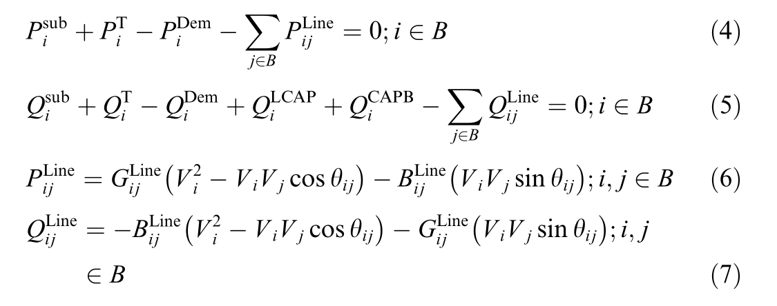
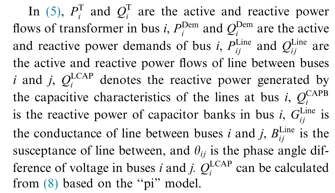

where, ω is the angular velocity and is the capacitance due to capacitive effect of line between buses i and j.
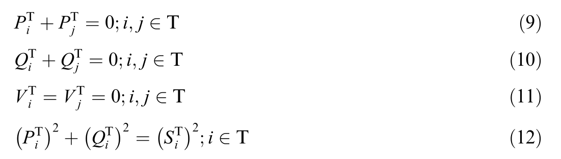
Transformers are common equipment of power networks and can be modeled using (9)–(12). It should be noted that in the following model, transformers losses are neglected and the taps are set to 1.
Besides, power networks have some operational constraints that must always be met in order to guarantee the quality of the power provided to the consumer and network security issues.
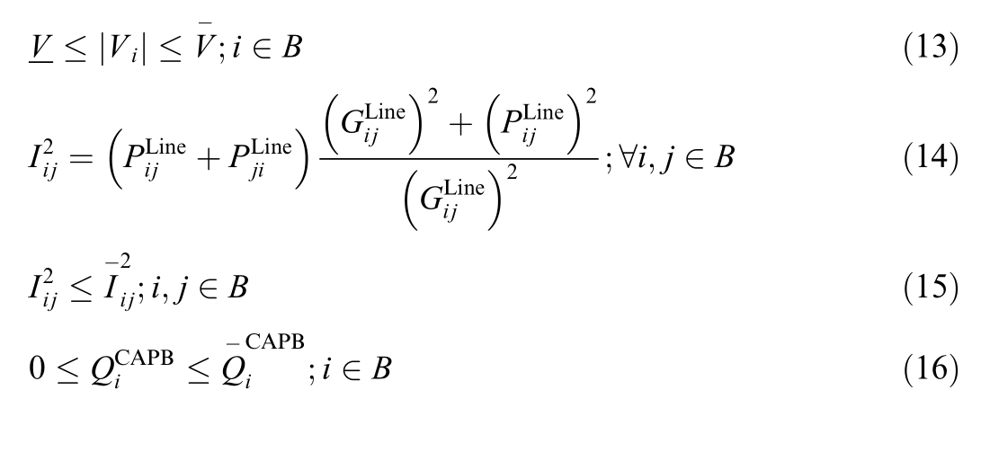
where Iij is the current through the line between buses i and j. In the present study, it is assumed that, according to the nature of the network, the active power flow is always from the upstream substation to the consumer;so, (17) is considered.

The‘‘spatio”constraints relate to the constraints in conjunction with the space limits in installing new capacitors.As mentioned in the revised manuscript,the electrical panels of the industrial plants could host limited capacity of capacitors which is due to space limitations.This constraint is modeled by the maximum amount of capacitor which could be placed along with the existing capacitors inside each electrical panel. Also, ‘‘temporal” constraints relate to the daily and varying currents and power loadings of all loads inside the network which are carefully included in the developed model by active and reactive powers balances, maximum current limitation of feeders, and voltage quality preserve at each time interval of operational scheduling.The flowchart of the developed model is shown in Fig. 1.
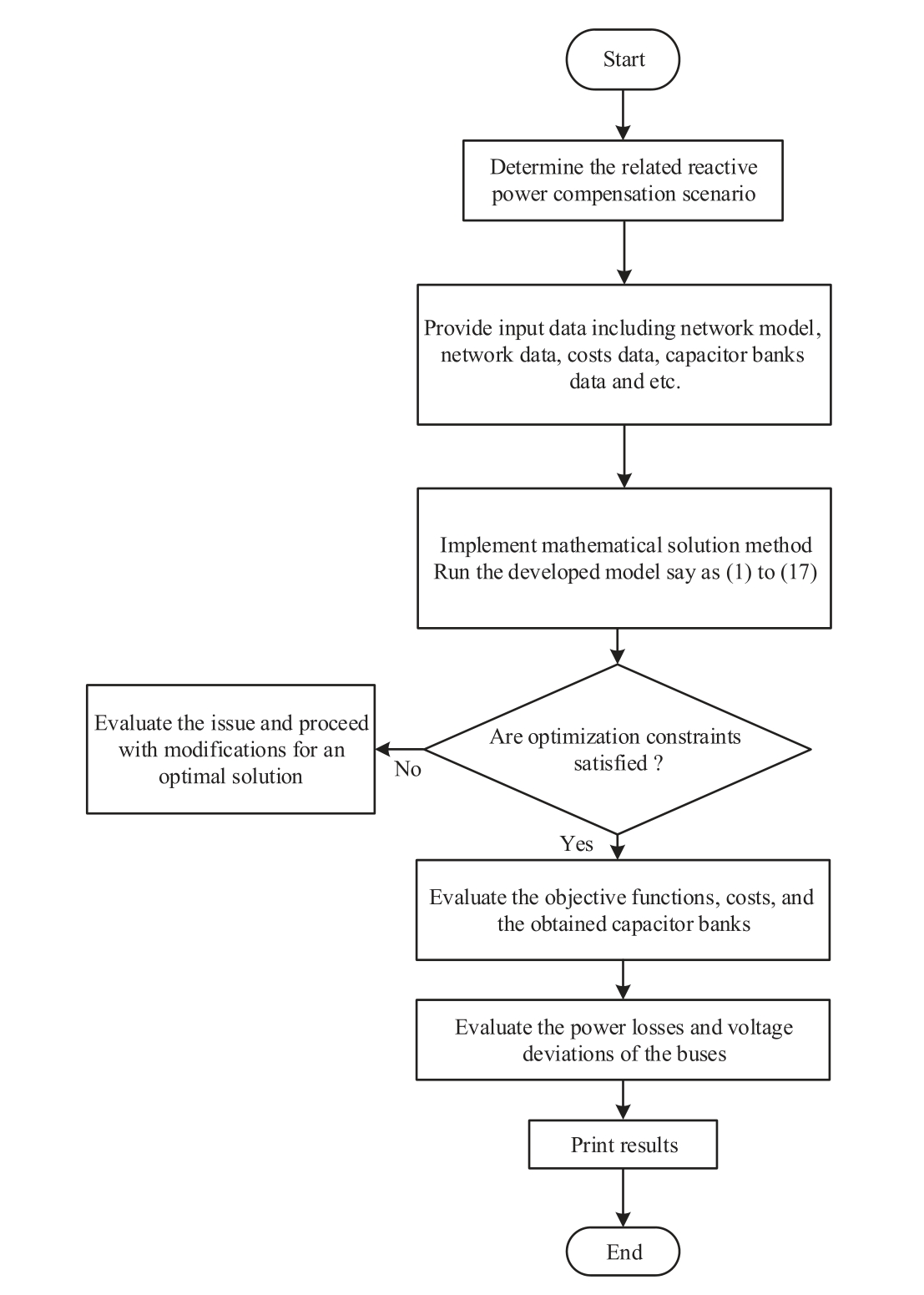
Fig. 1. Flowchart of the developed model.
2 Numerical investigations
In this study,Urmia Petrochemical MG is tailored considering the aforementioned distributed reactive power compensation strategies. This MG is directly connected to Urmia 20 kV medium voltage distribution network.The schematic of this network is shown in Fig. 2.
As shown in Fig.2,Urmia Petrochemical plant’s network has eight different sub-plants with the load specifications presented in Table 1.These specifications include the number of loads,power factor,maximum capacity,and current operating capacity of each plant.Note that the data represented in Tables 1–3 is the real system data of this MG.
In expanding the Urmia Petrochemical MG, its future expansions have been also considered. For instance, in 10 to 15 years, this MG might face with load growth and reach to its maximum designed ratings, referred to as maximum load capacity in tables and simulated figures.Plant C is currently not in operation and its load is zero.There is a previously connected existing capacitor bank in each plant with the specifications given in Table 2.
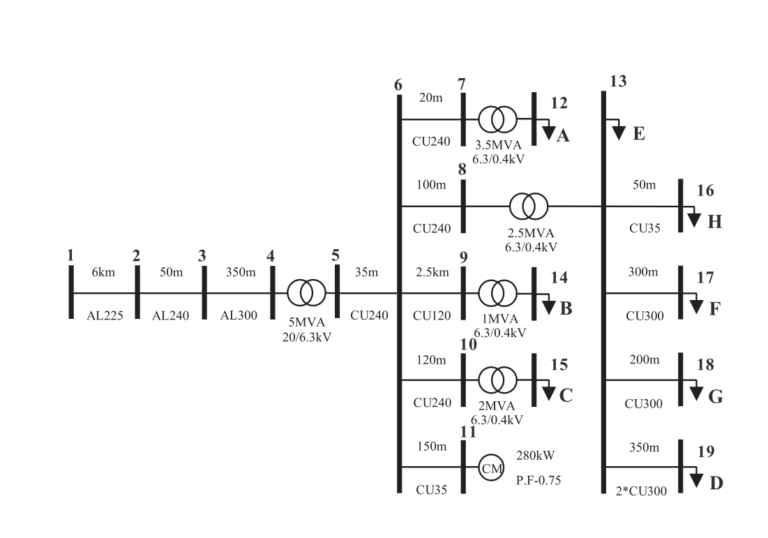
Fig. 2. Single-line diagram of Urmia Petrochemical MG.
Table 1 Test network loads.
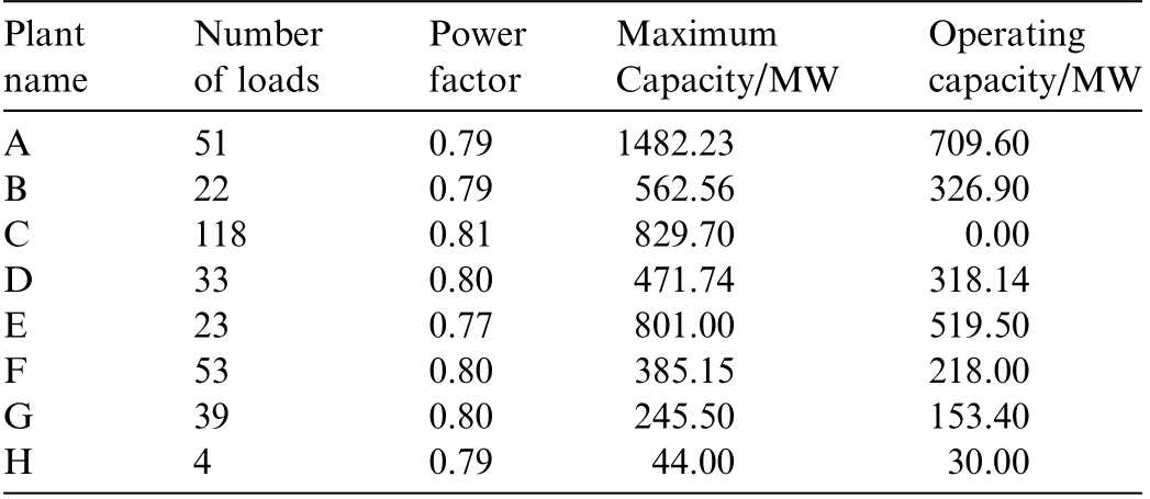
Table 2 Capacitor banks in the network.

The main objective is to site and size capacitor banks and allocate them to minimize voltage deviation and power losses as well as to maximize power factor.For this purpose, by providing the input data say as the network,the load, and also the capacitors specifications, the results are obtained based on the developed optimization model being solved by General Algebraic Modeling System(GAMS) software which is a high-level optimization platform developed for implementing and solving linear, nonlinear,and mixed-integer optimization problems and could be used in real-world and industrial optimizations. The problem is tailored in five different scenarios and the results are presented in the following subsections.
2.1 Scenario 1: Without reactive power compensation due to absence of capacitor banks
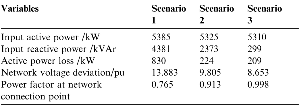
In this scenario,the network is operated without capacitor banks. Accordingly, there is not any reactive power compensation and the reactive power is totally supplied through the distribution network. Here, due to high reactive power flow along the feeders, voltage deviation and large amount of losses are expected.By providing the basic data such as network model and topology,load,and other related information, the power flow model, stated within(1)–(17), is executed. The voltage profiles of different plants in this scenario are shown in Fig. 3. As expected,the voltage range of most plants is unacceptable by exceeding the permissible lower and upper limits say as 0.95 p.u.and 1.05 p.u, respectively. The network voltage deviation and other details of the network are presented in Table 3 for further investigation.As can be seen,besides high voltage deviation,low power factor and high power losses are other observations in this scenario. As a result, this scenario is not suitable for network operation.
Table 3 Overall network status in scenario 1.
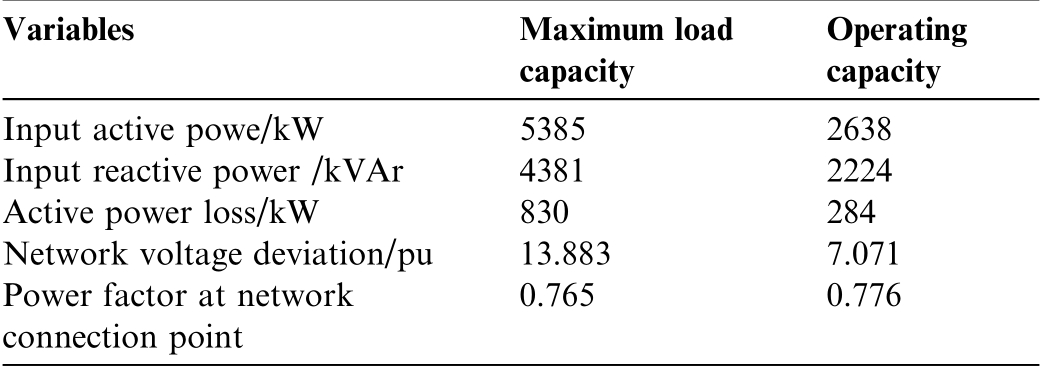
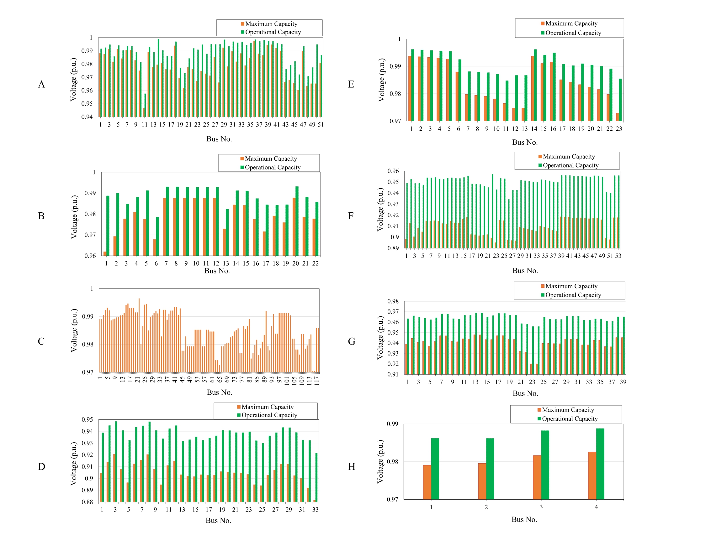
Fig. 3. Voltage profile of plants in scenario 1.
2.2 Scenario 2: Distributed group compensation by only existing capacitor banks
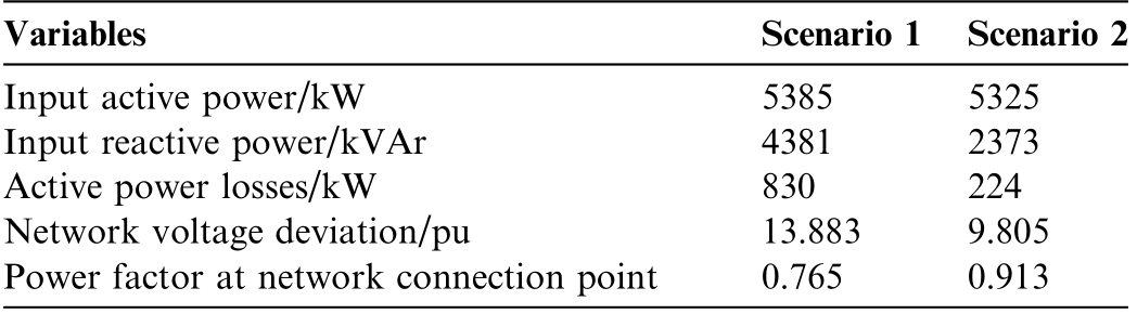
In this scenario, the existing capacitor banks in electrical panels of buses,given in Table 2,are considered in the network. Such as case refers to supposing the electrical loads of each bus as a group and hence due to several buses inclusion in the process, distributed group compensation is realized. Seven capacitor banks with a total capacity of 1945 kVAr are included in this scenario.Table 4 shows the state of capacitor banks in scenario 2.According to this table, although some capacitor banks are present in some plants, they are not deployed. The details of the network status are shown in Table 5.According to this table, despite a high voltage deviation in scenario 2, a significant improvement is achieved compared to scenario 1. However, careful measurement of activepower losses and power factor of the network in this scenario signifies a need to change and improve the status of the existing capacitor banks.
Table 4 Existing capacitor size (kVAr) for maximum load capacity in scenario 2.
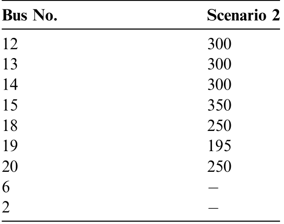
Table 5 General network operation status for maximum load capacity in scenario 2.
2.3 Scenario 3: Distributed group compensation by possibility of upgrading existing capacitor banks
Considering distributed group compensation strategy,it is assumed that the pre-installed existing capacitor banks in the electrical panels of buses can be upgraded. Table 6 shows the obtained results. Here, seven capacitor banks with a total capacity of 4005 kVAr are installed. It is seen that the size of the capacitor banks of almost all plants has increased compared to previous case. The details of the network status are shown in Table 7. As can be seen, the network performance indicators in this scenario are well improved compared to the previous scenarios. However,it is aligned with some concerns. First, since the location of the capacitor bank is limited to the location of the existing banks, the size of the capacitor bank would be very large; so, it may be impossible to install a capacitor bank with this size due to space limitation.Second,if a capacitor bank fails, the other banks cannot supply the reactivepower required by the plant,and the operation of the plant may be seriously hampered.
Table 6 Capacitor size (kVAr) for maximum load capacity in scenario 3.
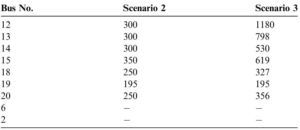
Table 7 General network operation status for maximum load capacity in scenario 3.
2.4 Scenario 4: Distributed group compensation by upgradeable existing capacitor banks and centralized compensation in main substation bus
In this scenario, besides the possibility to upgrade the existing capacitor banks in electrical panels of buses as the distributed group compensation, a centralized capacitor bank can be installed at bus 6 as a common connection point of the plants. Additionally, the maximum allowed capacity for installing capacitor banks is considered 750 kVAr. The results of this scenario are shown in Table 8.In this scenario,eight capacitor banks with a total capacity of 4255 kVAr are installed.As can be seen,in this scenario, the capacity of all capacitor banks is less than 750 kVAr, and bus 6 has 728 kVAr of reactive power acting as a backup reactive power supply to improve the performance indicators. Details of the network status are shown in Table 9. These details indicate that most of the performance indicators in scenario 4 are similar to those in scenario 3; hence, the improvement is not significant.However, in this scenario, the size of upgraded capacitor banks in previously existing capacitor banks is smaller;so, this scenario outperforms scenario 3 because it leads to higher network reliability. A more careful look at the results in Table 9 reveals that in scenario 4, despite the presence of several capacitor banks, 50 kVAr reactive power is still received from the transmission network which could be locally provided. This can be attributed to the reactive power losses of the network feeders and the primary long feeder.
2.5 Scenario 5: Distributed group compensation by upgradeable existing capacitor banks, centralized compensation in main substation bus, and distributed shunt capacitor alongside the main primary feeder
This scenario is the most comprehensive state of the previous scenarios. Here, the existing capacitor banks can be upgraded up to the maximum capacity of 750 kVAr andnew capacitor banks can be installed at buses 2 and 6.Table 10 shows the results of this scenario in which nine capacitor banks with a total capacity of 4304 kVAr are considered. Therefore, by installing a capacitor bank at bus 2,the capacity of the capacitor bank at bus 6 is reduced.Moreover,the capacitor banks installed at buses 2 and 6 have to jointly provide the reactive power required by the feeders as well as to increase the network reliability.The details of the network status are presented in Table 11. Accordingly, in this scenario, since reactive power is supplied locally within the network,the reactive power drawn from the distribution network reaches zero; hence, the power factor at the network connection point is equal to unity.
Table 8 Capacitor size (kVAr) for maximum load capacity in scenario 4.
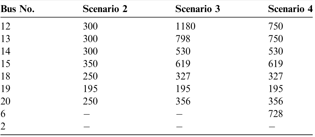
Table 9 General network operation status for maximum load capacity in scenario 4.

Table 10 Capacitor size (kVAr) for maximum load capacity in different scenarios.
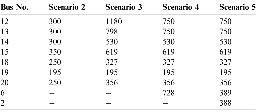
Fig.4 shows the voltage profiles of the plants in this scenario. A careful look at the voltage profile of the plants shows that the load voltage in this scenario is much better than that of the scenario 1.
3 Conclusion
In this study,capacitor placement with different configurations in the power system of an industrial real-world MG was investigated. For this purpose, at first, the network was operated without any capacitor banks. In this scenario (scenario 1), due to the high power flow in the network, the load voltage was very low, active power losses were high, and network power factor was not acceptable. In scenario 2, the capacitor banks existing in the network were connected, and with their optimal adjustment,the overall network status was improved compared to the first scenario.Moreover,it was observed that in the case of maximum load capacity, the existing capacitor banks could not supply the reactive power of the network,and a significant amount of required reactive power was drawn from the distribution network. As a result,despite the significant improvement in scenario 2,the need for further improvement was clearly evident.In scenario 3,it was possible to upgrade the capacity of the existing capacitor banks.In this way,the main part of the reactive power required by the load was provided by the capacitors, and as a result, the network performance indicators improved, compared to scenario 2. This scenario was found to have drawbacks such as the large size of capacitor banks and the low reliability of the proposed structure.In scenario 4, the common connection point of the plants was considered as the new installation location for the backup capacitor bank.Accordingly, by limiting the maximum capacity of capacitor banks to 750 kVAr,it was suggested to install a capacitor bank with a capacity of 728 kVAr at bus 6. Although the drawbacks of scenario3 were resolved by installing the new capacitor, due to reactive power losses in the primary long feeder of the network, part of the reactive power required by the network was still supplied by the upstream network, and this was the main disadvantage of the structure in scenario 4. In scenario 5, as the evolved version of the previous scenarios, in addition to the capacitor banks in scenario 4,another capacitor bank was considered at the sending end of the long feeder line. Finally, the numerical results showed that in this scenario, the reactive power drawn from the transmission network reached zero, and the power factor was unity. Furthermore, in scenario 5, the best possible voltage profile was obtained for the plants.In this way, 74.81% improvement in power losses reduction, 1.3% lower active power import from the main grid,23.5% improvement in power factor, and 37.5% improvement in network voltage deviation summation were seen compared to the base case.
Table 11 General network operation status for maximum load capacity in different scenarios.

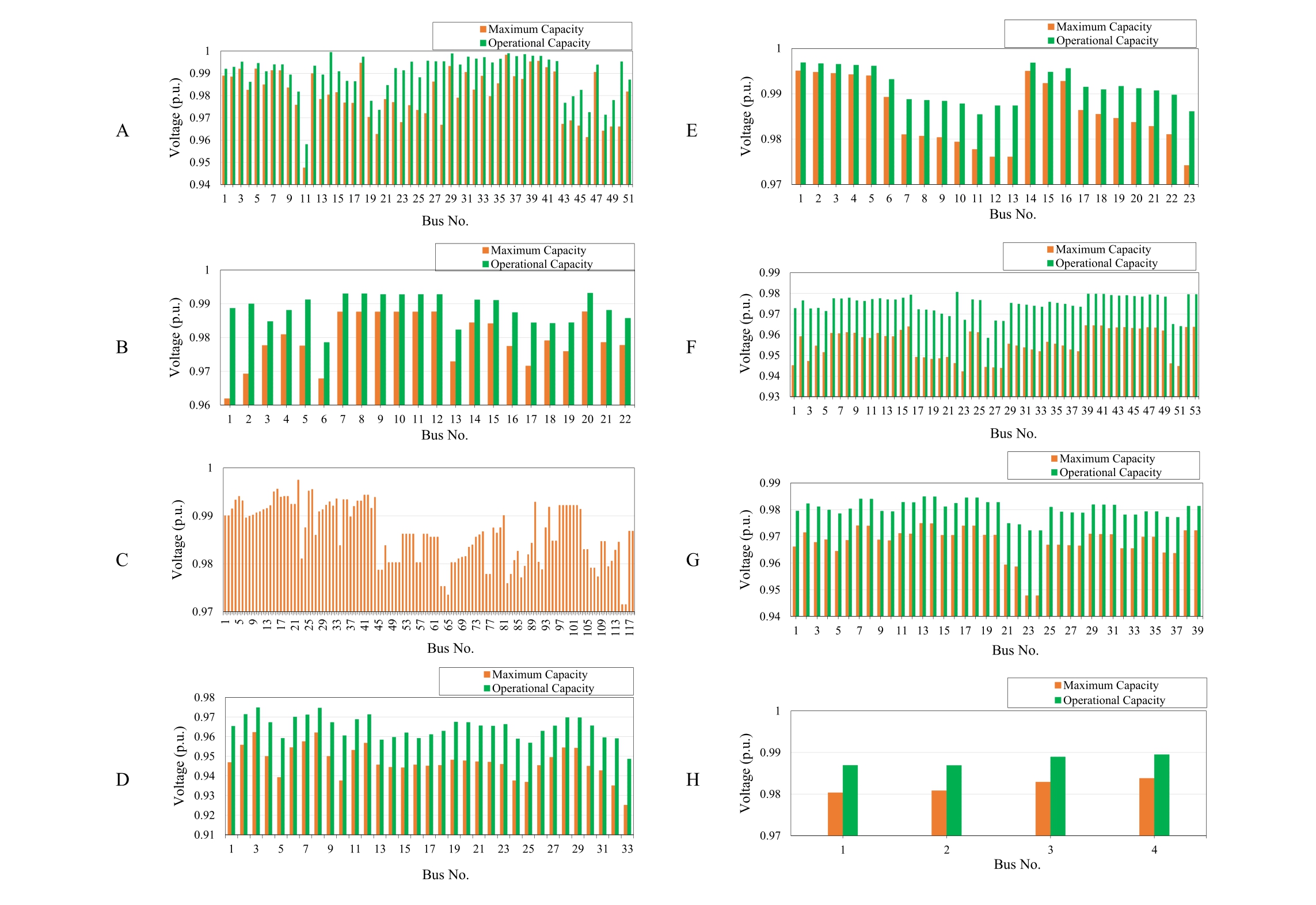
Fig. 4. Voltage profile of the plants in scenario 5.
Besides the investigated issues, considering the load operating specifications, modeling the non-linearity of loads, group and individual compensations of large loads over long distances would be of research interests to be pursued within the ongoing studies.Considering the initial results obtained, adjoining annular investment cost and benefit analysis of capacitor placement, modern reactive power resources inclusion such as embedded soft-starters inverters and photovoltaics or active filters’ inverters still could be further investigated in this paradigm.
CRediT authorship contribution statement
Maryam Majidzadeh: Writing – review & editing, Validation,Project administration,Formal analysis,Writing–original draft, Software, Methodology, Data curation,Visualization, Resources, Investigation, Conceptualization. Mostafa Esmaeeli: Writing – review & editing, Validation, Project administration, Formal analysis, Writing– original draft, Software, Methodology, Data curation,Visualization, Resources, Investigation, Conceptualization. Hadi Afkar: Writing – review & editing, Validation,Resources, Writing – original draft, Supervision, Project administration, Formal analysis, Visualization, Software,Methodology, Data curation, Investigation, Conceptualization. Sajjad Golshannavaz: Writing – original draft,Supervision, Project administration, Formal analysis,Visualization, Software, Methodology, Data curation,Writing–review&editing,Validation,Resources,Investigation, Conceptualization. Zhiyi Li: Visualization, Software, Methodology, Data curation, Writing – review &editing, Validation, Resources, Investigation, Conceptualization, Writing – original draft, Supervision, Project administration, Formal analysis.
Declaration of competing interest
We declare that we have no conflict of interest.
Acknowledgments
There is not specific acknowledgments.
References
[1]P.Asabere,F.Sekyere,P.Ayambire,et al.,Optimal capacitor bank placement and sizing using particle swarm optimization for power loss minimization in distribution network, J. Eng. Res. 13 (2)(2025) 1307–1315.
[2]M.T.L. Gayatri, A.M. Parimi, A.V. Pavan Kumar, A review of reactive power compensation techniques in microgrids, Renew.Sustain. Energy Rev. 81 (2018) 1030–1036.
[3]IEEE recommended practice for powering and grounding electronic equipment (2006). IEEE Std 1100-2005 (Revision of IEEE Std 1100-1999): 1-703.
[4]A.A´guila Te´llez,G.Lo´pez,I.Isaac,et al.,Optimal reactive power compensation in electrical distribution systems with distributed resources, Review. Heliyon 4 (8) (2018) e00746.
[5]H. DIrIk, C. GezegIn, H.S. DIrIk, Reactive power compensation with hybrid compensator combining a synchronous motor and switched capacitors, Electr. Pow. Syst. Res. 216 (2023) 109010.
[6]N.Kumar,O. Buwa,A review on reactive power compensation of distributed energy system,in:Proceedings of 2020 7th International Conference on Smart Structures and Systems (ICSSS). 2020 in Chennai, 2020, pp. 1–6.
[7]J.J. Grainger, S.H. Lee, Optimum size and location of shunt capacitors for reduction of losses on distribution feeders, IEEE Trans. Power Syst. 100 (3) (1981) 1105–1118.
[8]M. Kaplan, Optimization of number, location, size, control type,and control setting of shunt capacitors on radial distribution feeders, IEEE Trans. Power Syst. 103 (9) (1984) 2659–2665.
[9]A.A.El-kib,J.J.Grainger,K.N.Clinard,et al.,Placement of fixed and/or non-simultaneously switched capacitors on unbalanced three-phase feeders involving laterals,IEEE Trans.Power Syst.104(11) (1985) 3298–3305.
[10]S.Civanlar,J.J.Grainger,Volt/var control on distribution systems with lateral branches using shunt capacitors and voltage regulators part III: the numerical results, IEEE Trans. Power Syst. 104 (11)(1985) 3291–3297.
[11]A.M. Sharaf, S.T. Ibrahim, Optimal capacitor placement in distribution networks, Electr. Pow. Syst. Res. 37 (3) (1996) 181–187.
[12]C. Alvarez, R. Molina, Distribution networks loss reduction:Capacitor allocation and operation,IFAC Proceedings Volumes 25(1) (1992) 287–292.
[13]E.S.Jones, N.Jewell, Y. Liao, et al., Optimal capacitor placement and rating for large-scale utility power distribution systems employing load-tap-changing transformer control, IEEE Access 11 (2023) 19324–19338.
[14]B.A. Kumar, M. Rani, Sweta, Optimal sizing and placement of capacitor on radial distribution system using genetic algorithm.Materials Today: Proceedings, 2023, https://doi.org/10.1016/j.matpr.2023.03.347.
[15]M.M. Aman, G.B. Jasmon, A.H.A. Bakar, et al., Optimum shunt capacitor placement in distribution system: a review and comparative study, Renew. Sustain. Energy Rev. 30 (2014) 429–439.
[16]V. Tamilselvan, T. Jayabarathi, T. Raghunathan, et al., Optimal capacitor placement in radial distribution systems using flower pollination algorithm, Alex. Eng. J. 57 (4) (2018) 2775–2786.
[17]H.E.Z. Farag, E.F. El-Saadany, Optimum shunt capacitor placement in multimicrogrid systems with consideration of islanded mode of operation, IEEE Trans. Sustain. Energy 6 (4)(2015) 1435–1446.
[18]S.R.Gampa,D.Das,Optimum placement of shunt capacitors in a radial distribution system for substation power factor improvement using fuzzy GA method, Int. J. Electr. Power Energy Syst. 77(2016) 314–326.
[19]O. Sadeghian, A. Oshnoei, M. Kheradmandi, et al., Optimal placement of multi-period-based switched capacitor in radial distribution systems, Comput. Electr. Eng. 82 (2020) 106549.
[20]A.Y. Abdelaziz, S.F. Mekhamer, M.H. Nada, A fuzzy expert system for loss reduction and voltage control in radial distribution systems, Electr. Pow. Syst. Res. 80 (8) (2010) 893–897.
[21]N.A. Masood, A. Jawad, K.T. Ahmed, et al., Optimal capacitor placement in northern region of Bangladesh transmission network for voltage profile improvement, Energy Rep. 9 (2023) 1896–1909.
[22]S.Thongsuk,A.Ngaopitakkul,W.Kotesakha,et al.,An approach for voltage drop improvement in 22 kV PEA distribution system based on high voltage capacitor placement, Energy Rep. 9 (2023)48–54.
[23]I. Ziari, G. Ledwich, A. Ghosh, et al., Optimal allocation and sizing of capacitors to minimize the transmission line loss and to improve the voltage profile, Comput. Math. Appl. 60 (4) (2010)1003–1013.
[24]M.A.N.Guimara˜es,C.A.Castro,R.Romero,Distribution systems operation optimisation through reconfiguration and capacitor allocation by a dedicated genetic algorithm, IET Generat., Trans.Distribut. 4 (11) (2010) 1213–1222.
[25]F. Salinas-Herrera, D. Jayaweera, M.S. Alvarez-Alvarado, et al.Reliability study of a smart distribution system with optimal sizing and placement of capacitors. In: Proceedings of 2021 IEEE PES Innovative Smart Grid Technologies - Asia (ISGT Asia), 2021 in Brisbane, Australia, 2021. Pp. 1-6.
[26]A. Coelho, C.L.C. de Castro, M.G. Da Silva, et al., Inclusion of voltage drop and feeder loading constraints in the evaluation of reliability indices for radial distribution networks,IEE Proceedings- Generation, Transmission and Distribution 153 (6) (2006) 661.
[27]K.E.Adetunji,I.W.Hofsajer,A.M.Abu-Mahfouz,et al.,A review of metaheuristic techniques for optimal integration of electrical units in distribution networks, IEEE Access 9 (2020) 5046–5068.
[28]S.A. Salimon, O.I. Omofuma, O.O. Akinrogunde, et al., Optimal allocation of shunt capacitors in radial distribution networks using Constriction-factor Particle Swarm Optimization and its technoeconomic analysis, Franklin Open 7 (2024) 100093.
[29]M.W. Saddique, S.S. Haroon, S. Amin, et al., Optimal placement and sizing of shunt capacitors in radial distribution system using polar bear optimization algorithm,Arab.J. Sci.Eng.46(2)(2021)873–899.
[30]M. Mahdavi, A. Awaafo, K. Schmitt, et al., Economical installation of capacitor banks in optimal places of distribution feeders considering load fluctuations, IEEE Trans. Ind. Appl. 60(5) (2024) 7646–7655.
[31] M.Mahdavi,A. Awaafo, S.Z.Djokic, et al., An innovative power loss and cost minimization framework for distribution networks with uncertain variable loads by coordinating reconfiguration,capacitor installation and renewable generators placement, IEEE Trans. Ind. Appl. 60 (5) (2024) 7500–7510.
[32]I. Kim, Optimal distributed generation allocation for reactive power control, IET Generat., Trans. Distrib. 11 (6) (2017) 1549–1556.
[33]L.A. Gallego, J.M. Lo´pez-Lezama, O.G. Carmona, A mixedinteger linear programming model for simultaneous optimal reconfiguration and optimal placement of capacitor banks in distribution networks, IEEE Access 10 (2022) 52655–52673.
[34]B. Stojanovic´, T. Rajic´, Distribution network reconfiguration and capacitor switching in the presence of wind generators,Electr.Eng.104 (4) (2022) 2249–2266.
[35]I. Kim, R.G. Harley, Examination of the effect of the reactive power control of photovoltaic systems on electric power grids and the development of a voltage-regulation method that considers feeder impedance sensitivity, Electr. Pow. Syst. Res. 180 (2020)106130.
[36]A. Bosovic, H. Renner, H. Friedl, et al., Optimal placement of power quality monitors by accounting for several key power quality disturbances, Electr. Eng. 106 (3) (2024) 2877–2892.
[37]L. Arubolu, R. Kollu, R.R. Manyala, A multi-objective approach for optimal placement of renewable energy sources, voltage regulators and capacitors in radial unbalanced distribution systems, Electr. Eng. 106 (6) (2024) 6797–6814.
[38]I. Kim, R.G. Harley, The transient-state effect of the reactive power control of photovoltaic systems on a distribution network,Int. J. Electr. Power Energy Syst. 99 (2018) 630–637.
[39]T. Das, R. Roy, K.K. Mandal, Solving the cost minimization problem of optimal reactive power dispatch in a renewable energy integrated distribution system using rock hyraxes swarm optimization, Electr. Eng. 107 (1) (2025) 741–773.
[40]I. Kim, Optimal capacity of storage systems and photovoltaic systems able to control reactive power using the sensitivity analysis method, Energy 150 (2018) 642–652.
Received 15 August 2024;revised 6 February 2025; accepted 11 February 2025
Peer review under the responsibility of Global Energy Interconnection Group Co. Ltd.
E-mail addresses: mmajidzadeh@tvu.ac.ir (M. Majidzadeh), esmaeeli@birjandut.ac.ir (M. Esmaeeli), h-afkar@tvu.ac.ir, h-afkar@nus.ac.ir(H. Afkar), s.golshannavaz@urmia.ac.ir (S. Golshannavaz), zhiyi@zju.edu.cn (Z. Li).
https://doi.org/10.1016/j.gloei.2025.02.005
2096-5117/© 2025 Global Energy Interconnection Group Co. Ltd. Publishing services by Elsevier B.V. on behalf of KeAi Communications Co. Ltd.
This is an open access article under the CC BY-NC-ND license(http://creativecommons.org/licenses/by-nc-nd/4.0/).
Maryam Majidzadeh was born in 1987 in Urmia,Iran.She received her Ph.D.,M.Sc.and B.S. degrees in Electrical Engineering from Urmia University in 2016, 2012, and 2009,respectively. Now she is an assistant professor in Department of Electrical and Computer Engineering, Urmia Girls Faculty, West Azerbaijan branch, Technical and Vocational University (TVU), Urmia, Iran. Her research interests are in electromagnetic compatibility,frequency selective surfaces, MIMO antennas,antenna bandwidth enhancement and antenna miniaturization techniques, circularly polarized antennas, and numerical method in electromagnetics.