
0 Intr oduction
To meet the ‘‘dual carbon” goals and speed up the creation of a new power system focused on renewable energy,quickly increasing wind and solar power generation causes big changes in system frequency. This arises from the inherent uncertainty and intermittency of these renewable sources, thereby posing new challenges to power grid frequency stability [1,2]. Conventional thermal power plants exhibit prolonged response times and gradual ramping rates, rendering them incapable of satisfying the frequency regulation demands of the modern power system. Consequently, novel frequency regulation strategies are required to mitigate the frequency regulation burden on thermal power plants [3,4].
Energy storage, as a superior frequency regulation resource, exhibits rapid reaction and regulation capabilities, effectively mitigating the inadequacy of frequency regulation capacity in conventional thermal power units[5,6].Current energy storage systems are classified into two primary categories: energy-based and power-based. Pumpedstorage hydroelectricity, a conventional energy storage system, provides benefits including cheap operational expenses and substantial regulation capability, establishing it as a principal approach for frequency regulation in power grids. Nonetheless, because to its elevated energy density, diminished power density, and limited cycle life,it is unsuitable for numerous charge–discharge cycles.Conversely, flywheel energy storage, as a conventional power-type energy storage device, has the benefits of low energy density, high power density, and immunity to performance degradation from many charge–discharge cycles.A HESS that integrates pumped-storage hydroelectricity with flywheel energy storage is proposed to aid thermal power plants in primary frequency management, due to the complementing performance attributes of the two systems [7,8].
By coordinating and regulating various energy storage systems, complementary energy storage modes can be attained to enhance the stability and safety of the power system.Reference[9] presents a hybrid energy storage primary frequency control strategy utilizing enhanced inertial response, which significantly improves frequency control efficacy, diminishes the likelihood of frequency overshoot,and bolsters the stability margin of system frequency operation. Reference [10] presents a control strategy for lithium-ion battery-flywheel systems and a regional dynamic PFR model for thermal power units, resulting in a 30.81% decrease in frequency fluctuations, a 43.65%decrease in power fluctuations, and a 23.17% increase in actual power contribution.Reference [11] suggests a twolayer optimization model for using hybrid energy storage to help wind power manage frequency, using fuzzy logic predictive control. This approach mini mizes frequent state transitions in battery energy storage systems, thereby significantly extending their service life.Reference [12] presents a thorough frequency regulation approach that adaptively modifies the droop coefficient and inertia coefficient based on the frequency regula tion stage, thereby attaining synergistic benefits between droop and inertia control strategies. Literature [13] introduces a method for virtual inertia control. Literature [14] assesses the frequency regulation efficacy of flywheel-assisted thermal power units by analyzing the maxi mum frequency variation,peak discrepancy,and standard deviation.Literature[15] suggests a flexible teamwork method for controlling frequency in systems that combine flywheel energy storage with thermal power units. This approach notably reduces both the maximum frequency deviation and steady-state frequency deviation.
While the aforementioned studies confirm the effectiveness of HESSs in PFR, several challenges remain unresolved: 1) The influence of the high-frequency element of PFR commands on thermal power units has been overlooked; 2) The performance of HESSs predominantly relies on droop control and inertia control, lacking the capability to dynamically adjust the droop and inertia coefficients in response to frequency regulation effects and SOC;3) The internal power distribution within HESSs has not been optim ally managed, preventing the full exploitation of energy storage regulation characteristics.
This research offers a hybrid energy storage participation technique for PFR control utilizing NRBO-VMD and FNN to overcome the aforementioned concerns. A PFR model for the pumped-storage-flywheel energy storage system was developed. Secondly, in the initial power allocation phase, a power allocation control approach utilizing NRBO-VMD was devised, taking into account the distinct response characteristics of thermal power plants and energy storage systems, therefore significantly minimizing the ramping losses of thermal power units. An adaptive coordinat ion control technique was presented for the HESS. modifies the inertia coefficient and droop coefficient in accordance with frequency regulation depth and SOC to ensure optimal power distribution inside the HESS. A FNN is utilized for the secondary adjustment of power distribution in the HESS. The proposed control approach is ultimately validated by simulation analysis.
1 Coordinated PFR model of thermal Power-HESS
1.1 Dynamic model of regional power grid frequency regulation
The turbine transfer function is given by

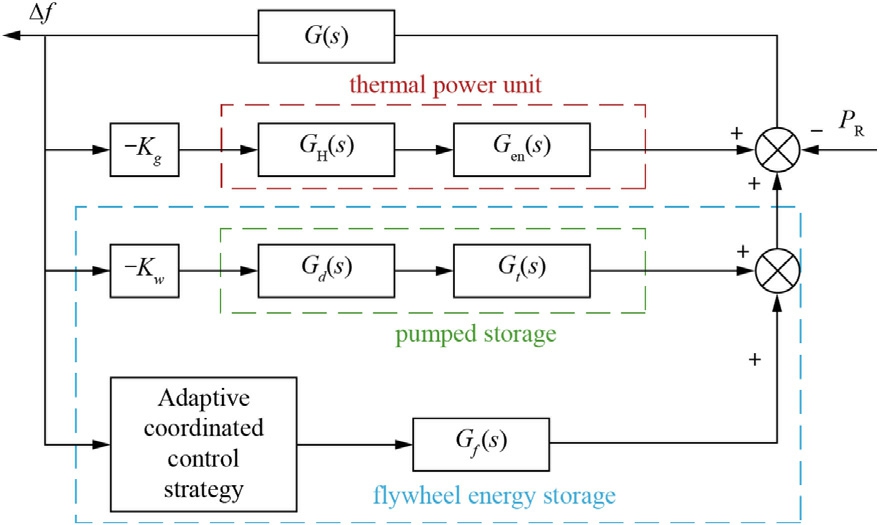
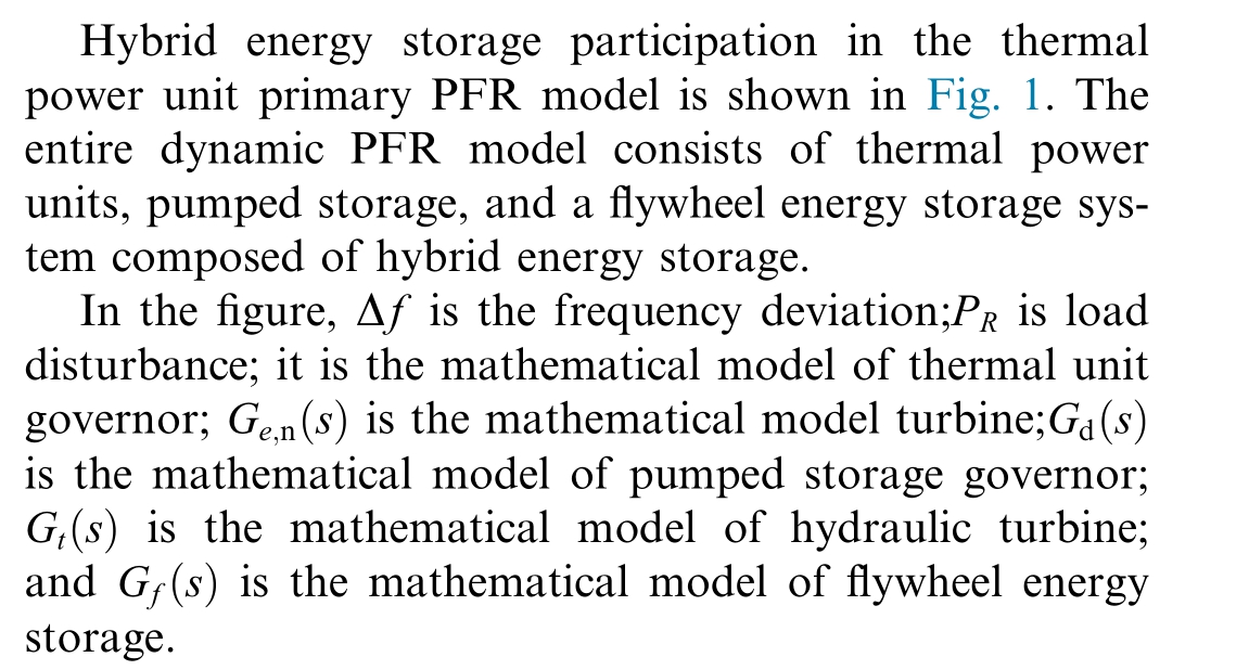
Fig. 1. Hybrid energy storage primary PFR model.
where: TCH and T RHis the turbine time constant, rehe ater time constant; FHPis the reheat er gain.
The transfer function of thermal power unit governor is.

where: TGis the thermal unit governor time constant.
Generator-load model transfer function.where: H is the generator inertia constant; D is the generator load damping factor.

1.2 Energy storage system model
This research primarily examines the basic frequency management approach for thermal power units within HESSs. Consequently, both flywheel arrays and pumped storage systems employ first-o rder inertia models with high precision as equivalent energy storage models to minimize computational requirements [16].
The equivalent model of the flywheel array energy storage system mainly consists of three parts: the flywheel array itself, the SOC detection module, and the PCS.The flywheel array itself is generally modeled using a first-order inertial element, as shown in the equation:

where: TFASSis the inertial time constants for flywheel array energy storage systems.
Based on the definition of the SOC of the flywheel array energy storage syst em the SOC at the moment f can be obtained as.

where: SOC 0 is the initial state of charge; PFAESSis the output power of the flywheel array energy storage system;En is the total capacity of the flywhee l array energy storage system.
The flywheel array energy storage system releases or absorbs energy through the Power Conversion System(PCS) grid, and the actual power output of the flywheel array energy storage system to the grid after PCS is:

where: ηis the energy conversion efficien cy of PCS.
Based on the above analysis, the equivalent model of flywheel array energy storage system can be established as shown in Fig. 2.
This paper exemplifies a standard pumped storage unit.The frequency characteristics of the pumped stora ge unit in power generating mode are mostly associated with the dynamic processes of the turbine and governor. In pumping mode, the pumping power is fixed and does not adjust to variations in system frequency [17].
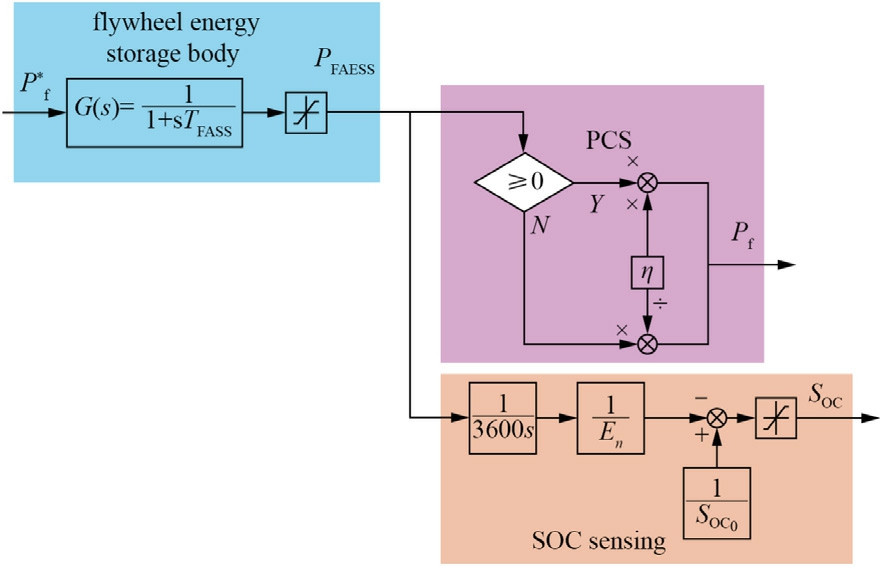
Fig. 2. Flywheel energy storage equivalent model.
Ideally, the hydraulic turbine transfer function can be expressed as follows.

where: Twis the water flow inertia time constant.
Hydraulic turbine governors are chiefly categorized into two types: mechanical and electro-hydraulic. The latter is predominantly utilized in next-generation hydraulic turbine units. This study utilizes the presently accessible electro-hydraulic governor, characterized by the following transfer function:
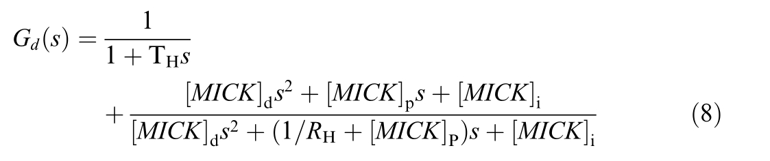
where: Kp, Kd, Ki are the proportional, differential and integral coefficients of the governor; the time constant of the governor of the pumped storage unit;and the differential coefficient of the pumped storage unit.
In summary, the frequency response model for a pumped storage unit operati ng in generation mode can be established.

2 Control strategy for primary power distribution of hybri d energy storage participating in PFR
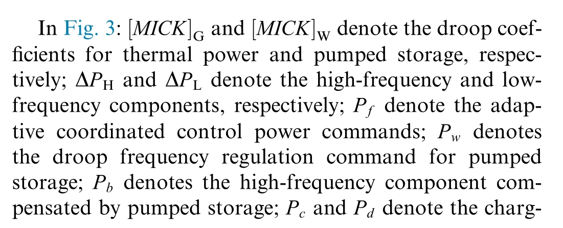
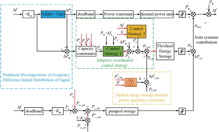
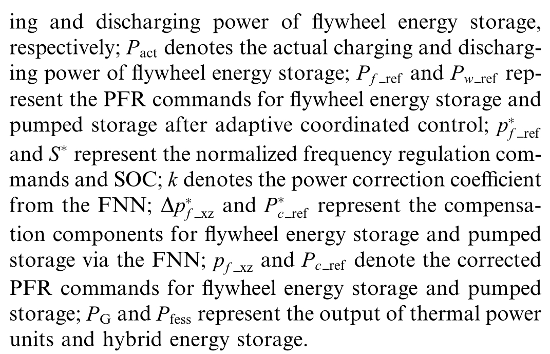
Fig. 3. Block diagram of primary PFR control strategy.
2.1 RNBO-VMD-based signal decomposition
Decomposition typically utilizes techniques including high-pass filtering, wavelet transformation, and shorttime Fourier transformation. Nonetheless, these methods fail to precisely extract the high-, medium-, and lowfrequency modal components of the original signal when analyzing nonlinear mixed energy storage target power signals. This work employs an enhanced VMD method to analyze the target power of the energy storage system according to frequency characteristics, thus mitigating decomp osition imbalances induced by human variables.VMD partitions a signal into K sub-signals by predetermined values of k and the penalty factor. The methodology for executing VMD decomposition on a frequencymodulated command signal is based on the theoretical approaches outlined in References [18,19]. The VMD parameters for noise tolerance and convergence error are configured to their default values of 0.1 and10 6, respectively. NRBO, derived from the method in [20], i s employed to determine the parameter combination (K,α)in the VMD algorithm. This enables the adaptive adjustment of VMD parameters based on the signal ’s features and complexity, hence enhancing decomposition accuracy and outcomes.
VMD analyzes the PFR command signal into many intrinsic modal components. Permutation entropy is a statistic that quantifies the randomness and complexity of a signal sequence, effectively capturing dynamic variations in data. Nevertheless, it alone represents data at a singular scale. This study presents multi-scale permutation entropy (MPE) as an enhanced approach to permutation entropy, thereby more accurately capturing the signal’s complexity,as suggested in Reference[21]. This study uses MPE as the fitness function for NRBO. MPE does this through multi-scale coarse-graining of the time series signal, followed by the computation of permutation entropy values , thus efficiently extracting signal feature information. The specific calculation principle of MPE is introduced in detail in Reference [22]. The MPE values for each intrinsic mode function (IMF) obtained through VMD can be computed systematically. Lower MPE values indicate more orderl y and stable time series, while higher values correspond to increasingly complex and stochastic series.
By carefully calculating the MPE values for the different intrinsic modal functions obtained from VMD decomposition, we can find the MPE values for each intrinsic modal function. A lower entropy value indicates a more stable and orderly time series, while a higher entropy value signifies a more complicated and random time series (Fig. 4).
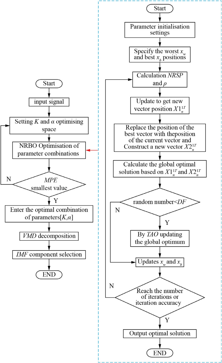
Fig. 4. NRBO-VMD decomposition process.
2.2 NRBO-VMD based power primary allocation
Upon assessing the complexity of each modal component of the frequency control command using MPE, components over the threshold are classified as high-frequency,while those below the threshold are classified as lowfrequency. The energy storage system and the thermal power unit manage them, as demonstrated in the subsequent equation:


The command signal assumed by the energy storage system can be obtained by the following equation.

The command signal assumed by the thermal unit can be obtained by the following equation.

3 Adaptive coordinated control strategy and internal power allocation for hybrid energy storage systems
3.1 Adaptive coordinated control strategy
Control strategies differentially impact PFR: Positive virtual inertia control helps slow down how quickly the frequency changes right after a disturbance, negative VIC helps reduce the frequency change during recovery,and droop control keeps the frequency steady during the whole event.To optimize frequency regulation,these techniques are synergistically integrated, leveraging their complementary dynamics [23,24].
The coordination framework operates on the following principle: Droop control is the main way to manage frequency during the whole process, while positive VIC only kicks in when the frequency is at its lowest point,and negative VIC only works during the recovery phase. Under this coordinated strategy, the output of Control Strategy Module 2 yields

where: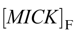 and M Fare the sag and inertia coefficients,respectively.
To enhance the SOC retention rate of the flywheel array energy storage system, this study employs variable coeffi-cient sag control and virtual inertia control. The formulation of the sag coefficient is presented as follows:
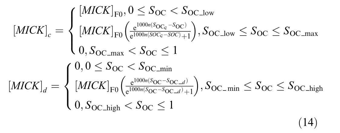
where: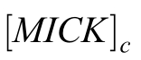 and
and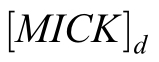 are the inertia coefficients for chargi ng and discharging, respectively.
The expression for the virtual inertia coefficient is:
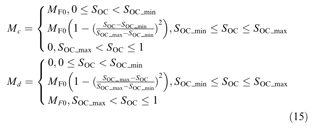
where: Mc an M dare the inertia coefficients during charging and discharging, respectively.
It can be seen from Eqs. (14) and (15) that the conventional variable droop coefficient and variable inertia coefficient are only related to the SOC and cannot be adaptively adjusted according to the frequency regulation depth. To address this issue, this paper proposes a control method that can adaptively adjust the inertia coefficient and droop coefficient based on the frequency regulation depth. This method is mainly realized by introducing an adaptive frequency deviation coefficient,and its expression is as follows [25]:

where: f d is the PFR deadband, Δfmis the maximum frequency deviation, and kis the adaptive coefficient.
The sag and inertia coefficients after introducing the adapti ve frequency deviation coefficients are.
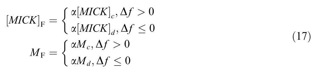
3.2 Hybrid energy storage internal power allocation
To facilitate the flywheel energy storage system’s response to high-frequency components, the theoretical power command for the flywheel in PFR mode encompasses the command designated for the entire energy storage system following initial distribution, along with the adaptive coordination control command for the flywheel.The formula for calculation is as follows [26]:

To prevent the overcharging and over-discharging of the flywheel, a logistic regression function is employed as the independent variable to regulate the output of the flywheel, which is articulated as follows.
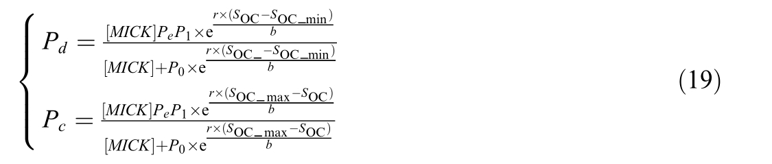

The actual charging and discharging power of the flywheel energy storage after the limiting module is.

To optimize the efficient output of pumped storage units, minimize unit degradation, and prioritize frequency control directives for flywheel energy storage systems, if the output is below the flywheel output threshold,pumped storage units are not required to compensate.If the output surpasses the flywheel output threshold,control strategy 1 module will implement constraints. The excess load that the flywheel cannot accommodate will be offset by the pumped storage units, with the compensation amount determined by the following formula:

The actual response component of pumped storage is:

The components of the actual response of the flywheel is:

4 Hybrid energy storage output control strategy based on FNN
4.1 The principle of FNN
A FNN is a hybrid intelligent system that integrates fuzzy logic with artificial neural networks. By integrating the rules and membership functions of fuzzy systems into the neural network architecture, the system utilizes the adaptive learning abilities of neural networks to dynamically modify the parameters of fuzzy systems.The integration of fuzzy systems’uncertainty management with neural networks’ self-learning skills facilitates effective reasoning and decision-making in intricate, nonlinear, and ambiguous settings. The FNN classifier produces if-then rules,which are the logical decision rules of the FNN, derived from the relationships within the feature space established during the training phase. The regulations governing the adaptive FNN are articulated in pseudocode as follows[27,28]:

The control method based on the FNN designed in this paper has a training scheme similar to that of the neural network and the same performance as the fuzzy logic inference system. It is a FNN system with a simple structure and adaptive learning ability. After inputting a large amount of data, the neural network can self learn and adapt, rather than relying on expert experience or being arbitrarily given, thus improving the control accuracy.The structure of the FNN consists of a five
  layer feed
 forward neural network, as shown in the Fig. 5.
The first layer is the input layer, which mainly includes two nodes. Therefore, the input and output of the first layer neural network can be expressed by the following formula:


The second layer is the fuzzification layer,which represents the linguistic variable values of the input variables.Usually, there are n variables in the fuzzy set. Its function is to calculate the membership degrees of each input component belonging to the fuzzy sets of each linguistic variable value. It is used to determine the membership degrees of the input corresponding to different fuzzy linguistic values for fuzzy inference. If the membership function is a Gaussian function, then its expression is:
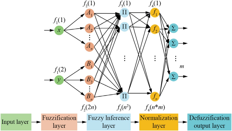
Fig. 5. FNN structure diagram.

The third layer is the fuzzy inference layer.Each node in this layer represents a fuzzy rule, and the output value of each node indicates the excitation intensity of each fuzzy rule. The expression of this node can be represented by the following formula.

The fourth layer is the normalization layer. Its output adopts the Mamdani fuzzy rule,and the expression of this layer is:
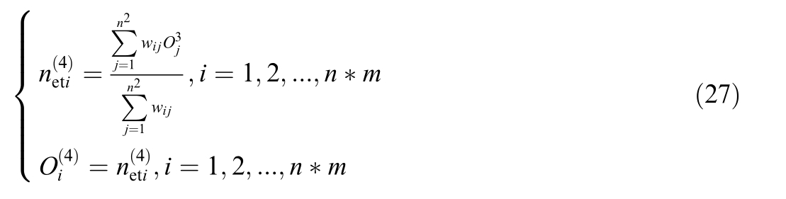
The fifth layer is the defuzzification layer of the FNN,that is,the process of making the output of the FNN crisp.


where: Srefrepresents the reference value of the state of charge, which is taken as 0.5 in this paper; Smax and Smin respectively represent the upper and lower limits of the state of charge.
4.2 Training of FNN
In this paper,5000 sets of data were extracted from the model built in SIMULINK for the training and testing of the FNN. The data were divided into a training set and a testing set at a ratio of 8:2. The inputs were the output of the HESS and SOC of the flywheel energy storage,and the output was the unit power regulation coefficient kof the energy storage. The controller parameters are shown in Table 1.
The membership degree of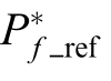 and
and after training is shown in the Fig. 6.
5 Simulation analysis
This study develops a two-region HESS frequency regulation model in MATLAB/Simulink. The system combines a 1000 MW traditional power plant with a pumped storage system that can adjust between ±40 MW and a FESS made up of 100 modules, each providing 200 kWof power and storing 5 kWh of energy. The FESS SOC was initialized at 0.5, with system parameters normalized to 1000 MW and 50 Hz base values. Simulation studies evaluated HESS performance under two disturbance regimes:step load changes and continuous load variations.Comparative analysis of system responses validated the proposed control strategy’s efficacy.
Table 1 Parameters of the FNN.
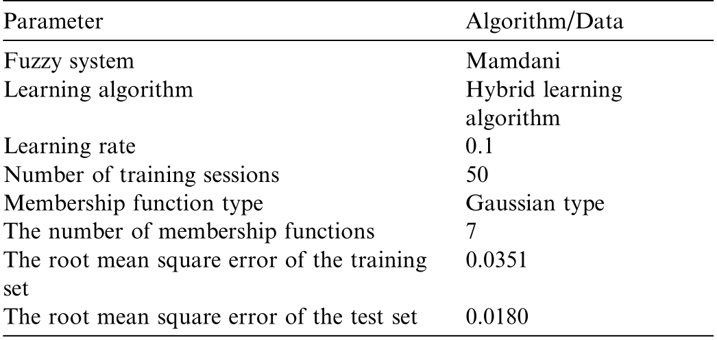
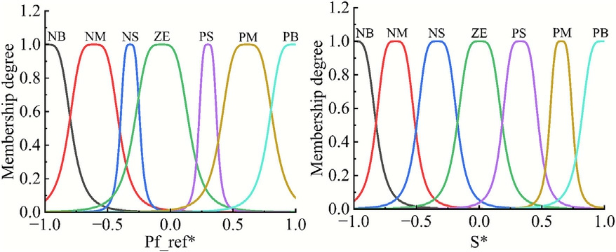
Fig. 6. The trained membership function.
For step load disturbances,the following characteristics are defined: the absolute maximum dynamic frequency deviation post-disturbance, the absolute steady-state frequency deviation,and the rate of frequency fall.The lower the value, the more significant the frequency regulation impact. A lower value indicates a greater capacity of the suggested model and associated strategy to maintain grid frequency stability, hence enhancing the stability of the grid’s frequency.
Continuous load disturbances are evaluated using three key metrics: frequency peak difference frequency deviation, and SOC deviation, quantified through root mean square (RMS) values. These metrics respectively indicate frequency stability,deviation magnitude from nominal frequency (50 Hz), and energy storage charge maintenance.Lower RMS values correspond to enhanced frequency regulation performance and improved SOC stability, as detailed in subsequent analysis.
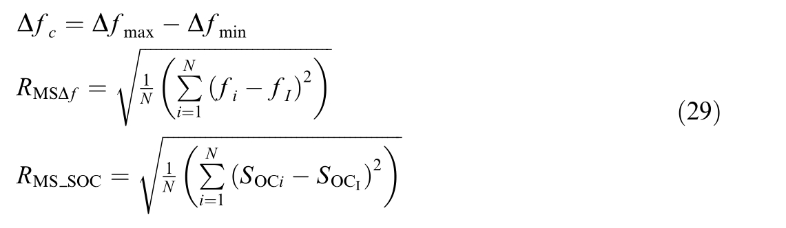
In the case that the system frequency distribution satisfies the mathematically preset normal distribution, the value of RMS Δf and RMS SOCreveals the dispersion of the system frequency distribution function. In other words,the smaller the value of, the smaller the difference in system frequency, which means the success rate of PFR is higher.
For power-induced fluctuations, the difference between the peak power and the overall power fluctuation is used to evaluate the smoothing performance under the corresponding energy storage control strategy. smaller the primary PFR effect is, the better it is.

5.1 Step perturbation simulation
In all figures of this paper, time/second is abbreviated as t/s.The disturbance scenarios employed in this paper are illustrated in Fig. 7, where Fig. 7(a) depicts a step disturbance and Fig. 7(b) shows a continuous disturbance.For the step disturbance, a load disturbance of 0.015 p.u. is introduced at t = 0.1 s; at t = 50 s, the load disturbance surges to 0.020 p.u.,with a total simulation duration of 150 s.As for the continuous disturbance,a random signal within the interval of [0.02, 0.02] is adopted.
Comparative simulations with step disturbances tested four setups:(1)Paper strategy,(2)FNN not used,(3)Constant sag control, and (4) Variable sag control. The proposed strategy’s frequency regulation performance was quantified through key metrics. Given the single-step disturbance profile, NRBO-VMD command decomposition was not implemented. Fig. 8 shows how the system responded in terms of: a) changes in frequency, b) power used for PFR by the thermal unit, c) power output from the flywheel energy storage, and d) changes in the flywheel’s SOC.
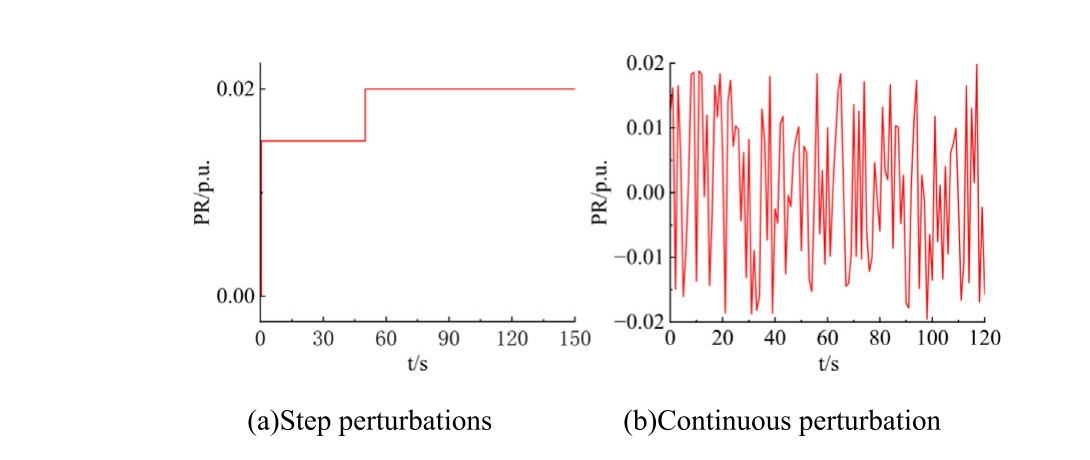
Fig. 7. Load disturbances.
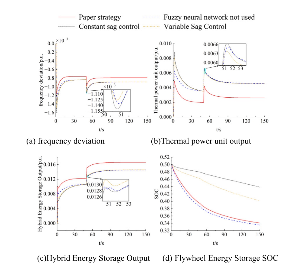
Fig. 8. Step perturbation simulation.
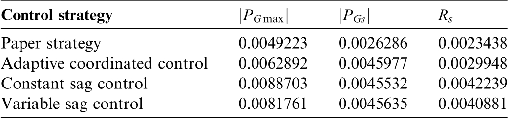
Table 2 Frequency evaluation indexes of the system under step perturbation.
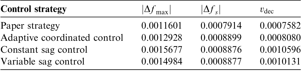
As illustrated in Fig. 8(a), a comparative analysis of control strategies reveals that the proposed method in this study significantly outperforms counterparts in mitigating frequency deviation, demonstrating a faster convergence to the steady-state condition. Table 2 presents the frequency evaluation metrics of the system under step disturbances, quantifying the performance improvements.Specifically, when looking at the adaptive coordinated control, the proposed strategy reduces the maximum frequency deviation by 10.08%, lowers the steady-state frequency deviation by 11.07%, and cuts the frequency deterioration rate by 10.08%. This enhanced performance is attributed to the FNN-based correction mechanism for the HESS output, which optimizes the frequency regulation capabilities.
Furthermore, the proposed approach exhibits even more pronounced advantages against traditional control methods. Compared with fixed droop control, it reduces the maximum frequency deviation by 26.12%, the steadystate frequency deviation by 10.84%, and the frequency deterioration rate by 28.44%.In the same way,when compared to variable droop control, the maximum frequency deviation,steady-state frequency deviation,and frequency deterioration rate are lowered by 22.67%, 10.85%, and 25.16%, respectively. These results collectively validate that the hybrid energy storage frequency regulation system under the proposed strategy effectively bolsters system frequency stability, providing a robust solution for power grid operation.
Fig. 8(b) illustrates the dynamic response of thermal power units to step disturbances. The results show that with the new control method,the output of thermal power units is greatly reduced, which helps lessen the frequency regulation demands on these units. This reduction in output implies enhanced operational flexibility and reduced mechanical stress on the thermal power generation equipment.
The Table 3 demonstrates that the proposed technique in this research yields improved peak output, stable output, and output smoothness of thermal power units compared to alternative control systems. In comparison to adaptive coordinated control, the peak output of thermal power units diminishes by 21.74%; relative to fixed droop control,it decreases by 44.52%;and in contrast to variable droop control, it is lowered by 39.80%. The stable output value of thermal power units diminishes by 42.83%relative to adaptive coordinated control,by 42.27%in comparison to fixed droop control, and by 42.40% versus variable droop control; the output smoothness of thermal power units declines by 21.74% compared to adaptive coordinated control, by 44.51% against fixed droop control,and by 42.67% in relation to variable droop control. This paper concludes that the proposed strategy diminishes the thermal power plant’s output demand during PFR by fully utilizing the benefits of flywheels, which offer high output power and rapid response, thus alleviating the frequency regulation burden on thermal power plants.
Fig. 8c and d present the Hybrid Energy Storage Output and Flywheel Energy Storage SOC. The proposed strategy achieves maximized HESS power contribution with distinct phase-dependent characteristics:FESS dominates initial response while pumped-storage prevails during mid-late stages, demonstrating complementary coordination. The approach employs a FNN to optimize HESS power allocation and SOC regulation.This methodology maximizes frequency regulation capabilities while maintaining SOC within safe operating bounds, ensuring both operational effectiveness and storage device longevity.
5.2 Continuous disturbance simulation
In practical applications, frequency fluctuations typically present as continuous, irregular, and frequent variations. Therefore, it is essential to model the impact ofmixed energy storage on the primary PFR under conditions of continuous disturbance.
Table 3 Evaluation indexes of thermal power unit output.
Under continuous load disturbances,the study employs two comparative schemes. The first scheme compares the proposed strategy with scenarios without NRBO-VMD and with conventional fixed droop control, aiming to validate the effectiveness of NRBO-VMD in decomposing PFR commands and the performance of the proposed adaptive coordinated control strategy. The second scheme compares the proposed strategy with a configuration lacking the FNN,in order to specifically evaluate the contribution of the FNN in correcting the power distribution of the hybrid energy storage system.
The primary frequency control command is decomposed using NRBO-VMD, with the K and αvalues optimized using NRBO configured in VMD. The results of the breakdown in the Fig. 9. The modal components of VMD and NRBO, post-decomposition, are reconstituted and juxtaposed with the principal frequency control command. NRBO-VMD is more aligned with the PFR directive. In conclusion, decomposing the PFR power command through NRBO-VMD yields low-frequency commands that more accurately correspond to the reference values for frequency variations in actual thermal power plant responses, thereby effectively mitigating frequent output fluctuations during frequency regulation operations.
The first group of schemes is simulated, and the corresponding frequency deviation,thermal unit output,hybrid storage output and flywheel storage SOC are shown in Fig.10,and the evaluation indexes of frequency regulation are shown in Table 4.
The Fig.10(a)depicts the deviation change curve under continuous disturbance in Scheme I. Upon comparing the strategy delineated in this paper with the alternative devoid of NRBO-VMD, it is evident that the frequency deviation table exhibits diminished alterations following the implementation of command decomposition, signifying a swift frequency response and more pronounced effects on frequency difference regulation and recovery.The proposed technique exhibits a 22.08% reduction in maximum frequency deviation compared to the strategy lacking NRBO-VMD. In comparing the strategy devoid of NRBO-VMD with fixed droop control, it is noted that the maximum frequency deviation of the strategy lacking NRBO-VMD is diminished by 22.08% relative to fixed droop control. This signifies that the frequency regulation efficacy of the control procedures in Sections 3 and 4 of this work is greater.
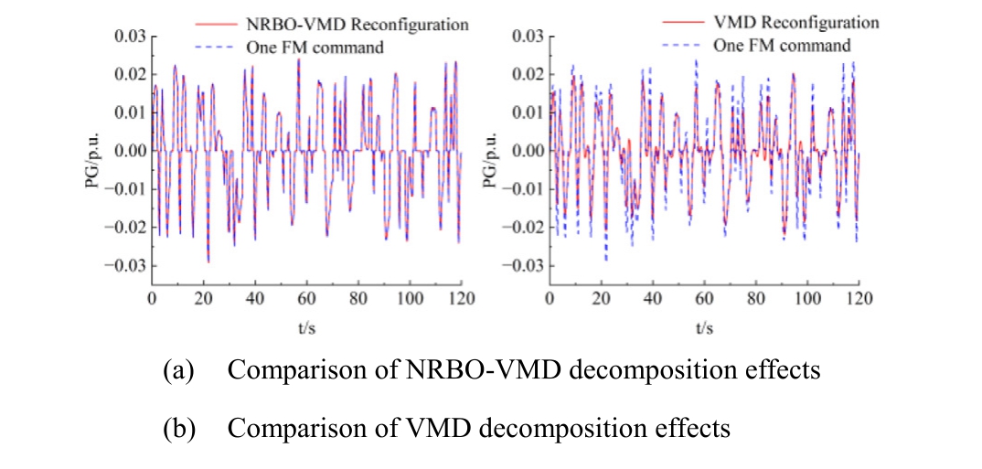
Fig. 9. Decomposition comparison chart.
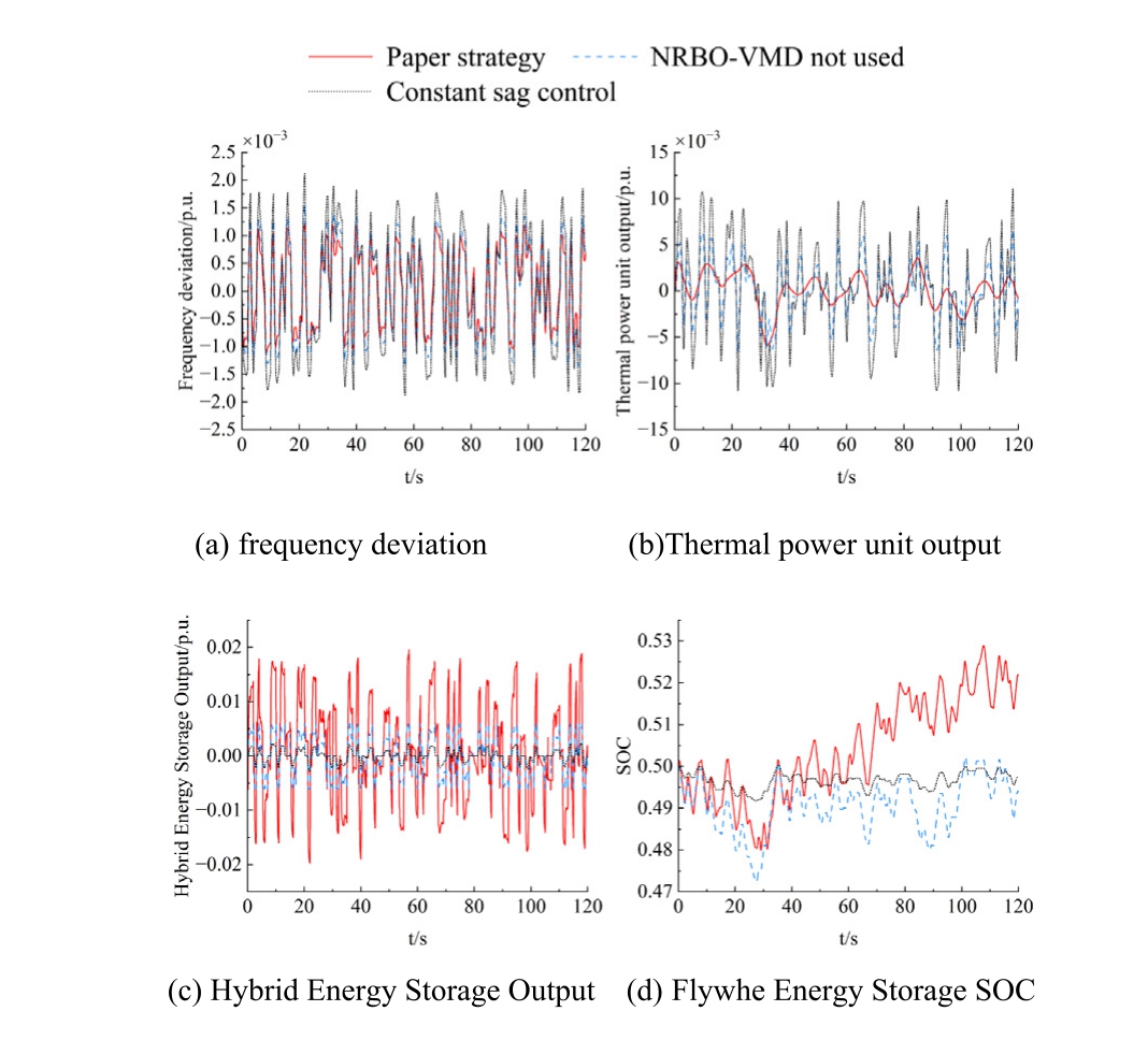
Fig. 10. Simulation analysis of scheme I.
Table 4 Indicators for evaluating the frequency deviation of option 1.

The Table 4 presents the evaluation indicators for frequency regulation in the context of continuous disruptions. The table illustrates that, under the method described in this research, the peak difference in PFR decreased by 57.24% compared to the scenario without NRBO-VMD, and the extent of frequency fluctuation diminished by 18.20%. In the scenario without NRBOVMD, the peak disparity in PFR diminished by 27.32%relative to fixed droop control,and the extent of frequency fluctuation decreased by 20.20%.The analysis clearly indicates that the control approach presented in this paper has enhanced efficacy in frequency regulation.
The Fig. 10(b) depicts the output curve of a thermal power plant experiencing continuous disturbance in Scheme 1. The comparison between the approach presented in this study and the one excluding NRBO-VMD illustrates that the thermal power unit’s output is diminished and the fluctuations are more stable following the implementation of command decomposition, hence mitigating wear and tear on the unit.This occurs because,following command decomposition, the HESS addresses the high-frequency components, and the thermal power plant addresses the low-frequency components. This mitigates variations in the thermal power plant’s output and mechanical degradation of the turbine, hence enhancing operational stability and overall economic efficiency of the facility. Comparing the results without NRBO-VMD and fixed droop control reveals that the thermal power plant’s output is diminished in the absence of NRBOVMD, hence illustrating the efficacy of the control methodologies presented in Sections 3 and 4 of this work.
The Table 5 presents the performance evaluation metrics for thermal power units. The table illustrates that the strategy presented in this paper achieves a 29.13%reduction in power peak difference compared to the scenario without NRBO-VMD, alongside a 29.02% decrease in power fluctuation. Furthermore, in the absence of NRBO-VMD, the power peak difference is diminished by 39.26% relative to fixed droop control, with frequency fluctuation reduced by 45.40%.This further illustrates that the technique presented in this paper significantly alleviates the frequency regulation burden on thermal power units.
The Fig. 10(c) and (d) depicts the output of hybrid energy storage and variations in flywheel SOC during sustained disturbance in Scheme 1. The figure illustrates that the proposed technique results in a larger output for the HESS,while the SOC variation in the flywheel energy storage system is the most significant. This signifies that the flywheel energy storage system exhibits increased output frequency, more variability, and enhanced flexibility. This further illustrates that the strategy outlined in this paper not only capitalizes on the flywheel energy storage system’s extensive charge/discharge cycles but also optimizes its frequency regulation capacity to address system frequency fluctuations, leading to enhanced efficiency in the utilization of this capacity.
The second set of scenarios is simulated and the corresponding frequency deviation, hybrid storage output and flywheel storage SOC are shown in Fig. 11.
The Fig.11(a)depicts the deviation change curve under continuous disturbance in Scheme 2. The figure illustrates that, in contrast to the approach devoid of FNN, the frequency deviation of the technique presented in this research is reduced. The maximum frequency deviation of the strategy presented in this paper is diminished by 31.82% compared to the strategy that does not employ FNN, and the frequency fluctuation is decreased by6.37%, demonstrating that the application of FNN for hybrid energy storage power correction significantly enhances frequency regulation efficacy.
Table 5 Indicators for evaluating the output of thermal power units in Scheme 1.

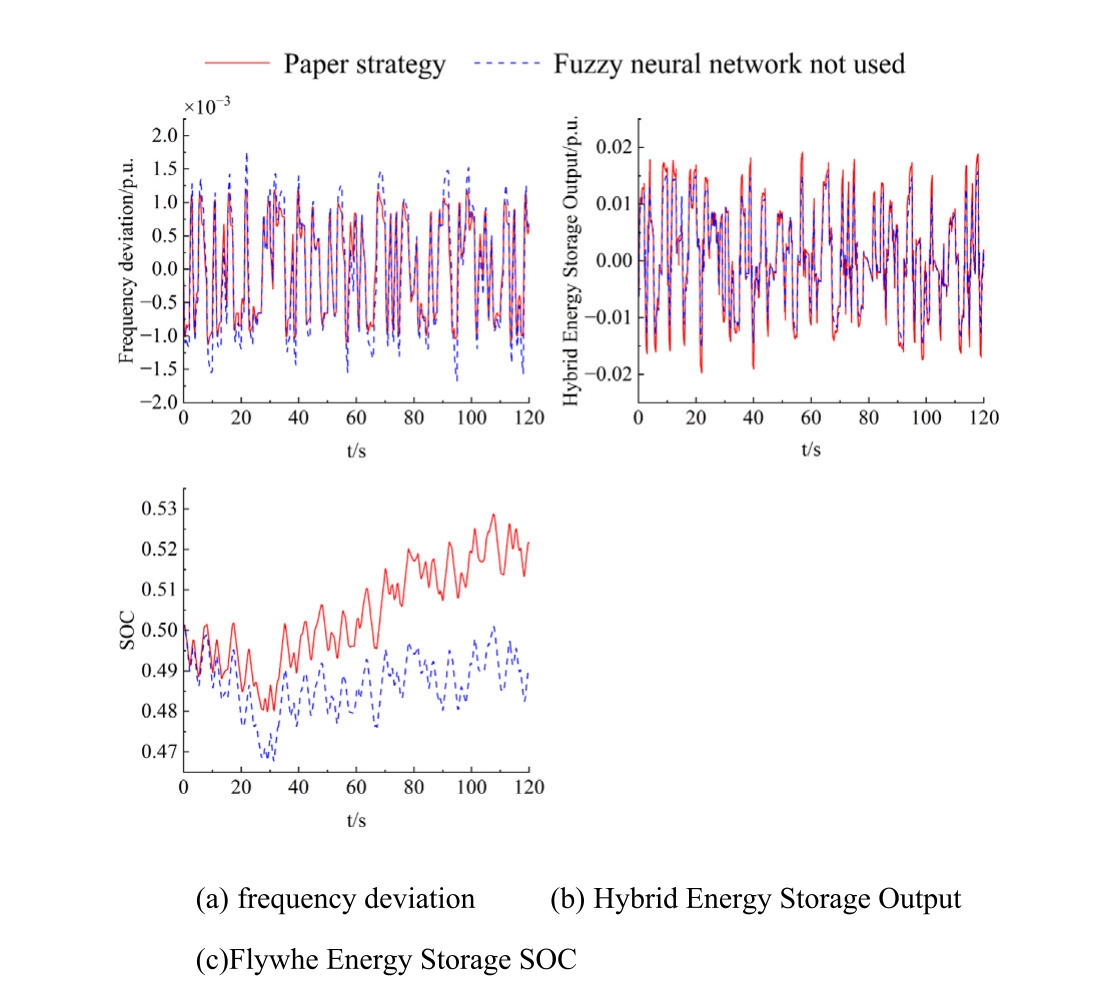
Fig. 11. Simulation analysis of scheme II.
The Fig. 11(b) and (c) depicts the output of the HESS and the SOC variations of the flywheel under persistent disturbances in Scheme 2. The figure illustrates that the hybrid energy storage output under the technique presented in this paper is superior.The FNN can dynamically alter the hybrid energy storage output in real-time according to the SOC to enhance frequency regulation performance. The alterations in SOC indicate that the enhancement in SOC following power rectification via the FNN is markedly greater. Consequently, the selfrecovery capacity of the SOC under the technique defined in this work is significantly augmented.
6 Conclusion
This paper addresses the issue of increased frequency regulation burden on thermal power units due to the high proportion of renewable energy integration. A primary frequency regulation control strategy involving hybrid energy storage systems based on NRBO-VMD and FNN is proposed. Simulation analysis leads to the following conclusions:
This paper mainly focuses on the control strategy for hybrid energy storage participating in PFR and does not explore the optimal capacity configuration of hybrid energy storage, which remains to be further investigated in future work.CRediT authorship contribution statement
Ping Zhang:Conceptualization,Methodology,Supervision. Ming Zhi Li: Writing – original draft. Chang Sheng Jiao:.
Declaration of competing interest
The authors declare that they have no known competing financial interests or personal relationships that could have appeared to influence the work reported in this paper.
Acknowledgments
This work was supported by the Lanzhou Science and Technology Plan Project (XM1753694781389).
References
[1]Y.Zhang,Y.Zhang,T.Wu,Integrated strategy for real-time wind power fluctuation mitigation and energy storage system control,Global Energy Interconnect. 7 (1) (2024) 71–81.
[2]H. Li, D. Liu, D.Y. Yao, Analysis and reflection on the development of power system towards the goal of carbon emission peak and carbon neutralit, Proc. CSEE 41 (18) (2021)6245–6259.
[3]Y. Shi, Y. Cheng, B. Xie, et al., An adaptive control strategy for microgrid secondary frequency based on parameter identification,Global Energy Interconnect. 6 (5) (2023) 592–600.
[4]Z.H.A.N.G. Ziyang, Z.H.A.N.G. Ning, D.U. Ershun, et al.,Review and countermeasures on frequency security issues of power systems with high shares of renewables and power electronics, Chin. J. Electr. Eng. 42 (01) (2022) 1–25.
[5]Y.V. Makarov, P.W. Du, M.C.W. Kintner-Meyer, et al., Sizing energy storage to accommodate high penetration of variable energy resources, IEEE Trans. Sustain. Energy 3 (1) (2012) 34–40.
[6]D.W. Su, Y.C. Hao, S.P. Gao, et al., Grid emergency frequency control method based on energy storage inertial response,J.Global Energy Interconnect. 6 (6) (2023) 640–649.
[7]J. Zou, X. Lai, N.B. Wang, Study on control of pumped storage units for frequency regulation in power systems integrated with large-scale wind power generation, Proc. CSEE 37 (2) (2017) 564–572.
[8]L. Ye, K.F. Wang, Y.N. Lai, et al., Review of frequency characteristics analysis and battery energy storage frequency regulation control strategies in power system under low inertia level, Power Syst. Technol. 47 (2) (2023) 446–464.
[9]L.He,L.Q.Guo,Z.X.Tan,et al.,Comprehensive control strategy of hybrid energy storage in primary frequency regulation considering demands of frequency regulation stages, Acta Energ.Sol. Sin. 45 (9) (2024) 697–708.
[10]X.S. Yan, Z.W. Liu, J.H. Zhao, et al., Primary frequency regulation and capacity configuration of hybrid energy storage auxiliary thermal power unit, Acta Energ. Sol. Sin. 45 (11) (2024)647–654.
[11]C.F. Wang, L. Wang, F.F. Sun, et al., Two-layer optimal configuration model of hybrid energy storage assisted wind power frequency regulation based on fuzzy logic control, High Volt. Appar. 60 (10) (2024) 54–63.
[12]X.R. Li, X.W. Cui, J.Y. Huang, et al., The self-adaption control strategy of energy storage batteries participating in the primary frequency regulation,Trans.China Electrotech.Soc.34(18)(2019)3897–3908.
[13]X. Deng, W. Sun, H.W. Xiao, Integrated control strategy of battery energy storage system in primary frequency regulation,High Volt. Eng. 44 (4) (2018) 1157–1165.
[14]Y.R. Sui, S.Y. Liang, D.C. Huang, et al., Simulation study on frequency modulation process of coal burning plants with auxiliary of flywheel energy storage, Proc. CSEE 40 (8) (2020) 2597–2606.
[15]F.Hong,L.Liang,Y.L.Pang,et al.,Primary frequency regulation of flywheel energy storage combined thermal power unit based on adaptive coordinated droop control,Thermal Power Gener. 52(1)(2023) 36–44.
[16]C.F. Wang, L. Wang, F.F. Sun, et al., Two-layer optimal configuration model of hybrid energy storage assisted wind power frequency regulation based on fuzzy logic control, High Voltage Appar. 60 (10) (2024) 54–63.
[17]S.P. Zhang, P.Q. Li, Y.J. Zhang, et al., Secondary frequency modulation strategy of composite energy storage based on variable filter time constant and fuzzy control,J.Shanghai Jiao Tong Univ.59 (9) (2025) 1370–1382.
[18]S.R. Liu, P.Q. Li, J.Y. Chen, et al., Allocation of hybrid energy storage capacity based on Pearson correlation analysis and T-tFD algorithm under VMD decomposition,Electric Power 57(7)(2024)82–97.
[19]L. Wu, P. Chang, W. Chen, et al., Generalized load graphical forecasting method based on modal decomposition,Global Energy Interconnect. 7 (2) (2024) 166–178.
[20]R. Sowmya, M. Premkumar, P. Jangir, Newton-Raphson-based optimizer: a new population-based metaheuristic algorithm for continuous optimization problems, Eng. Appl. Artif. Intel. 128(2024) 107532.
[21]G.G.Yan,Y.Y.Li,Q.L.Sha,et al.,Co-control strategy for hybrid storage-assisted thermal power unit frequency regulation based on ICEEMDAN decomposition, Power Syst. Technol. (2025) (in press).
[22]Z.H.Liu,Control Strategy of Hybrid Energy Storage Participating in Frequency Modulation Based on Fuzzy Neural Network,Shenyang Institute of Engineering, 2024.
[23]B. Li, M.Y. Chen, H.W. Zhong, et al., A review of long-term planning of new power systems with large share of renewable energy, Proc. CSEE 43 (2) (2023) 555–581.
[24]S. Wu, X.Y. Bian, J.X. Zhang, et al., A review of domestic and foreign ancillary services market for improving flexibility of new power system, Trans. China Electrotech. Soc. 38 (6) (2023) 1662–1677.
[25]K.F. Wang, L.R. Xie, Y. Qiao, et al., Analysis of improving frequency modulation performance of power system by battery energy storage,Autom.Electric Power Syst.46(1)(2022)174–181.
[26]X. Han, Z.W. Liu, X.D. Wang, et al., Flywheel energy storage assists thermal power unit frequency regulation simulation, Acta Energ. Sol. Sin. 45 (7) (2024) 163–171.
[27]M.Ding,G.D.Lin,Z.N.Chen,et al.,A control strategy for hybrid energy storage systems, Proc. CSEE 32 (07) (2021) 1–6.
[28]M.Ding,Z.Tao,B.Hu,et al.,A fuzzy control and neural network based rotor speed controller for maximum power point tracking in permanent magnet synchronous wind power generation system,Global Energy Interconnect. 6 (5) (2023) 554–566.
Received 28 June 2025; accepted 11 September 2025
Peer review under the responsibility of Global Energy Interconnection Group Co. Ltd.
* Corresponding author
.
E-mail address: 3252644030@qq.com (M.Z. Li).
https://doi.org/10.1016/j.gloei.2025.09.005
2096-5117/ 2026 Global Energy Interconnection Group Co. Ltd. Publishing services by Elsevier B.V. on behalf of KeAi Communications Co. Ltd.
This is an open access article under the CC BY-NC-ND license(http://creativecommons.org/licenses/by-nc-nd/4.0/).

Ping Zhang received her Ph.D. degree at Lanzhou University of Technology, Lanzhou,China, in 2012. She is a professor and masters supervisor in the College of Automation and Electrical Engineering. Her research interests include modeling and control of If new energy power systems.