
0 Introduction
With the advancement of China’s urbanization,the use of medium-voltage cables has increased significantly.Cable faults causing power outages have severely affected the reliability of urban distribution network operations,with cable-joint faults being particularly prominent.Recent studies have revealed that some cable joints experience a single self-clearing and self-restoring discharge within one cycle prior to a permanent fault [1].This phenomenon,referred to as a sub-cycle incipient fault (hereafter termed “incipient faults”),can develop into a permanent fault.Accurate identification of incipient faults is essential to preventing losses associated with permanent fault-induced power outages.
Researchers have investigated incipient faults from two main perspectives: (1) identification methods based on the external circuit equivalent model,and (2) simulation experiments under varying conditions such as sand,rainfall,and high temperature.Kim simulated the circuit of a self-clearing incipient fault to examine location methods[2].Wu employed a style="font-size: 1em; text-align: justify; text-indent: 2em; line-height: 1.8em; margin: 0.5em 0em;">To address the issue of limited understanding of the development process of sub-cycle incipient faults in existing research,this study first summarizes the initial fault scenario based on the actual operating conditions of cable joints.On this basis,a simulation experiment of sub-cycle incipient faults was conducted,during which variations in electrical and non-electrical quantities were observed.Subsequently,surface morphology ob servations and elemental spectrum analyses were performed on the post-experiment samples.By integrating these observations,the study analyzes the development process of sub-cycle incipient faults and the relationship between electrical and non-electrical quantities throughout this process.
1 Experiment description
1.1 Operating scenario analysis
During cable-joint installation,sharp corners in the conductor or semi-conductive layer can induce dendritic aging within the insulation [6].Bending or external mechanical damage to the cable joint may also generate voids within the main insulation.Previous experiments indicate that if the inner wall of such a void has not undergone discharge aging or contamination,it can retain a certain level of insulation.Under these conditions,when a 10 kV single-phase-to-ground voltage of 5.8 kV is applied across the main insulation,arc discharge occurs only with a certain probability.
Existing research indicates that,in the absence of water,an increase in humidity alone does not reduce environmental insulation strength[7].However,cable trenches,cable wells,and surrounding soil are susceptible to precipitation and often contain water.If voids formed during early-stage damage are exposed to water from sources such as flooding,rainfall,or condensation,sub-cycle incipient faults may occur.
1.2 Experimental platform
Based on the analysis in Section 1.1,an incipient fault simulation platform was developed to replicate the actual operating environment of the cable.The experimental cable is a three-core copper conductor with a crosssectional area of 50 mm2,a configuration commonly used in distribution networks.Actual devices were used as experimental samples.The cable joint is a coldshrinkable-type silicone rubber,the most commonly used in China’s distribution networks.Its structure is shown in Fig.1.
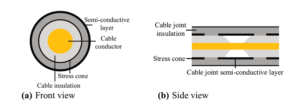
Fig.1.Structure of the cable joint.
For a cable joint experiencing a single-phase ground fault,the line structure at the fault point is shown in Fig.2 [8].As the fault grounding circuit and the load are connected in parallel,they do not affect each other;therefore,in the experiment,the circuit connected to the load beyond the fault point can be ignored.
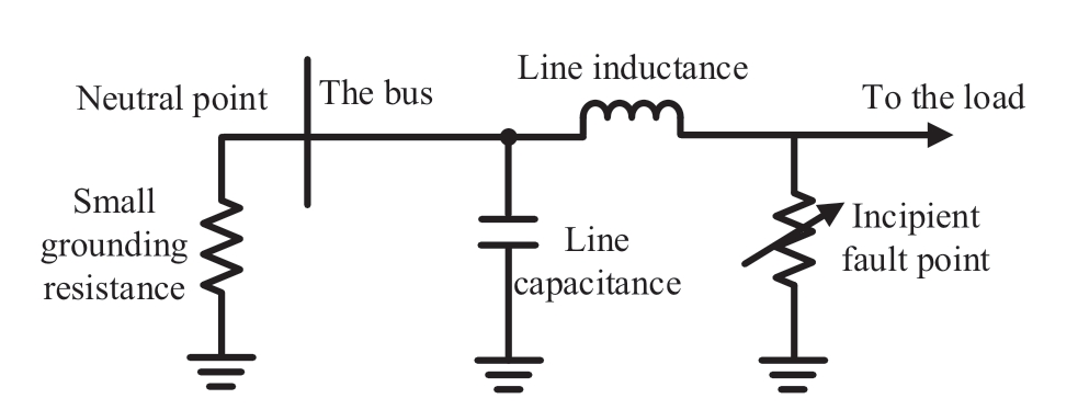
Fig.2.Fault location in the distribution network.
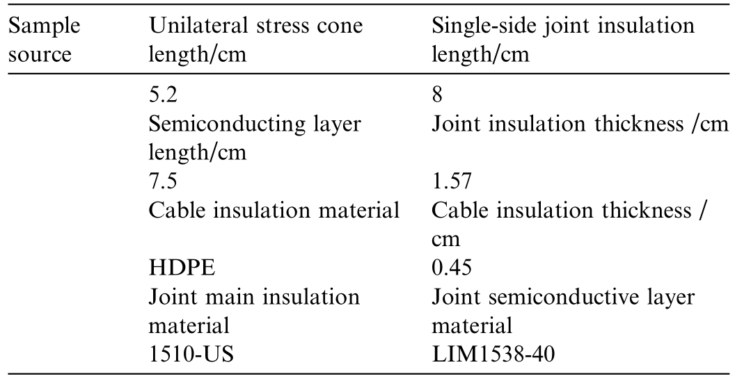
Before the experiment,an intact cable joint was used to connect two 70-cm-long cable sections.Further,5 cm of insulation and semiconductive layers were removed from both ends to expose the conductors as terminal points.Additionally,10 cm of the semiconductive layer,starting from the conductor end,was removed to prevent unintended flashover between the conductor end and the semiconductive layer during the experiment.The detailed sample parameters are listed in Table 1.
Table 1 Parameters of experimental samples.
Two sets of control experiments were conducted in this study.First,to simulate defects in different positions of the cable joint caused by external force damage or by sharp corners in the semi-conductive layer [9],pores of identical diameter but different depths were introduced at various locations of the cable joint under the same conditions.The processed samples are shown in Fig.3,and the pore dimensions at each location are listed in Table 2.Additionally,to investigate the degradation of insulation performance in cable joints due to the progression of incipient faults,the appearance of the same sample was examined after different discharge durations.
Table 2 Depths of different pores.
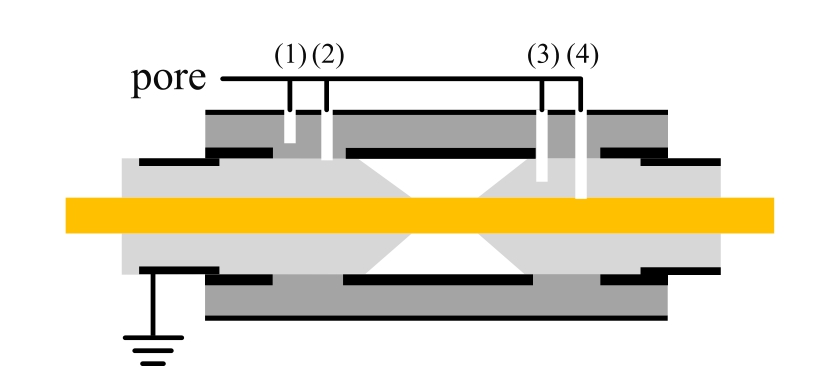
Fig.3.Fault location in the distribution network.
1.3 Experimental circuit and equipment
Fig.4 depicts the experimental circuit for incipient fault testing.The power supply operated at a frequency of 50 Hz and was connected through an isolation transformer.The primary side of the transformer had an effective voltage of 35 kV,and the secondary side operated at 10 kV.The grounding line was connected through a 20 Ω resistor,consistent with common practice in distribution cable networks.A 1000 Ω current-limiting resistor was connected in series in the secondary circuit to prevent the impact of high currents on the power grid during the experiment.Additionally,the circuit incorporated a series connection of an equivalent RLC combination representing 5 km of overhead lines and 5 km of cable lines,simulating urban distribution network configurations that utilize both.
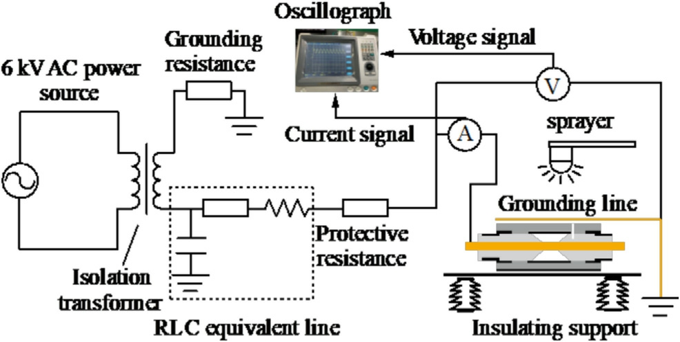
Fig.4.Structure of the experimental sample.
The internal arrangement of the testing box is illustrated in Fig.4.The experimental samples were placed on insulating supports,with only one exposed conductor end connected to the current-limiting resistor.Given the negligible circuit load,the exposed conductor at the other end was immersed in an insulating oil tank.The semiconductive layer of the cable immersed in the oil tank was connected to the grounding point.A cable joint with pre-drilled pores was installed on the connected cable and wrapped with a clean copper mesh to restore the normal grounding condition of the cable joint.The insulating bracket and samples were placed in a temperature and humidity-controlled chamber maintained at 20 °C and 90% relative humidity.Locally sourced tap water,with a measured conductivity of approximately 0.05 S/m,was used in the experiment.A sprayer installed directly above the bracket delivered water at a rate of 2 mL/s to precisely simulate conditions inside a cable,targeting the side of the cable joint containing the pores.The droplets covered the pore area.
An MR-1200 oscillograph was configured with a sampling frequency of 10 kHz and an A/D resolution of 16 bits for data collection.The voltage measurement range was 0–10 kV,and the current measurement range was 0–1 A.The oscilloscope’s current probe was connected in series between the voltage source and the cable terminal point to measure the current through the fault point.The voltage probe was connected between the cable terminal point and the cable grounding line to measure the voltage across the sample.
A confocal micro-Raman spectrometer (Renishaw) with a laser wavelength of 785 nm and a maximum output power of 100 mW was used to analyze the gradients of the sample.The sample stage had an accuracy better than 0.01%.The spectrograph featured a 300 mm focal length,a spectral resolution better than 1 cm 1,and a minimum measurement time of 0.76 ms.
1.4 Experimental procedure
1) Place the experimental sample in the temperature and humidity-controlled chamber and connect it to the power supply.Position the side containing the pore directly upward,ensuring that the pore designated for testing faces the sprayer above.Adjust the sprayer to cover a circular area with a radius of approximately 2 cm at a flow rate of 3 mL/s,without affecting pores not involved in the experiment.
2) Switch on the power supply and activate the sprayer to cover the specified circular area as described.Simultaneously monitor the oscillograph and highspeed camera to detect any current amplitudes or phenomena distinctly different from partial discharge,as well as self-clearing flashes during arc discharge.If such phenomena occur,record the observations and fault characteristics,and then deactivate the sprayer.
3) If arc discharge does not occur in step 2),turn off the power supply,adjust the position of the experimental sample,and repeat step 2).If a particular pore fails to exhibit discharge after five consecutive attempts,proceed to the next pore.
4) For samples exhibiting discharge phenomena in step 2),repeat steps 1)– 3).If a sample exhibits a sustained,high-intensity arc discharge lasting several seconds or longer without self-clearing,classify it as a permanent fault.Stop the experiment and replace the sample.
2 Results and discussion
2.1 Analysis of experimental phenomena
After powering on and before activating the sprayer,no arc discharge occurred in the pores of varying depths within the cable joint.This indicates that even when gaps are present in the main insulation owing to external forces or internal stress concentration,their length is still suffi-cient to prevent direct breakdown of the cable joint.
Upon activating the sprayer,no arc discharge was observed in pores that did not penetrate the main insulation,or in those that penetrated the main insulation but did not damage the cable insulation.Specifically,pores(1) and (2) exhibited no discharge,wher eas pores (3) and(4) showed discharge.These results demonstrate that intact cable insulation can prevent arc discharge even when the cable joint itself is damaged by external forces.
For pores (3) and (4),prior to breakdown,the accumulation of water on the surface and within the internal pores of the cable joint led to continuous corona discharge in the discharge-prone pores.The discharge remained relatively weak and did not form a distinct arc.As the water content increased further,the discharge intensity gradually increased,eventually producing a noticeable arc discharge.At breakdown,a brief spark and the release of water vapor from the pores are externally visible between the copper grounding shield connected to the grounding line and the surface of the cable joint,as shown in Fig.5.The discharge then ceased spontaneously without external interventi on,constituting an incipient fault.
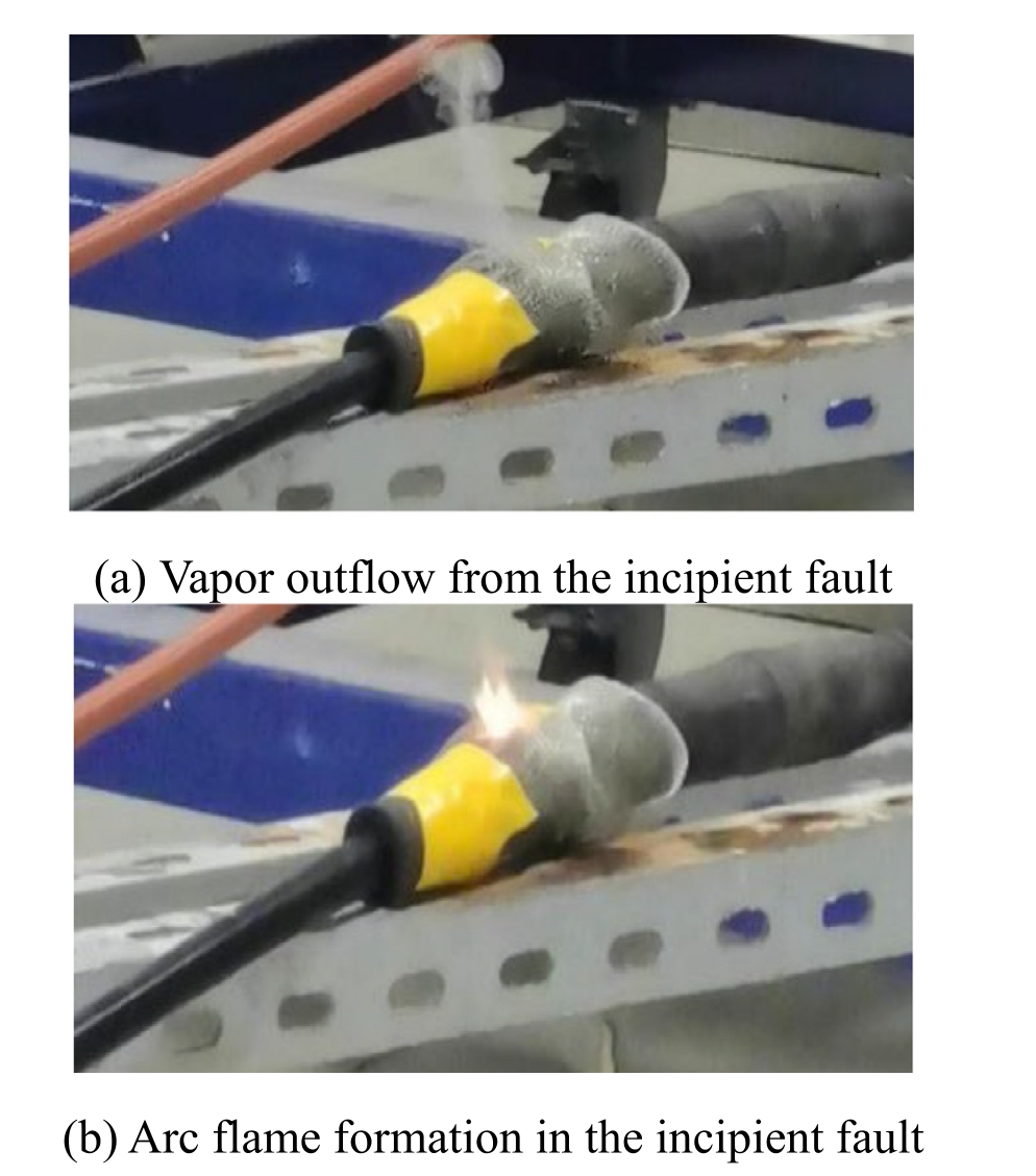
Fig.5.Vapor release and arc flash during a sub-cycle incipient fault.
After discharge,the insulation surface exposed to the arc exhibited gray-white and black roughened areas compared to the insulation that had not experienced an incipient fault.The pore diameters were larger than they were before the discharge.Additionally,the insulation surface temperature increased significantly,and all water within the pores evaporated completely.
After the arc was extinguished,precipitation and condensation caused moisture to re-enter the pores formed by previous damage,creating conditions conducive to incipient faults.In the experiment,rep eated triggering of incipient faults eventually led to a non-self-clearing subsequent discharge,leading to a permanent fault.Fig.6 depicts the arc flame during a permanent fault.At this stage,the discharge intensity far exceeded that observed during the incipient fault phase.The resulting flame penetrated the copper grounding shield of the cable joint and reached heights exceeding 10 cm.The flame tip exhibited a green color,indicating the presence of copper particles based on flame color reactions.During discharge,occasional sparks containing solid particles detached from the flame tip,accompanied by dense,sustained smoke.This suggests that the arc root temperature exceeded the melting point of copper,causing vaporization of the cable’s copper conductor.The resulting copper vapors were transported to the flame tip by the arc’s airflow.
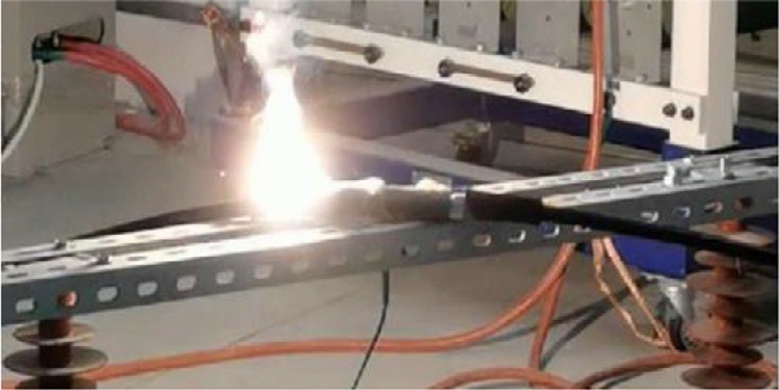
Fig.6.Arc formation in the permanent fault.
2.2 Electrical characteristics of incipient faults
Fig.7 presents a typical voltage and current waveform of an incipient fault.With the inclusion of a currentlimiting resistor,the peak current reached 4–5 A.Rough estimations suggest that in actual power grid scenarios,the peak current during an incipient fault may range from hundreds to several thousand amperes.Defining the total discharge duration as the fault presence time,the discharge starts approximately halfway through the rising section of the voltage cycle’s absolute value and ends before the voltage amplitude crosses zero,lasting between 1/8 and 1/4 of a cycle.At discharge onset,a sharp voltage drop occurs across the fault point,typically to a few hundred volts.This process lasts ap proximately 0.002 s and corresponds to the initial rise followed by the subsequent decline of the current amplitude.As the current amplitude decreases further,the voltage waveform at the fault point rebounds and eventually returns to a sinusoidal form.This phenomenon indicates that during an incipient fault,the fault resistance increases,suggesting a temporary enhancement in the insulation strength of the environment.The incipient fault phenomena observed in the experiment are consistent with previous research findings [10–12].
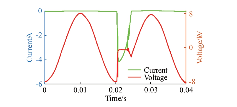
Fig.7.Current waveform of the sub-cycle incipient fault.
Fig.8 illustrates the variation in fault impedance during the sub-cycle incipient fault shown in Fig.7.At fault inception,the ground current transitions from leakage current to arc current,causing a sudden drop in circuit impedance.At t=0.021 s,the impedance reaches its minimum value of 134.4 Ω.During the fault period,the impedance remains relative ly stable,measuring 123.48 Ω at t=0.023 s.As the fault nears termination,the impedance rises rapidly,reaching 1101 Ω at t=0.024 s,and 109,862 Ω at t=0.025 s.
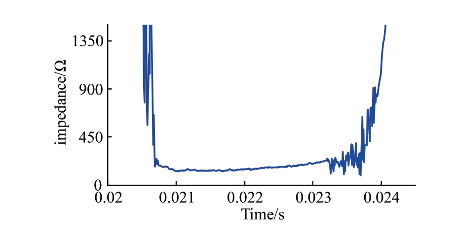
Fig.8.Impedance change during the sub-cycle incipient fault.
A permanent fault develops after several occurrences of incipient faults.Fig.9 shows the current and voltage waveforms at the onset of a permanent fault.Permanent faults appear as continuous arc discharges on a second-scale and as intermittent discharges with certain “zero-rest” periods on the millisecond scale.During the fault process,and excluding the effects of external circuit capacitance and inductance,the growth and decay trends of the fault current parallel those of the voltage but exhibit a higher rate of change over the same period.The current variation displays a nonlinear pattern that closely approxima tes a sinusoidal waveform.
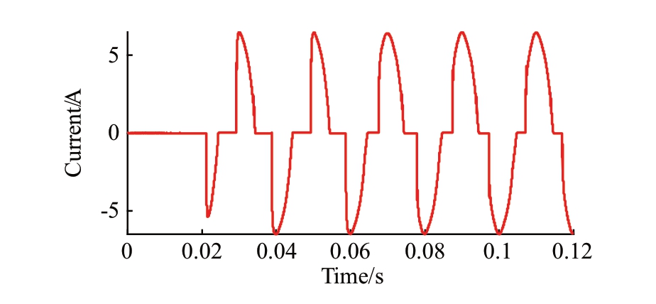
Fig.9.Current waveform at the onset of the permanent fault.
Permanent faults also undergo a development process.Fig.10 shows the current waveform after a permanent fault has persisted for a certain duration: (a) represents the waveform 3 s after the onset of the permanent fault,as shown in Fig.9,and (b) represents the waveform 3.5 s after the onset of the permanent fault.The figure illustrates that,as the fault progresses,the current waveform becomes increasingly continuous [13].
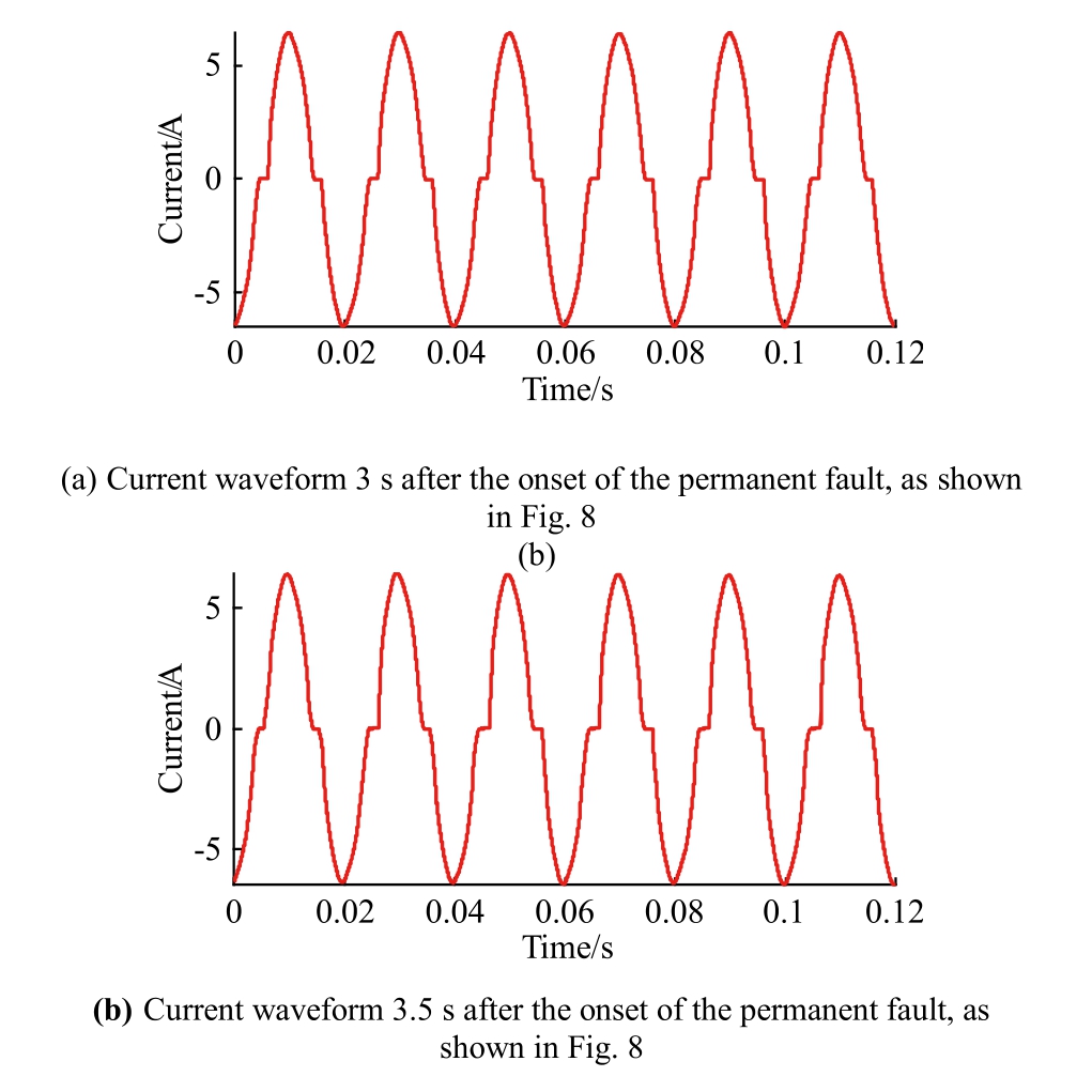
Fig.10.Current waveform of the fully developed permanent fault.
To quantify the degree of current continuity in this process,the “zero rest cycle” X is defined.For an incipient fault current signal If containing n signal points,the numerical solution is obtained as follows:
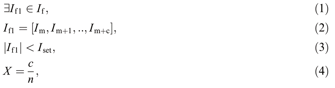
where [Im,Im+c,,Im+c]represents the amplitudes of each peak point within the If1 segment signal,Im is the current amplitude at the starting point of the If1 signal,and Iset is the current threshold for determining zero-rest,which is nonzero due to the presence of environmental leakage current.c den otes the number of signal points in the If1 signal with amplitudes less than Iset.Based on calculations,the average zero-rest cycle in Fig.9 is 37.4%,whereas the zero-rest cycles in Fig.10(a) and (b) are 12.8% and 13.9%,respectively.As the discharge process continues,the zero-rest ratio gradually decreases over a long time scale but exhibits certain randomness over a short time scale.This indicates that,compared with the onset of a permanent fault,the arc is more likely to reignite during subsequent discharges,and the insulation performance of the air in the arc area improves as the discharge progresses.
Comparing the impedance values at the peak of the last positive half-cycle of the voltage in Figs.9 and 10(a),and(b),the impedance values including the protection and line resistances are 1273.08,1272.28,and 1295.19 Ω,respectively.Excluding the protection and line resistances,the corresponding values are 263.97,263.18,and 286.09 Ω.According to current research,this phenomenon occurs because the high temperature of the arc heats the air in the arc channel,increasing its temperature,which leads to further ionization of the air and a rapid increase in its conductivity[14].This process reduces the difficulty of discharge initiation and,combined with increased discharge intensity,creates a positive feedback loop that accelerates the development of permanent fault s.Additionally,metal vapor generated during discharge further enhances air conductivity,making the arc more prone to reignite [15].However,turbulence caused by the high-temperature arc gases introduces randomness and fluctuation into the process [16].
The grounding impedance of incipient faults is relatively low.Because the impedance of an incipient fault does not significantly differ from the line impedance,the distance between the fault point and the outgoing line affects the fault characteristics to some extent.As the fault point moves farther from the outgoing line,the incipient fault current tends to decrease.
2.3 Non-electrical characteristics of incipient faults
During the early stages of fault development,the influence of individual incipient faults on environmental factors,such as air composition,is minimal owing to their short duration.However,the arc generated by an incipient fault still erodes the insulating surfaces at the contact area.These surface changes constitute the primary nonelectrical characteristics of incipient faults.
Fig.11 shows the cable joint after the initial incipient fault.As illustrated,the copper mesh facing the pore of the cable joint fractured following discharge.In the arc tip area,the copper shielding mesh was burned,whereas in the arc edge area,the aluminum coating on the copper shielding mesh faded owing to lower temperatures.This fading indicates that the temperature at the arc tip exceeds the melting point of aluminum.
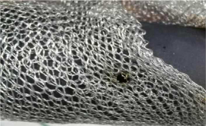
Fig.11.Appearance of the sample after the first incipient fault.
Fig.12 illustrates the cable joint after three incipient faults.Compared with the first incipient fault,the fracture area of the copper shielding mesh expanded significantly.During discharge,the pore area also enlarged,forming an outwardly piled,ring-shaped,multilayered crack with crystalline deposits.The outer semiconductive layer of the cable joint,initially intact before discharge,was also damaged and hardened.In the lower-temperature arc edge region,the aluminum coating melted,exposing the underlying copper conductor.These observations indicate that as incipient faults progress,discharge intensity increases and the high-temperature arc region expands.
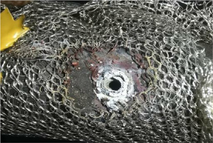
Fig.12.Appearance of the sample after three incipient faults.
A single incipient fault causes relatively limited and controllable insulation damage,whereas a permanent fault results in rapid and severe deterioration of the cable joint.Fig.13 illustrates the cable joint 5 s after the onset of a permanent fault.After several seconds of burning,the diameter of the discharge pore had expanded to the centimeter scale.Both the cable joint and the cable insulation layer inside the pore exhibited significant erosion and melting due to ablation.Numerous small black particles adhered to the inner pore surface and were deposited on the hardened insulation.
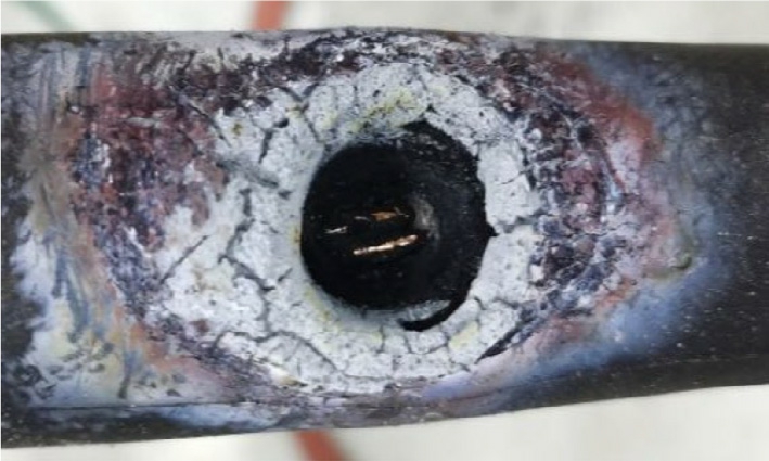
Fig.13.Appearance of the sample after the permanent fault.
Fig.14 presents the Raman spectra from different parts of the sample: (a) corresponds to black particles generated during discharge from the insulation of the cable joint(SIR),and (b) corresponds to the remaining SIR portions with no direct arc contact.As shown,the prominent bands of silicone rubber differ significantly between arc-affected and unaffected regions.In (b),the strong bands at 2850–2950 cm 1 correspond to the stretching of the–CH3 group,characteristic of the terminal groups of undamaged silicone rubber chains.In contrast,the arc-affected insulation in (a) exhibits two new promin ent bands at 1132–1450 and 1600–1651 cm 1 with higher relative intensity,whereas the original 2850–2950 cm 1 bands decrease in both absolute and relative intensity.According to existing studies,the range 1132–1450 cm 1 includes C=C double bonds of aliphatic hydrocarbons,C–O bonds of aldehydes,and other functional groups,whereas 1600–1651 cm 1 corresponds to C=C double bonds in carbon and aromatic molecules [17].This indicates that,under arc ablation,silicone rubber insulation reacts with oxygen and water vapor in the environment,producing various seco ndary products after the original molecular chains break,including conductive carbon graphite.
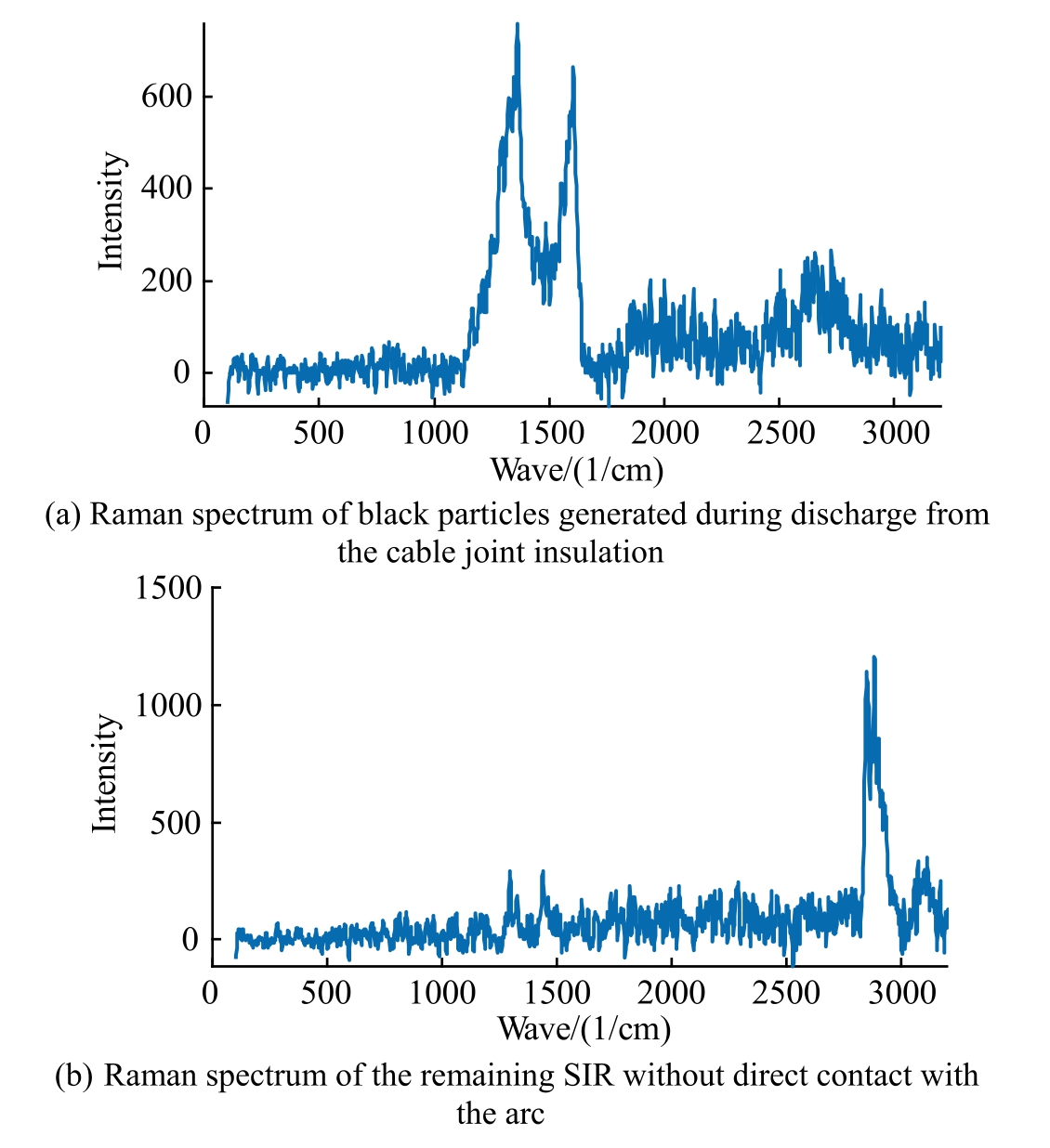
Fig.14.Raman spectrum analysis of different regions of the sample.
The black conductive material,primarily elemental carbon,generated during the reaction accumulates in the groove as particles of varying sizes [18].The largest particles can reach diameters of up to 300 μm,whereas the smallest particles are approximately 10 μm in diameter.These particles originate from the arc discharge process,during which high temperatures and polarizing electric fields cause molecular chain breakage in cross-linked polyethylene and silicone rubber.This leads to exchange reactions,oxidative cross-linking,and hydrolysis of silicon–oxygen bonds,producing various secondary products[19].
3 Scenario of sub-cycle incipient fault
The experimental observations reveal that incipient faults are single-phase ground discharges from the cable conductor to the grounding layer of the cable joint.During these faults,progressive insulation erosion combined with changes in the electrical characteristics causes incipient faults to evolve into permanent faults.Therefore,analyzing the developmental process of incipient faults is essential for accurately assessing their characteristics.
Fig.15(a) depicts a scenario in which no moisture is present within the pore,or external moisture has not yet reached the “pre-fault state” required to trigger an incipient fault.In this condition,the conductor remains exposed only to the open environment.For a cable joint without moisture infiltration,the effective insulation distance between the high-potential conductor and the grounding point is the sum of the cable insulation thickness and the joint insulation thickness.This distance exceeds the breakdown threshold for 10 kV cable accessories reported in existing studies [20,21],thereby prevent ing discharge.
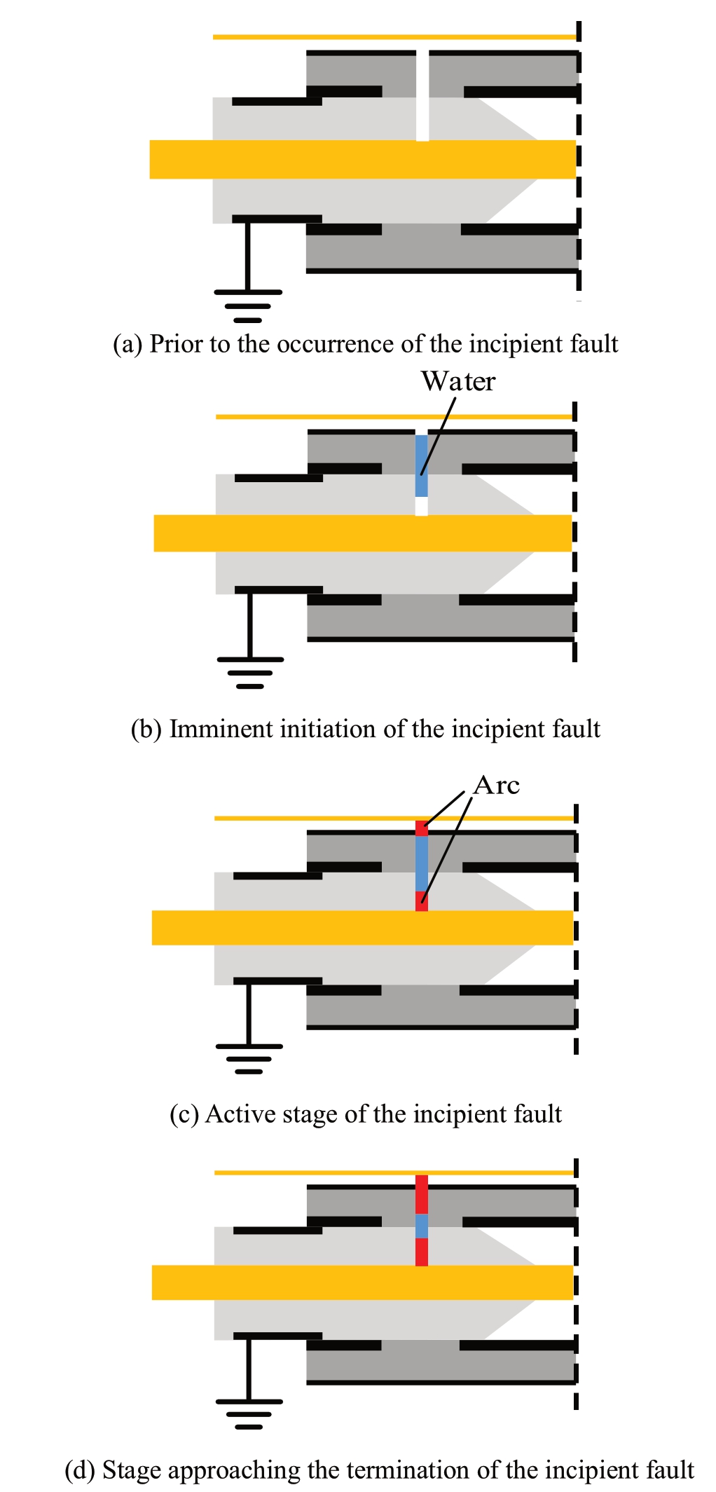
Fig.15.Development process of the sub-cycle incipient fault.
Under actual operating conditions,moisture can infiltrate the cable joint through the pore in the form of rainwater or condensation,forming droplets within the pore,as illustrated in Fig.15(b).These droplets create a localized conductive area,effectively shortening the insulating distance.The reduced insulation length increases the electric fie ld strength along the insulating surface between the high-potential conductor and the grounding wire.
When the electric field strength between the cable conductor and the grounding line exceeds the breakdown threshold,an incipient fault is triggered.Experimental results show that such faults often initiate during the rising phase of the absolute voltage amplitude,with a higher likelihood of occurrence as the voltage crosses the negative half-cycle.This behavior is linked to the near-cathode effect of the arc [22,23].During the incipient fault,white vapor is observed—produced by rapid water evaporation within the pore—which dissipates quickly,as shown in Fig.5(a).In contrast,smoke produced from arc erosion of the insulation can linger in the surrounding environment for a longer duration,consistent with findings in existing research.The primary components of the observed vapor are fine droplets produced by the rapid evaporation and subsequent condensation of water within the pores.Based on this,the incipient fault process can be inferred,as depicted in Fig.15(c).During the fault,the accumulated water within the pore separates the air into two regions—inside and outside the pore—while effectively extending the conductor.This configuration suggests that arcs are present at both ends of the accumulated water[24].The evaporation time of the accumulated water can be calculated as follows:
where l represents the length of the water column,and V is its volume.For simplicity,in this rough calculation,the water within the pore is approximated as a column with a uniform cross-sectional area.The area at the moment t is st.Consequently,Eq.(5) can be converted to Eq.(6):
where Vt denotes the water accumulation capacity,c is the specific heat capacity of water,and ρ represents the density of water.In a rough calculation,as the pore diameter of the insulation does not change significantly during the incipient fault process,the internal and external crosssectional areas can be assumed to remain constant and are equal to st.
The water capacity of a single pore in the experimental sample,from empty to completely filled,is estimated to range between 0 and several milliliters.Correspondingly,the heat required for complete evaporation ranges from 0 to several tens of joules.In a rough estimation,assuming that all the thermal energy generated by the arc is utilized to heat the water within the pore,the evaporation process would require only a few milliseconds when the effective current of the incipient fault is on the order of several amperes.This timescale closely aligns with the experimentally observed duration of incipient faults.Therefore,an incipient fault terminates when the water within the pore is completely evaporated.The corresponding process is shown in Fig.15(d).The sequence of events before and after the occurrence of an incipient fault can be summarized as follows: normal environment → accumulation of liquid water reduces the insulation path distance → incipient fault initiation → arc discharge causes evaporation of the liquid water →insulation path length increases →discharge vanishes →incipient fault terminates [25].Once the incipient fault ceases,the condition of the pore reverts to a state similar to that shown in Fig.15(a).
During an incipient fault,the high temperature of the arc burns the insulation,leaving conductive erosion marks on the insulation surface in direct contact with the arc.Although the duration of a single incipient fault is short,the damage caused by arc discharge is irreversible and accumulative.The formation of conductive material primarily composed of elemental carbon during insulation breakdown gradually increases,extending the conductive trace.This process deepens the erosion zone and enlarges the pore’s inner diameter,thereby increasing its waterholding capacity while simultaneously reducing the amount of water required to trigger subsequent incipient faults.Consequently,the cumulative damage from previous faults intensifies the severity of future faults.The presence of conductive erosion traces is reflected in a progressive decline in resistance values with each discharge event.This reduction in resistance leads to a gradual increase in fault current,ultimately accelerating the transition from incipient to permanent faults.
The fault scenario corresponding to the sub-cycle incipient fault in Fig.15 is modeled by the equivalent circuit shown in Fig.16.In this model,Ra and Ca represent the resistance and capacitance,respectively,of the insulation in the annular cross-sectional region that remains unaffected by the incipient fault.Rb and Cb represent the resistance and capacitance of the completely unaffected portion of the insulation.These two insulation sections are connected in parallel.Rw and Cw denote the resistance and capacit ance of the water accumulated in the cavity,respectively,whereas Rv and Cv represent the resistance and capacitance of the air within the pore,respectively.Based on this configuration,the expression for calculating the fault current If can be derived as follows:
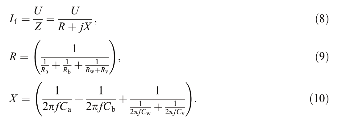
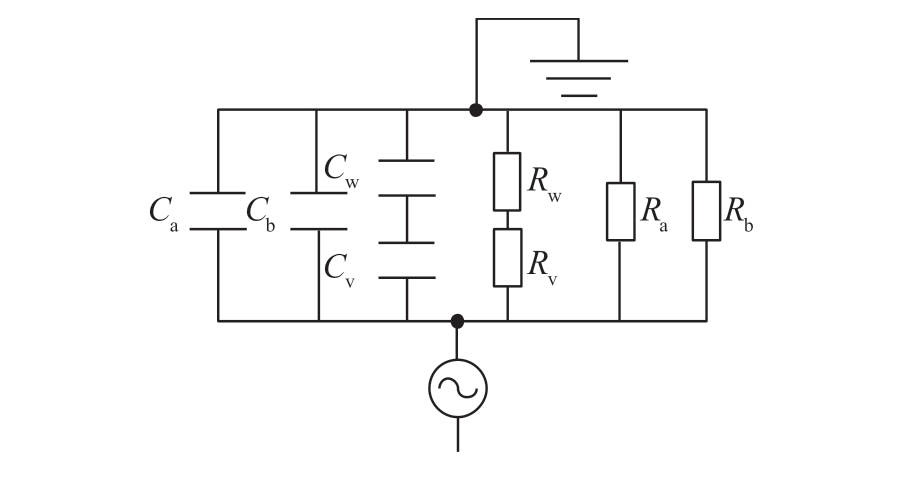
Fig.16.Fault circuit of the sub-cycle incipient fault.
4 Conclusion
This study analyzed the sub-cycle incipient fault phenomenon in cable joints caused by water ingress,focusing on the fault process and resistance characteristics during incipient faults.The main findings can be summarized as follows:
1) Incipient faults manifest as intermittent arc discharges between the grounding line and the highpotential cable conductor.Even in cases where cable joints are aged or externally damaged,a dry environment can still provide sufficient insulation strength to prevent breakdown.However,when liquid water infiltrates pores within the joint—owing to factors such as rainfall or con densation—it creates a conductive path that shortens the effective insulation distance.This reduction in insulation length increases the local electric field strength,thereby lowering the breakdown threshold.Once the electric field exceeds this threshold,arc discharge occurs.
2) Incipient faults typically appear as single-phase ground faults characterized by short discharge paths and low fault resistance.The fault current amplitude can range from several hundred to several thousand amperes.These faults are typically initiated on the rising edge of the voltage waveform,with a higher probability of occurrence during the negative halfcycle.The fault duration is slightly shorter than half a power-frequency cycle,typically around 0.002–0.005 s.The current waveform exhibits nonlinear characteristics,with a growth rate in the rising phase more than twice that of the corresponding voltage increase,followed by a decay rate exceeding that of the voltage drop.During incipient faults,visible arcing and water vapor emission occur between the pore and the grounding line.Once the discharge ceases,the pore returns to a dry state.The arc discharge produces cumulative and irreversible damage to the insulation surface,including enlargement of the pore’s inner diameter,decomposition of the silicone rubber insulation,and the formation of conductive traces along the pore walls.These changes progressively reduce the volume of water required to trigger subsequent incipient faults,thereby lowering the initiation threshold.The repetitive current variation process creates favorable conditions for applying artificial intelligence methods,such as probabilitybased waveform classification [1],total measurable fault information residual analysis [3],and other characteristic-based approaches to detection and identification of incipient faults.
3) With multiple incipient faults,the conductive paths expand and experience progressively more intense arc discharges.When an incipient fault can no longer self-extinguish without external intervention,it develops into a permanent fault.Permanent fault currents can reach several kilo-amperes,and the resulting arc rapidly erodes the insulation,enlarging pore diameters to the centimeter scale within seconds.Although permanent faults typically originate as single-phase ground faults,the severe damage caused during discharge can propagate to cable joints of other phases,potentially leading to twophase or three-phase grounding faults.
CRediT authorship contribution statement
Zhipeng Yu: Writing– original draft,Data curation,Formal analysis.Yongpeng Xu: Formal analysis,Conceptualization.Guoliang Qi: Resources.Wenwei Tan: Resources. Weiliang Guan: Resources. Xiuchen Jiang: Conceptualization,Methodology.
Declaration of competing interest
The authors declare the following financial interests/personal relationships which may be considered as potential competing interests: Guoliang Qi,Wenwei Tan,and Weiliang Guanare currently employed by China Southern Power Grid Guangdong Power Grid Co.,LTD.
Acknowledgments
This work was supported by National Natural Science Foundation of China (No.52077133).
Appendix A Supplementary material
Supplementary data to this article can be found online at https://doi.org/10.1016/j.gloei.2025.05.009.
References
[1]S.H.Xiong,Y.D.Liu,J.Fang,et al.,Incipient fault identification in power distribution systems via human-level concept learning,IEEE Trans.Smart Grid 11 (6) (2020) 5239–5248.
[2]C.Kim,T.Bialek,J.Awiylika,An initial investigation for locating self-clearing faults in distribution systems,IEEE Trans.Smart Grid 4 (2) (2013) 1105–1112.
[3]Y.K.Wu,Y.Su,Y.L.Wang,et al.,T-S fuzzy name="ref4" style="font-size: 1em; text-align: justify; text-indent: 2em; line-height: 1.8em; margin: 0.5em 0em;">[4]B.Kruizinga,P.A.A.F.Wouters,E.F.Steennis,Fault development upon water ingress in damaged low voltage underground power cables with polymer insulation,IEEE Trans.Dielectr.Electr.Insul.24 (2) (2017) 808–816.
[5]T.S.Sidhu,Z.H.Xu,Detection of incipient faults in distribution underground cables,IEEE Trans.Power Delivery 25 (3) (2010)1363–1371.
[6]C.K.Chang,C.S.Lai,R.N.Wu,Decision tree rules for insulation condition assessment of pre-molded power cable joints with artificial defects,IEEE Trans.Dielectr.Electr.Insul.26 (5) (2019)1636–1644.
[7]M.Amer,J.Laninga,W.McDermid,et al.,New experimental study on the DC flashover voltage of polymer insulators:combined effect of surface charges and air humidity,High Voltage 4 (4)(2019) 316–323.
[8]W.H.Zhang,Y.D.Jing,X.Y.Xiao,Model-based general arcing fault detection in medium-voltage distribution lines,IEEE Trans.Power Delivery 31 (5) (2016) 2231–2241.
[9]A.Ragusa,H.Sasse,A.P.Duffy,3D Model of partial discharge in defects with different sizes and positions in power cable for distribution and transmission networks,IET Sci.,Measur.Technol.14 (9) (2020) 776–783.
[10]C.Wang,G.Peng,R.Song,et al.,Research on high energy efficiency and low bit-width floating-point type data for abnormal object detection of transmission lines,Global Energy Interconnection 7 (3) (2024) 324–335.
[11]O.Maruyama,T.Nakano,T.Mimura,et al.,Fundamental study of ground fault accident in HTS cable [J],IEEE Trans.Appl.Supercond.27 (4) (2017) 1–5.
[12]T.Zhou,X.Zhu,H.Yang,et al.,Identification of XLPE cable insulation defects based on deep learning,Global Energy Interconnection 6 (1) (2023) 36–49.
[13]W.J.Xu,J.X.Niu,K.Y.Tian,et al.,Enhanced pollution flashover of a slurry coalescence superhydroph obic coating,IEEE Trans.Dielectr.Electr.Insul.28 (1) (2021) 310–317.
[14]J.M.Kong,K.Zhou,Y.D.Chen,et al.,A novel condition assessment method for corrugated aluminum sheathed XLPE cables based on evolved gas analysis,IEEE Trans.Dielectr.Electr.Insul.30 (2) (2023) 883–891.
[15]J.Li,Z.C.Guan,L.M.Wang,et al.,An experimental study of AC arc propagation over a contaminate d surface,IEEE Trans.Dielectr.Electr.Insul.19 (4) (2012) 1360–1368.
[16]M.Z.Rong,R.G.Ma,J.X.Chen,et al.,Numerical investigation on arc behavior in low-voltage arc chamber considering turbulence effect,IEEE Trans.Plasma Sci.42 (10) (2014) 2716–2717.
[17]D.K.Cai,A.Neyer,R.Kuckuk,et al.,Raman,mid-infrared,nearinfrared and ultraviolet–visible spectroscopy of PDMS silicone rubber for characterization of polymer optical waveguide materials,J.Mol.Struct.976 (1–3) (2010) 274–281.
[18]S.Kumagai,N.Yoshimura,Tracking and erosion of HTV silicone rubber and suppression mechanism of ATH,IEEE Trans.Dielectr.Electr.Insul.8 (2) (2001) 203–211.
[19]H.X.Cong,Q.M.Li,J.Y.Xing,et al.,Modeling study of the secondary arc with stochastic initial positions caused by the primary arc,IEEE Trans.Plasma Sci.43 (6) (2015) 2046–2053.
[20]K.Cheng,J.Craighead,S.Cress,Arc length vs.electrode gap for underground cable arc flash hazard analysis,in: Proceedings of 2017 IEEE IAS Electrical Safety Workshop (ESW),Reno,USA,2017,pp.1–5.
[21]“IEEE Standard for Insulation Shields on Medium-Voltage (15–35 kV) Cable Joints and Separable Connectors”,in: IEEE Std 592-2018 (Revision of IEEE Std 592-2007).Pp.1–21,29 June 2018.
[22]Z.X.Wang,Y.B.Tian,H.Ma,et al.,Decay modes of anode surface temperature after current zero in vacuum arcs: part II:theoretical study of dielectric recovery strength,IEEE Trans.Plasma Sci.43 (10) (2015) 3734–3743.
[23]T.P.Briels,J.Kos,G.J.Winands,et al.,Positive and negative streamers in ambient air: measuring diameter,velocity and dissipated energy,J.Phys.D Appl.Phys.41 (23) (2008) 234004.
[24]2001 annual report conference on electrical insulation and dielectric phenomena (cat.No.01CH37225).2001 Annual Report Conference on Electrical Insulation and Dielectric Phenomena.Kitchener,Canada.
[25]F.Aouabed,A.Bayadi,A.E.Rahmani,et al.,Finite element modelling of electric field and voltage distribution on a siliconeinsulating surface covered with water droplets,IEEE Trans.Dielectr.Electr.Insul.25 (2) (2018) 413–420.
Received 12 July 2024;revised 5 May 2025;accepted 26 May 2025
Peer review under the responsibility of Global Energy Interconnection Group Co.Ltd.
* Corresponding author.
E-mail addresses: yuzp_jd@sjtu.edu.cn (Z.Yu),xyp3525@sjtu.edu.cn(Y.Xu),373448264@qq.com (G.Qi),27927970@qq.com (W.Tan),106032245@qq.com (W.Guan),xcjiang@sjtu.edu.cn (X.Jiang).
https://doi.org/10.1016/j.gloei.2025.05.009
2096-5117/© 2025 Global Energy Interconnection Group Co.Ltd.Publishing services by Elsevier B.V.on behalf of KeAi Communications Co.Ltd.This is an open access article under the CC BY-NC-ND license(http://creativecommons.org/licenses/by-nc-nd/4.0/).

ZhipengYu received a B.S.degree from Shandong University,Shandong,China,in 2017,the M.S degree from Shanghai University of electric power,Shanghai,China in 2020,and he is now pursuing his Ph.D.at Shanghai Jiao Tong University,Shanghai,China.His interests include electrical measuring technology,diagnostics of incipient fault on cable and cable joint