
0 Introduction
Climate one of the main issues nowadays is the world’s excessive dependence on fossil fuels.Using electric cars will help to lower demand for fossil fuels and emissions of greenhouse gases.Electric vehicles running on renewable sources such as wind or solar power are another promising alternative to conventional ICEs with zero emissions.Globally,we are rising to the challenge of depending less on fossil fuels and combating climate change by implementing renewable energy sources [1,2].Fig.1 indicates that the electricity sector is a major source of greenhouse gas emissions,accounting for 38% of total emissions resulting from the use of fossil fuels such as coal and natural gas for electricity generation.The industry sector makes up 21% of the overall share of the total,mainly in the production of iron and steel,along with chemicals and cement.The building sector contributes around 10%,mainly it is on residential and commercial buildings.The transport sector also counts for 10%,with road transport constituting most parts and some share of emissions from Air travel.Last,agriculture and landfills account for 7% of emissions.Implementing cleaner technologies and improving energy efficiency will be crucial in reducing the environmental impact linked to natural gas and other fossil fuels [3].Dependable,user-friendly charging infrastructure will be essential as electric mobility expands.By 2030,around half of private and nearly all public transport is expected to be electric [4].Customer benefits of V2G technology include cost savings,energy indep endence,and a positive environmental impact [5].The technology saves its customers millions of dollars’ worth of electricity charges as they can charge their EV in off-peak hours.At the same time,the customers can feed back to the utility grid all surplus generated during peak consumption hours.In addition,utility and governm ent incentives for V2G participation reduce EV ownership costs.For the second aspect,V2G technology improves energy independence by allowing customers to store excess renewable energy in their EV batteries [6].The conventional grid is less needed.V2G reduces the need for public charging stations because most charging needs can be met at home [7].
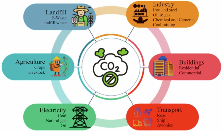
Fig.1.GHG emissions at various sectors.
Bidirectional converters with V2G technology are expected to be the future focus of off-board EV chargers and are likely to play a cru cial role in making EVs act as distributed energy resources that support the grid in various ways[8].V2G can provide instantaneous power during grid instabilities caused by renewable energy intermittency.Additionally,bidirectional chargers equipped with proper control algorithms can enhance overall grid power quality by actively eliminating harmonics injected by other local nonlinear loads [9].This also allows electric vehicles to play a dual role,that is,besides being a mode of transport,also as an important resource for the grid that supports an even more stable and efficient energy system.The latest findings of different types of controllers for the bidirectional converters make quite a number of linear control strategies proposed for controlling the chargers of EVs.Many conventional PID controllers that may not prove to be the best ones in managing nonlinear characteristics.FLCs rely heavily on expert knowledge to design membership functions and rules,which can be subjective and time-consuming.However,FLCs assume an accurate system model or sufficient information,which usu ally can be difficult to obtain practically [10].Other methods,such as GA-optimising controllers,are presented [11].However,the applicability of these methods may be narrower than others because there appears to be no real proof from the real world besides scale test ing in complex and intricate grid environments.Additionally,the Super Twisting Sliding Mode Controller mentioned in [12]is strong against disturbances but requires more research to fix issues like chattering,which can create noise and reduce power conversion efficiency.In[13],they introduce the MPC strategy for G2V and V2G modes,enhancing power flow management.However,the approach might cause distortion in the current since the selected and target voltage vectors are not the same.A variety of optimisation methods have been employ ed by V2G systems to address these issues.Particle Swarm Optimisation (PSO) enhances performance in a diverse array of grid conditions,despite the potential for instability and extended settling times [14].Despite its slower convergence rate,the Whale Optimisation Algorithm (WOA) is more effective in addressing multiobjective problems such as reactive power and voltage regulation [15].Even though they necessitate a significant amount of computing power,other well-known optimisation methods,such as Ant Colony Optimi sation (ACO),are capable of identifying the most optimal routes and schedules [16].Simulated annealing (SA) is adaptable and effective in circumventing local optima,despite the fact that convergence may require a significant amount of time [17].The Firefly Algorithm (FA) is highly effective in the exploration of the solution space and the resolution of multimodal problems,despite the fact that it necessitates a significant amount of computing power [18].The complexity of these systems can make it difficult to comprehend the decision-making process,which can have an impact on optimisation and problem-solving.Additionally,the training of these systems for real-time use requires a significant amount of computing power.Studies have also demonstrated that the performance of a Deep Learning (DL) model is contingent upon the quantity and quality of its training.This is due to the fact that the training process requires a significant amount of computing power[19].
The literature review shows that ANFIS controllers are ideal for non-linear systems and robust to disturbances like V2G.ANFIS algorithms are ideal for real-time applications because they self-learn to adapt to different operating conditions and better performance than other optimisation algorithms [20].ANFIS controllers manage bidirectional energy flow,optimise energy efficiency,and stabilise grids.This makes ANFIS ideal for V2G controller online tuning [21,22].Despite being a mature technique,ANFIS remains highly effective for real-time nonlinear control and is further enhanced in this work through adaptive weight optimisation.This work makes the foll owing significant contributions:
 By using BPN techniques with linear weight updates,a new integrated control method is proposed to enable the controller to efficiently manage the power exchan ge between EVs and the grid and provide stable regulation of the DC-link voltage inside the V2G system.
 This method helps the controller to pick up knowledge and adapt faster.Moreover,SRF control stra tegies help to improve the stability and accuracy of the converter.
 MATLAB simulation results show improved power conversion quality by greatly reduce THD,preserving a stable DC link voltage,and so reducing performance error indices.
 To verify the dependability and practical relevance of the mo del,an experimental prototype was built.
These contributions address key challenges in real-time V2G control and set the foundation for future development of smart,adaptive EV-grid interfaces.
The rest of the paper is divided into the following parts: Section 1 describes the core components of V2G systems.Section 1.1 details the AC-DC converter with SRF controller,and Section 1.2 further explains the DC bus voltage and DC-DC converter control logic.Section 2 is comprised of the proposed design of a V2G/G2V installation including ANFIS implementation.For the implementations of the above-mentioned ANFIS,Section 2.1 is dedicated.The results of the simulations are reported in Section 3.A detailed analysis of the experimental data is given in Section 4.Section 5 of the chapter concludes with a summary of the important findings of the research.
1 Core components of the system design
The schematic version of the bidirectional EV charger system is presented in Fig.2.Six IGBTs with antiparallel diodes grouped in a three-phase two level arrangement make up the converter.Furthermore,the converter includes an LC filter to reduce the harmonic distortion of the current and AC voltage,as well as a DC link capacitor to smooth out the DC voltage [23,24].During the AC-DC,DC-DC conversion process,it makes use of sophisticated control algorithms such as the ANFIS and the PI controller to manage power flow and maintain a steady DC link voltage.When the pulse to the IGBT switches is interrupted,the converter transforms into a diode bridge rectifier,allowing the VSC to function in rectifier mode.This merely transmits a three-phase AC voltage into a DC voltage.This choice is essential when utilising grid power to charge an EVs battery (G2V).For V2G operation,the converter switches to inverter mode,allowing the EV battery to supply power back to the grid[25].The DC-DC converter’s configuration is consists of two MOSFET switches that are always driven by complementary control signals [26].The ANFIS controller changes the converter’s duty cycle in response to changes in input and output voltage and current.
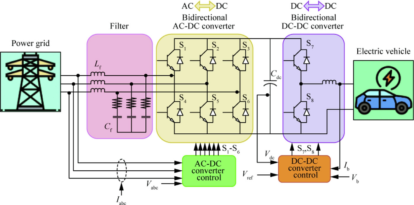
Fig.2.Schematic representation of V2G system.
1.1 Synchronous reference frame (SRF) controller
The SRF controller is exclusively employed during inverter mode,where power is injected from the battery into the grid [27,28].The SRF control structure for the proposed system is illustrated in Fig.3.In conjunction with PI and ANFIS controllers,the SRF transformation plays a vital role in bidirectional converters,ensuring stability,enhancing performance,and guaranteeing reliable operation of EVs within the smart grid ecosystem [29].The SRF controller runs by transforming the three-phase AC signals into a rotating reference frame (d-q frame),which simplifies the control of AC quantities by converting them into DC quantities.In V2G applications,the absence of a synchronised reference frame would result in mistaken power flow regulation,problems with power quality,a delayed reaction time,higher energy losses,and instability in the grid.
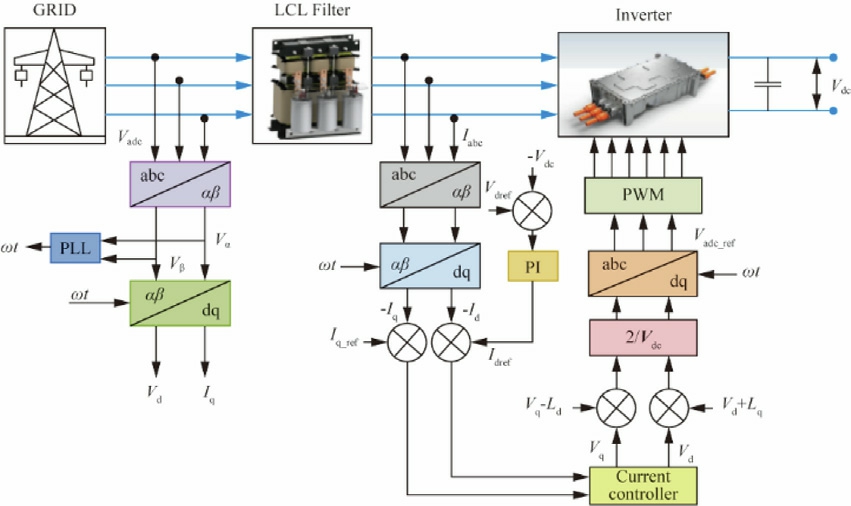
Fig.3.SRF Control for AC/DC Converter.
The grid side voltages and currents must be in phase for the transfer of active power to the load.PLL will generate a reference signal,which must be in phase with the actual voltage to communicate this current.PLL generates a signal 90° out of phase with the true voltage to give reactive power to the load.Therefore,in a grid-connected system,PLL is used to create reference signals,which are then utilised as a guide for implementing the current controller[30].To provide effective power flow regulation,and system stability between the EV and the grid,PLLs continually detect,compute,and modify the phase error.
In this closed-loop technique,PLL generates the angle ωt and the abccoordinates are changed to dq coordinates using the SRF transformation to obtain the two current components,Id and Iq [31].

where α and β are the direct and quadrature axes of the stationary reference frame respectively.Maintaining a constant DC link voltage (Vdc)is crucial for stable operation.To regulate the DC output voltage,the PI controller receives the error signal generated by comparing the actual DC voltage (Vdc)to the reference value (800 V).The control equation for the DC link voltage can be represented as
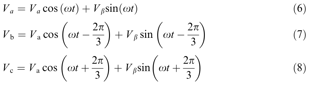
The d component of the input current (Id) is compared to the output of the PI controller,which serves as the Id current reference.To maintain the unity power factor,the q component of the input current (Iq)is set to zero.The output of each PI current controller is scaled and sent to the PWM scheme,and the errors derived from each current component are fed to the corresponding controller.Va,Vb,and Vc are obtained by inversely transforming Park’s transformation.
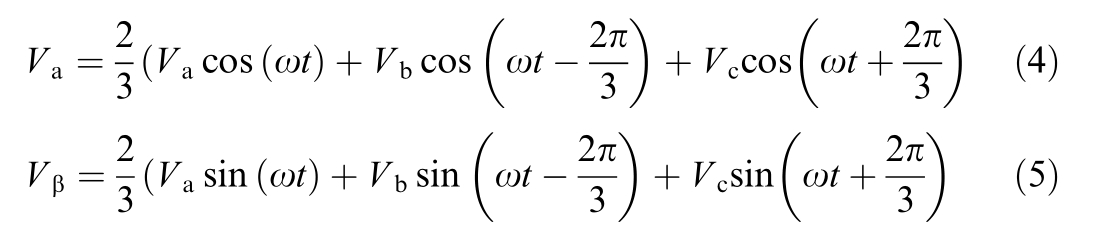
From the above Eqs.(4) and (5) Va,Vb and Vc are calculated.
The d-axis and q-axis currents Id,Iq are controlled using PI controllers.The co ntrol equations for the PI controllers are:
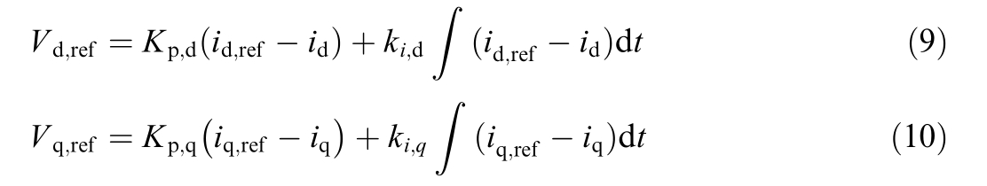
where:
The reference voltages for the d and q axes are Vdref and Vqref,respectively,while the reference currents for the d and q axes are idref and iqref.The proportional and integral gains of the d-axis PI controller are Kpd and kid,while those of the q-axis PI controller are Kpq and kiq.The PLL is furnished with the function of synchronizing the converter with the grid.The PLL tracks the grid phase angle (θ).
1.2 DC bus voltage and dc-dc converter control
Fig.4 displays the DC bus voltage control along with bidirectional DC/DC converter’s control diagram using ANFIS controller.The ANFIS controller ensures the reference value for DC bus voltage,and it maintains for both modes of operation.It regulates the pulse by measuring the battery’s current.The controller calculates the DC power (Pbatref)exchanged by the battery from DC bus voltage (Ubatref)and power demand (PD).This bidirectional DC-DC converter control provides faster response of detecting any variation of load on either side at the sampling frequency of 10 kHz.This converter also ensures the low THD and power factor at unity.This converter also works in CC mode and controls the battery current to have a reference battery current value,Ibref.Finally,this reference battery current is controlled by the ANFIS controller and expressed as follows:
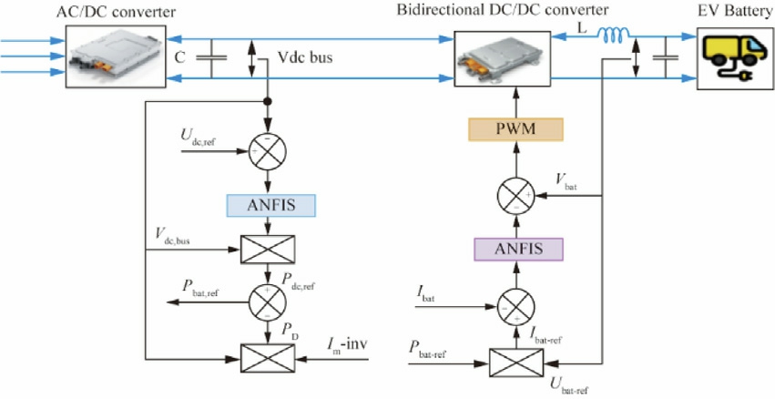
Fig.4.Control Block Diagram of DC/DC Converter.
where Umbat is the modulated voltage of DC/DC converter,Vbat is battery terminal voltage (V),and Ibat is the battery current.
1.3 System control with mode switching
i) Charging Mode(G 2V):
The bidirectional DC/DC converter modulates the DC link voltage in the cha rging mode to correspond with the battery voltage.Fig.5 represents the switching mode operation between the G2V and V2G.First,it determines whether the battery voltage ![]() is higher than the maximum threshold (Vbatmax)or lower than the minimum threshold (Vbatmin).The system switches to Constant Current (CC) mode if the battery voltage falls outside of these ranges.In CC mode,the duty cycle (Dbuck)of the buck converter is set to keep the battery current (Ibat)constant until the battery voltage (Vbatmin or Vbatmax)reaches the target level.The system switches to Constant Voltage (CV) mode if the battery voltage is within the allowable range.When in CV mode,the duty cycle (Dboo st)of the boost converter is set to keep the battery voltage (Vbat)constant until the battery current equals the reference current (Ibatref).This guarantees safe and effective grid charging of the battery.
is higher than the maximum threshold (Vbatmax)or lower than the minimum threshold (Vbatmin).The system switches to Constant Current (CC) mode if the battery voltage falls outside of these ranges.In CC mode,the duty cycle (Dbuck)of the buck converter is set to keep the battery current (Ibat)constant until the battery voltage (Vbatmin or Vbatmax)reaches the target level.The system switches to Constant Voltage (CV) mode if the battery voltage is within the allowable range.When in CV mode,the duty cycle (Dboo st)of the boost converter is set to keep the battery voltage (Vbat)constant until the battery current equals the reference current (Ibatref).This guarantees safe and effective grid charging of the battery.
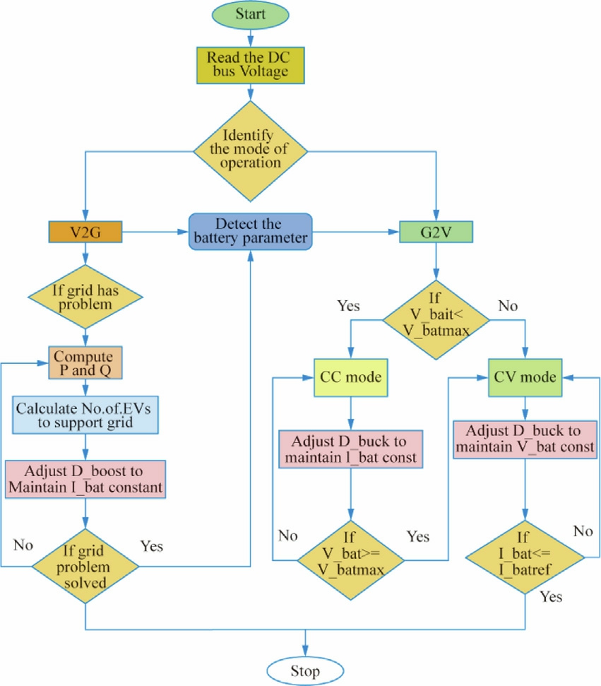
Fig.5.System switching mode operation.
ii) Discharging Mode (V2G):
The system’s primary goal in the V2G mode is to return energy from the EV battery to the grid.Finding any problems with the battery parameters is the first step in the procedure.The system determines the active (P) and reactive(Q) power needed to support the grid in the event that an issue is found.After that,it calculates how many EVs are required to supply this assistance.To keep the battery current(Ibat)constant,the dutycycle(Dboost)of the boost converter is changed.The gridis continuously monitored by the system to see if the issue has been fixed.The procedure is over if the grid problem is fixed.If not,the system keeps modifying Dboost to guarantee a steady and effective energy transfer from the car to the grid until the grid issue is resolved.The output voltage during boost mode may be represented as Eq.(13).

2 Design of the proposed V2G installation
The suggested V2G installation can be integrated into different kinds of electric vehicles and grid configurations because of its scalable and flexible design.To guarantee optimum performance and dependability,the V2G inst allation design incorporates a number of crucial elements and factors.The experimental and simulation parameters for the entire system are displayed in Table 1.To achieve the necessary performance in terms of DC link voltage,rated power,and efficiency,these parameters were computed in advance.
Table 1 The specifications of the complete system.
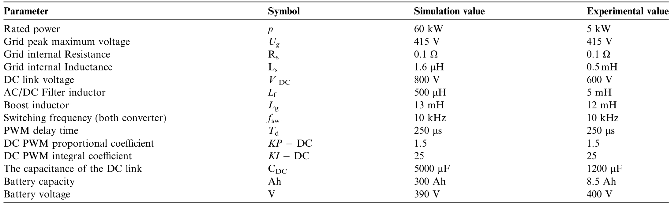
Table 2 The load pattern used in the simulation.
2.1 ANFIS implementation
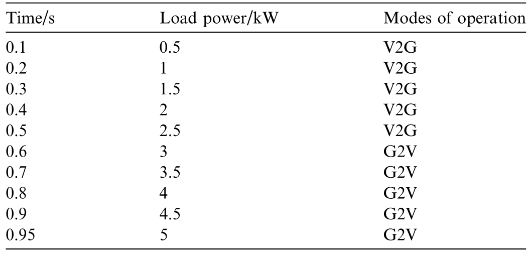
The ANFIS model,a powerful tool for adaptive nonlinear systems,was employed to enhance the control performance of a three-phase bidirectional converter in a V2G system.The ANFIS uses a five-layer neural network structure to emulate a Takagi-Sugeno fuzzy inference system,with each layer corresponding to a specific step in the fuzzy inference process.For this explanation,we will assume a simplified scenario with two inputs to the fuzzy system,denoted as x and y,and a single output represented by z as shown in Fig.6 [32,33].
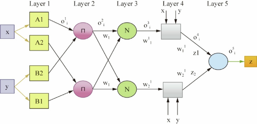
Fig.6.Typical structure of ANFIS controller.
The first layer of the ANFIS network is responsible for fuzzifying the input values,x and y in our example.Each neuron in this layer represents a linguistic variable,essentially a fuzzy label for a specific range of input values.These neurons perform the fuzzification process by applying membership functions to the inputs.Membership functions define the degree to which an input value belongs to a particular fuzzy set.Common membership function shapes include triangular,trapezoidal,and Gaussian.
The “ ci ” denotes the center,and “a i” represents the width of the membership function.These parameters are commonly refer red to as “premises”.The outputs of the first layer are as follows:
The term ![]() represents the degree to which the value x belongs to the set Ai.The second layer of the ANFIS network calculates a single output value for each rule by combining membership degrees from layer 1.This product represents the rule’s “firing strength,” indicating its influence on the final output.These rule weights are crucial for determining the overall contribution of each rule to the final ANFIS output.
represents the degree to which the value x belongs to the set Ai.The second layer of the ANFIS network calculates a single output value for each rule by combining membership degrees from layer 1.This product represents the rule’s “firing strength,” indicating its influence on the final output.These rule weights are crucial for determining the overall contribution of each rule to the final ANFIS output.

The third layer standardises the findings generated by the preceding layer.The acquired findings indicate the level of contribution of the value to the outcome.
The fourth layer is connected to the original inputs.The outcome is determined by evaluating a mathematical function that incorporates the input values and a linear combination of the starting inputs,following the Takagi-Sugeno technique.This is the step of defuzzification.
The output layer has a single neuron that computes the aggrega te of the signals received from the preceding layer.

This work proposes a style="vertical-align: middle; text-align: center;">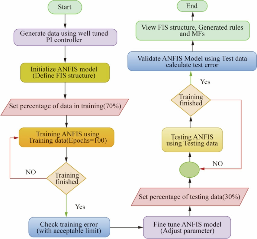
Fig.7.Flow chart for PI-tuned ANFIS controller.
The proposed ANFIS model,characterized by 44 nodes and a total of 50 parameters (20 linear and 30 nonlinear),was trained on a substantial dataset of 2,471,836 training data pairs.This training dataset was a 70% split from the original dataset of 3,531,194 data points,ensuring a robust learning process.The remaining 30%,or 1,059,358 data points,were reserved for rigorous testing to evaluate the model’s generalization capabilities.Fig.8 depicts the process of training the ANFIS.The initial training epochs demonstrated a steady decrease in the error metric,starting at 0.3342 and gradually converging to 0.3182 after reaching the 100th epoch.To expedite the training process,the step size was strategically increased to 0.015 after every 5th epoch.This adjustment allowed for larger parameter updates,potentially accelerating convergence.The developed ANFIS structure is shown in Fig.9.
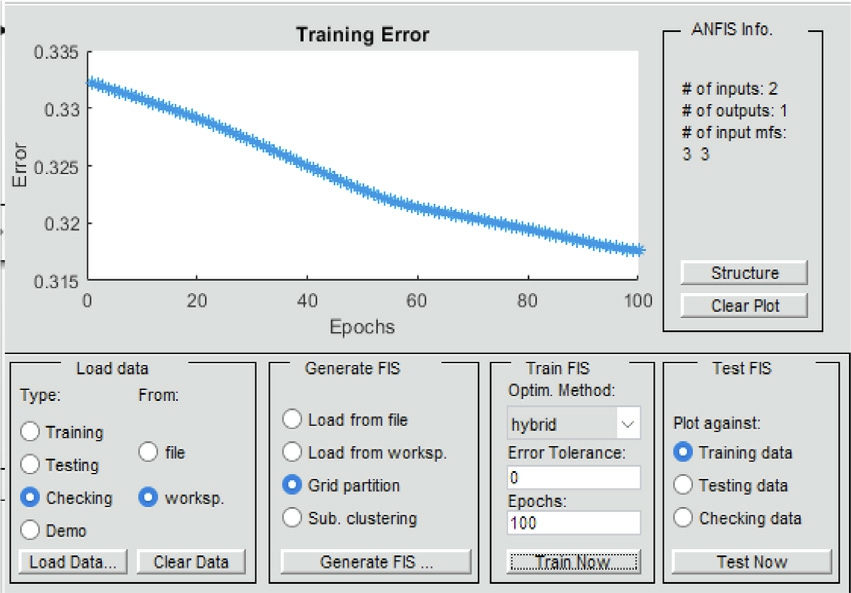
Fig.8.ANFIS training process.
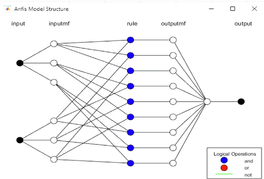
Fig.9.Developed ANFIS structure model.
To facilitate real-time implementation,the trained ANFIS model was translated into C/C++code using MATLAB’s Code Generation Tools.This code was subsequently integrated into the target hardware platform.In real-time operation,the model continuously receives input data from sensors,processes it through the ANFIS inference engine,and generates appropriate control signals for the power electronics converters.A robust feedback control loop ensures the system’s stability and desired performance.To maintain optimal performance and adaptability,ongoing monitoring and refinement of the ANFIS model are essential.
3 Simulation results and discussion
The system employs an LC filter to connect a threephase AC/DC converter to a 415 V,50 Hz grid supply.MATLAB is used to simulate a 60 kW EV charger with an external local load that has variable reactive power and a fixed active power of 5 kW.The proposed system uses a Li-ion battery pack with a nominal voltage of 390 V,which is typical for EV applications where battery pack voltages range between 180 V and 400 V.The state of charge (SoC) is initially set at 60%,meaning the battery volta ge will vary as it charges or discharges.The DC link voltage,which typically ranges from 400 V to 800 V,is set at 800 V for this three-phase system.To evaluate the controller’s performance,a three-mode simulation scenario was created.Modes 1 and 2 focus on battery charging G2V and discharging V2G,respectively.Mode 3 examines the dynamic behavior of the charger under variable load conditions.Fig.10 shows the transition from V2G to G2V mode using a PI controller,where voltage and current shift from being out phase to in phase,indicating power flow changes.Fig.11 shows how to switch from V2G to G2V mode using an ANFIS controller.Both the grid’s stability and power quality standards greatly affect the current levels in the V2G and G2V modes,respectively.To maintain grid stability and equalise other loads,current levels in V2G mode are usually substantially higher,approaching 50 A.Since the vehicle’s battery charging uses less power in G2V mode,the current levels are substantially lower,usually around 20 A.Fig.12 shows the grid voltage and current maintained by an ANFIS controller under variable load conditions during the transition from V2G to G2V mode.This demonstrates how well the controller handles dynamic variations in load.
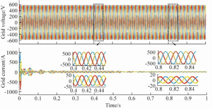
Fig.10.Grid Voltage and Current during V2G mode to G2V with the use of a pi controller.
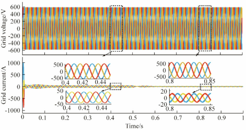
Fig.11.Grid Voltage and Current during V2G mode to G2V with the use of an ANFIS controller.
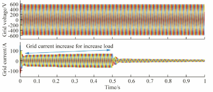
Fig.12.Grid Voltage and Current at variable load condition during V2G to G2Vmode transition with the use of an ANFIS controller.
This Table2 illustrates the load pattern applied in mode 3 operation.The system begins from V2G mode;gradually,the load power increases from 0.5 kW to 2.5 kW.On reaching 0.5 s,the mode shifted to G2V.Here,the load power increases from 3.0 kW to 5.0 kW.This setup will enable all-around assessment of the performance of the controller under charging and discharging conditions as well as under dynamic load conditions.The incrementing load influences the availability of power for charging of the battery.
Both the actual and reactive power levels,as measured by the PI and ANFI S controllers during the mode transition,are shown in Figs.13 and 14,respectively.The real power fluctuates slightly for each load change during V2G and G2V with an ANFIS controller,as shown in Fig.15.In G2V mode,the grid supplies active power to charge the vehicle’s battery,with a real power (P) value of approximately 60 kW and a reactive power (Q) value of around 5 kVAR.In V2G mode,the vehicle supplies active power back to the grid,with a real power (P) value of approximately 60 kW and a reactive power (Q) value of around 6.5 kVAR.The grid’s impedance is typically inductive,which means it consumes reactive power.When the EV supplies energy to the grid,it must also supply the reactive power required by the grid’s inductive impedance.This results in a higher reactive power output from the EV during V2G mode compared to G2V mode.Negative real power in V2G mode demonstrates the flow of power from electric vehicles to the grid.The G2V mode shows positive active power,indicating power is being transferred from the grid to the EVs.This transition shows that the controller tracks the reference P and Q instructions with effi-ciency.The controller’s steady-state and transient performance are investigated while changing the reactive power during the transition from discharging (mode 1)to charging (mode 2).Reactive power adjustment enhances the quality of grid current but may distort charger current.It is evident from this switchover that the ANFIS’s dynamic reaction outperforms that of the PI controller.For both Id and Iq,the ANFIS settles faster than the PI controller.
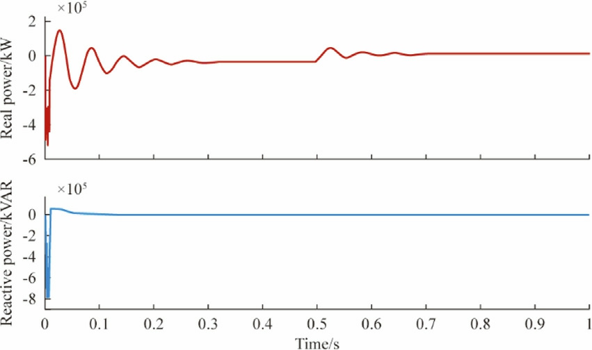
Fig.13.Real and Reactive power during V2G to G2V modes with PI controller.
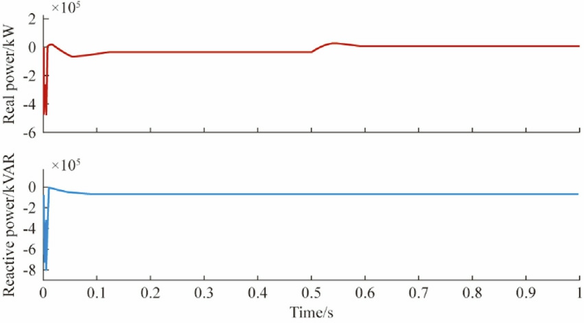
Fig.14.Real and Reactive power during V2G to G2V modes with ANFIS controller.
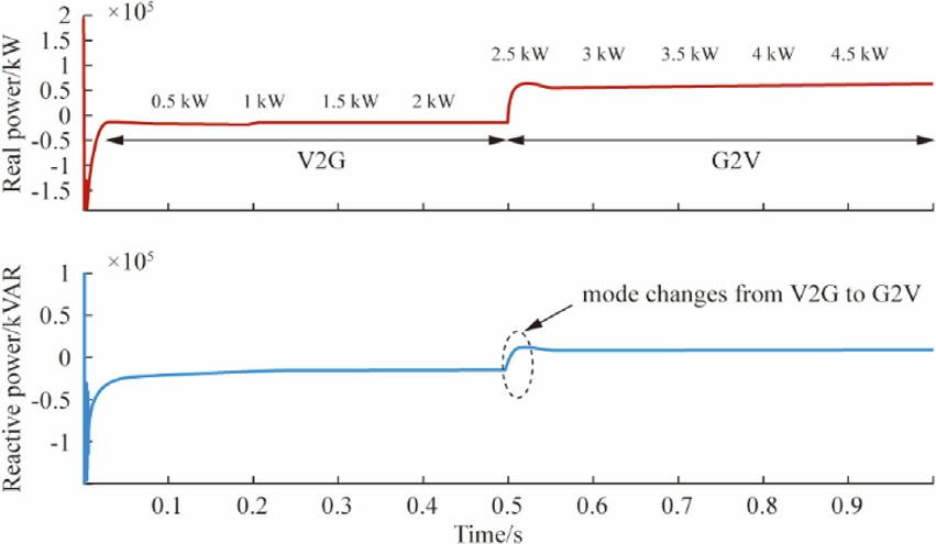
Fig.15.Real and Reactive power during V2G to G2V at variable load with ANFIS controller.
As seen in Figs.16 and 17,the DC bus voltage rises to a peak value in the V2G mode of operation before regulating at 800 V.To maintain a constant DC voltage,the AC grid voltage is converted to a high DC voltage of about 800 V across a DC link capacitor.
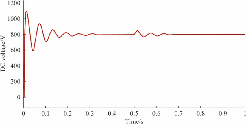
Fig.16.DC bus voltage during V2G to G2V mode with PI controller.
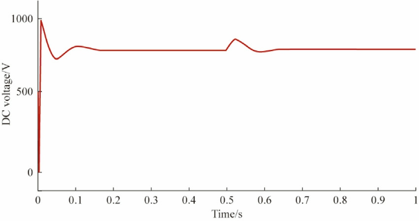
Fig.17.DC bus voltage during V2G to G2V mode with ANFIS controller.
Fig.18 shows that the ANFIS controller responds very well to fluctuating load conditions.The DC bus voltage remains stable during changes in the demand for load.Its adaptive nature makes it react very fast to changes in the demand for load,which helps in minimizing disturbances in voltage.This response is much faster than that of the traditional PI controllers,which have a tendency to be more unstable and have longer transient times.The ANFIS controller adjusts its charging parameters to ensure a stable DC bus voltage even under time-varying load conditions.From Figs.19 and 20,it is evident that SOC depends on the active power command.The SOC increases from 60% at the initial time up to 0.5 s during charging of the battery and then decreases step-by-step from 0.5 s to 1 s as the charger feeds energy into the system.Meanwhile,the battery current is switched from
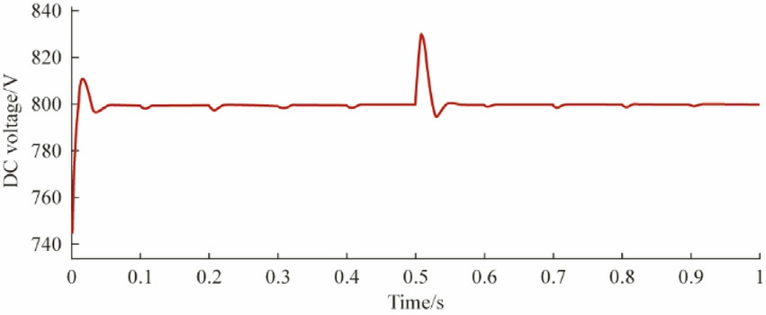
Fig.18.DC bus voltage at dynamic load during V2G to G2V mode with ANFIS controller.
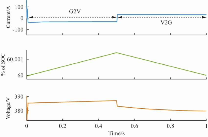
Fig.19.Voltage,current,and SOC of EV during G2V to V2G with PI control.
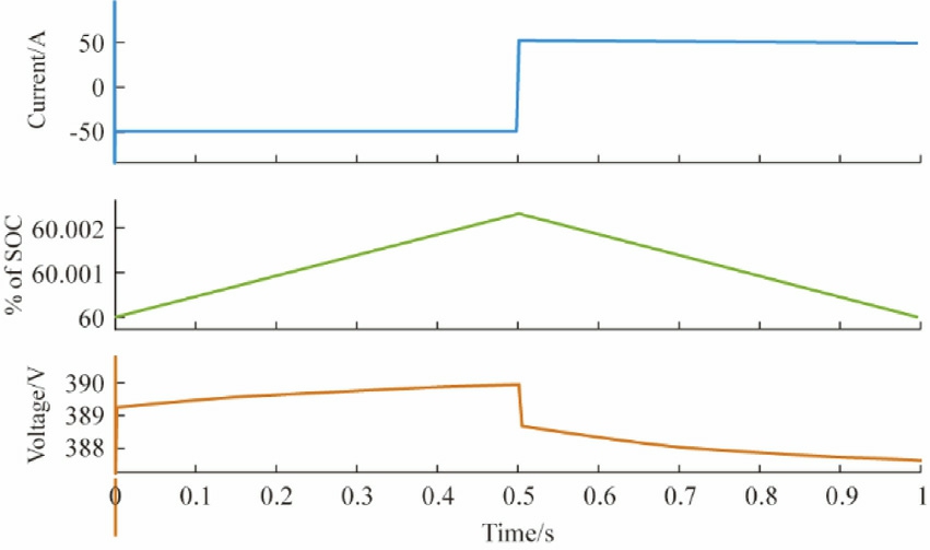
Fig.20.Voltage,current,and SOC of EV during G2V to V2G with ANFIS control.
50 A to 50 A during the charging mode to discharging mode,respectively.When charging,the battery voltage rises somewhat (by around 0.5 to 1 V) and slightly falls when it discharges.
The battery energy storage system always balances the load power as the load current fluctuates,as shown in Fig.21.With real changes in the load on the distribution system,the proposed ANFIS controller got rid of the uneven power changes.Load power rises 0.5 kW every 0.1 s to almost 4500 W in 0.5 s.EV battery power is released to support the rising load in V2G mode.Grid power may rise to charge the battery and meet growing load demand.After transition,load power rises to almost 8000 W in one second.In G2V mode,the grid supports local loads and charges the EV battery from both sides.As the battery charges,the system’s adaptive response to changing load conditions reduces battery power.
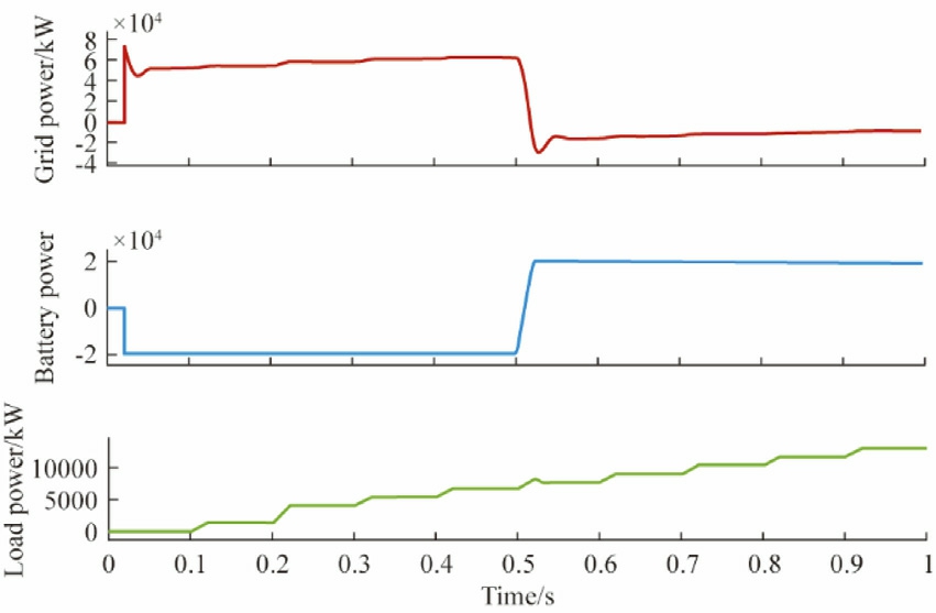
Fig.21.Dynamic response of grid power,load power,and battery power.
The THD analysis shows that PI controllers and ANFIS controllers differ significantly in their ability to reduce current harmonics in G2V and V2G modes.The THD of 3.27% for the ANFIS controller is shown in Fig.23,which is substantially less than the 6.96% THD for the PI controller (Fig.22).This suggests that when charging in G2V mode,the ANFIS controller is more successful at preserving a steady current.Similarly,the ANFIS controller outperforms the PI controller in V2G mode,with a THD of 3.36% (Fig.25) compared to 7.68%(Fig.24).This is true even though there is more distortion when power is fed back into the grid.Conversely,the THD values stay within acceptable bounds,demonstrating the presence of effective harmonic limitation and reasonably efficient operation.All things considered,the ANFIS controller continuously improves performance in terms of lowering THD,guaranteeing high power quality in both G2V and V2G modes.
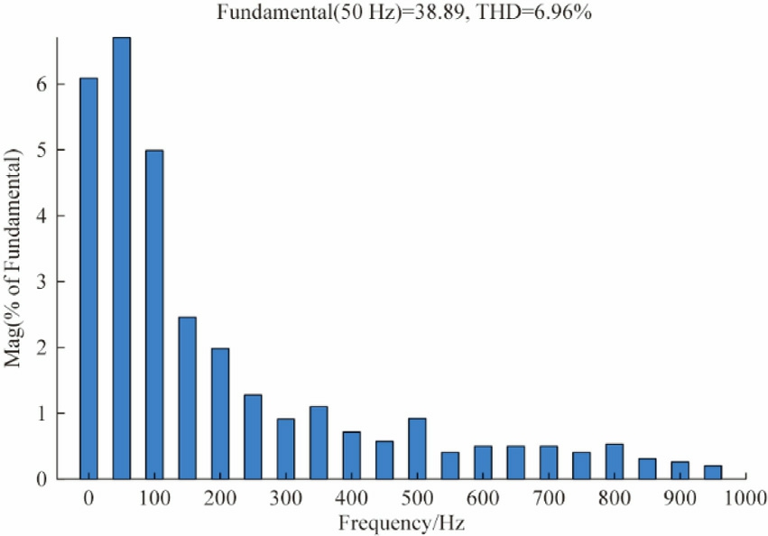
Fig.22.THD analysis of grid current during G2V mode using PI controller.
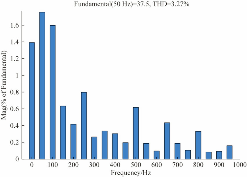
Fig.23.THD analysis of grid current during G2V mode using ANFIS controller.
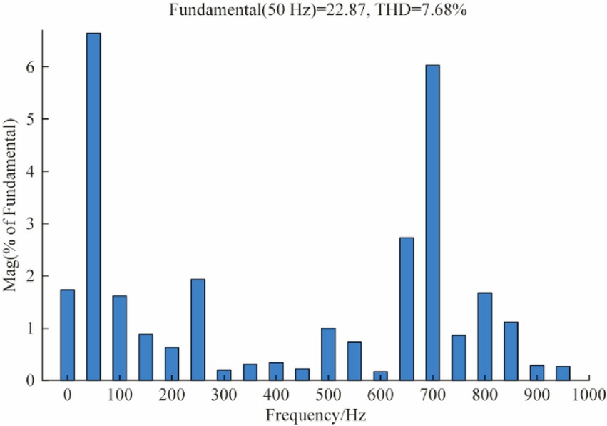
Fig.24.THD analysis of grid current during V2G mode using PI controller.
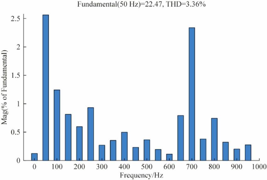
Fig.25.THD analysis of grid current during V2G mode using ANFIS controller.
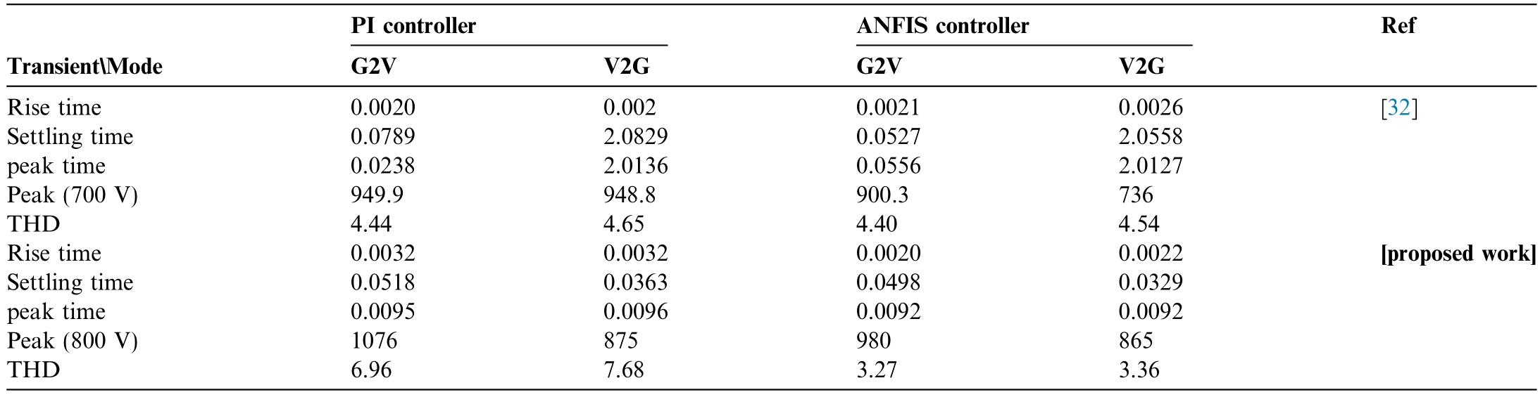
The Table 3 compares the performance of PI and ANFIS controllers under different transient conditions for both referenced and proposed works.The proposed work shows significant improvements in key performance metrics.These results highlight the effectiveness of the ANFIS controller in optimising V2G system performance under various load conditions,ensuring stable and efficient operation.
Table 3 Comparison of controller performance.
4 Experiment result
Fig.26 depicts the detailed hardware prototype developed in the lab for real-time evaluation of controller performance.The main platform is a three phase two level AC-DC converter,based on an IGBT with a subsequent bidirectional DC-DC converter.A programmable DC power supply,specifically the Chroma 62050 H-600 S,connected to the DC-DC converter,with an output of 5 kW and a rated voltage and current of 600 V and 8.5 A,it can mimic the dynamic characteristics of a battery,including charging a nd discharging cycles,state-of-charge variations.This enables the testing of the bidirectional converter’s performance under various battery conditions,ensuring robust and efficient operation in real-world scenarios.The grid side has three-line inductors with an inductance value of 5 mH and there is a DC link capacitor of 2200 μF.For hardware implementation,FPGA-based control system is the brains behind the bidirectional converter’s operation.Key algorithms,including PI and ANFIS controllers and Phase-Locked Loop (PLL),are implemented on a Spartan-6 LX9 FPGA.Vivado-2023.2 is a software tool used implementing digital circuits on Xilinx FPGAs.The PI and ANFIS controllers are responsible for regulating both voltage and current,ensuring that the DC link voltage is maintained at a stable 800 V.
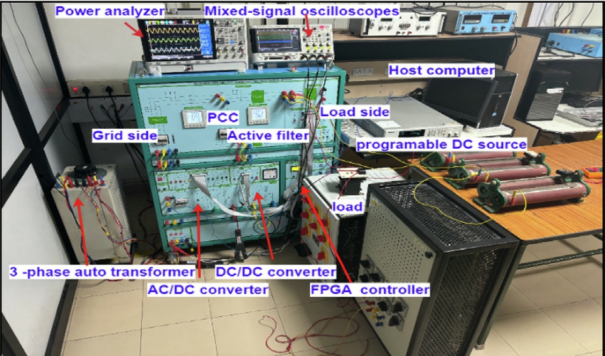
Fig.26.Hardware setup of the proposed system.
The PCC voltage and current waveforms during G2V operation are displayed in Fig.27,and during V2G operation,they are shown in Fig.28.The PCC voltage waveform is seen to stay roughly sinusoidal while exhibiting minor distortions during active power transfer.The main cause of these distortions is the introduction of harmonic currents by nonlinear loads.Small voltage fluctuations take place at the PCC as a result of the interaction between these harmonic currents and the grid impedance.The measured voltage Total Harmonic Distortion (THD) stays below 5% in spite of this effect,guaranteeing adherence to IEEE 519 standards.Additionally,the PCC current waveform exhibits good quality,and the current THD values fall within acceptable bounds.These findings validate that the suggested control strategy is effective in preserving a satisfactory level of power quality during both G2V and V2G operations.
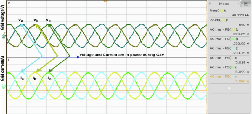
Fig.27.Voltage and current waveforms in G2V mode.
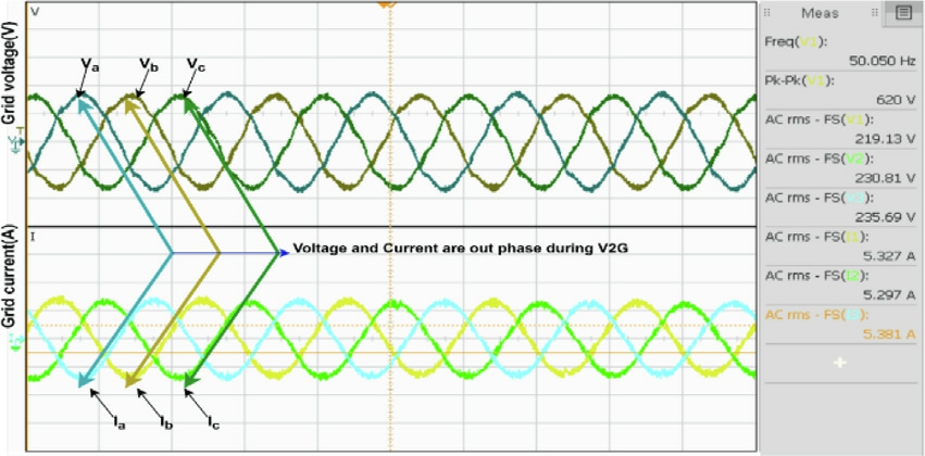
Fig.28.Voltage and current waveforms in V2G mode.
The EV charger serves as an active power filter,regulating reactive power and enhancing the quality of power,as illustrated in Fig.29.Distortion in the load current is induced by nonlinear loads prior to activation.The charger is prompted to supply the harmonic component of the load current by the activation,which results in a sinusoidal grid current.This capability emphasises the adaptability of V2G technology in the management of energy flow,as well as the improvement of grid stability and power quality.
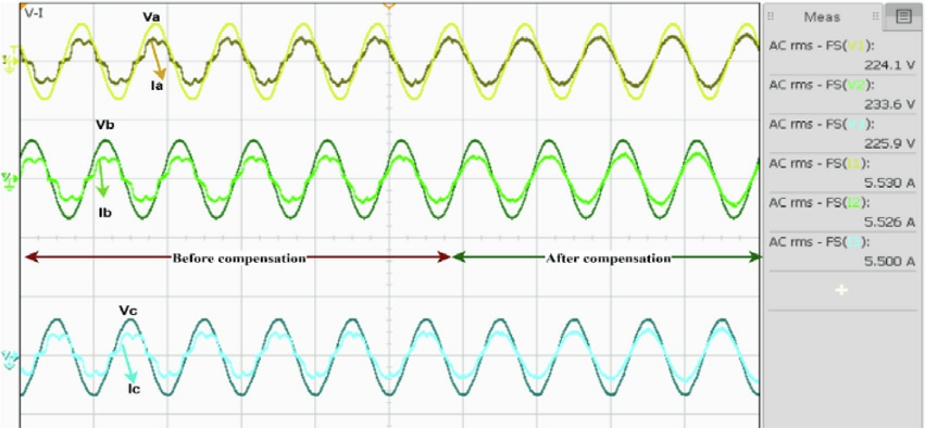
Fig.29.Compensation of reactive demand of nonlinear load.
Fig.30 shows the dynamic relationship between SOC,Voltage,and Current in EV battery.Over a 30-min charging period,G2V operation increases battery SOC from 65% to 78%.V2G operation reduces SOC from 78% to 63% as the battery supplies energy to the grid over 30 min.The controller seamlessly switches the EV between G2V and V2G modes based on SOC.While charging in G2V mode,the battery voltage rises from 395 V and settles at 400 V.In contrast,V2G mode discharges the battery from 400 V to 397.5 V.Between G2V and V2G modes,the battery current reverses polarity.G2V battery current peaks at 5.3 A,indicating charging.In V2G,the battery current becomes positive,indicating discharge,peaking at 6.2 A.The battery current fluctuates slightly with load,demonstrating the system’s adaptability and stability.
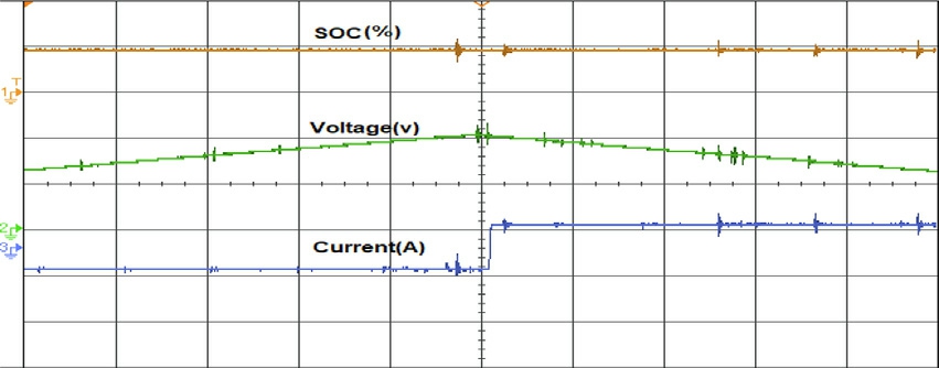
Fig.30.Battery SOC,voltage,and current during G2V and V2G.
A comparative analysis of the PI and ANFIS controllers’ harmonic content,as visualized in Figs.31 and 32 reveal a significant disparity in their performance.The PI controller,despite operating with identical system parameters,introduces a substantial THD of 8.52%.In contrast,the ANFIS controller demonstrates exceptional harmonic mitigation capabilities,producing a THD of only 1.67%.This marked reduction in harmonics is indicative of the ANFIS controller’s superior ability to regulate the system’s voltage and current waveforms Figs.33 an d 34 present the FFT analysis of the PI and ANFIS controllers,respectively,in G2V mode.For the identical system parameter,the PI control ler produces a THD of 9.96%,whereas the ANFIS controller produces a THD of 1.62%.
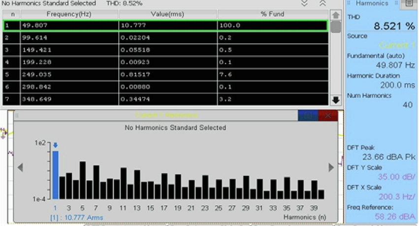
Fig.31.FFT analysis of grid current in v2g mode using PI controller.
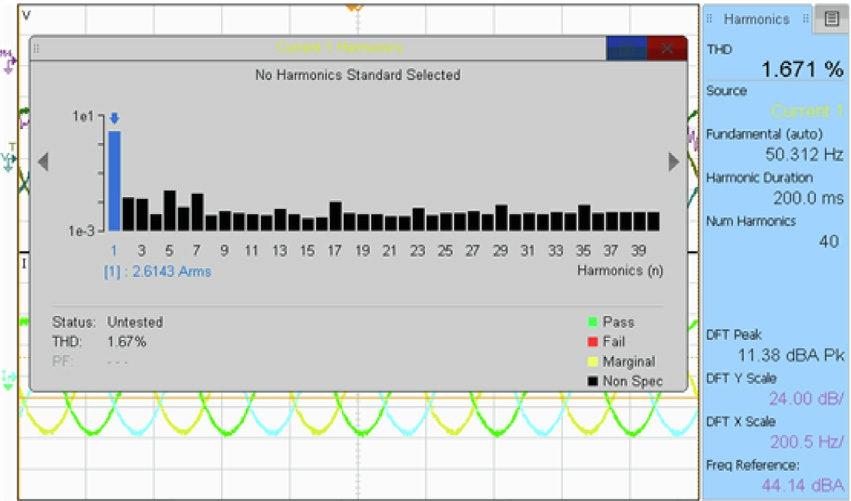
Fig.32.FFT analysis of grid current in v2g mode using ANFIS controller.
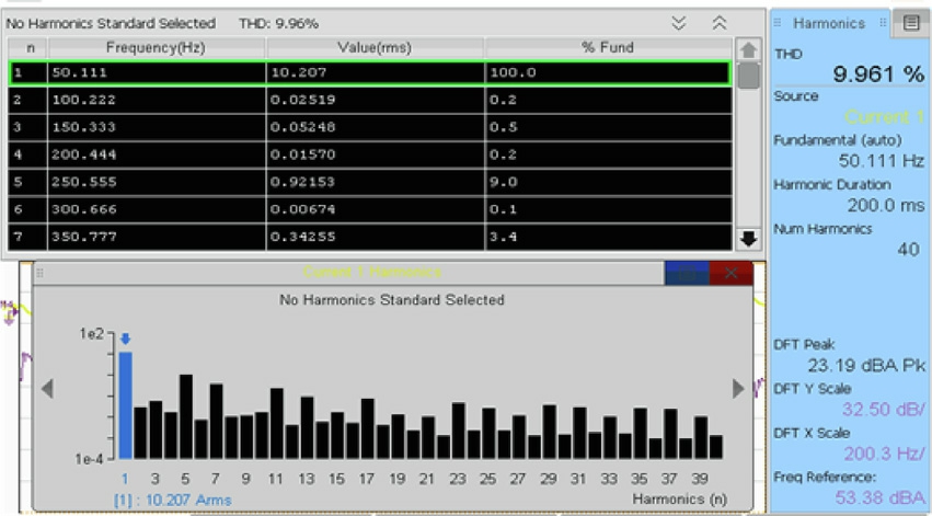
Fig.33.FFT analysis of grid current in G2V mode using PI controller.
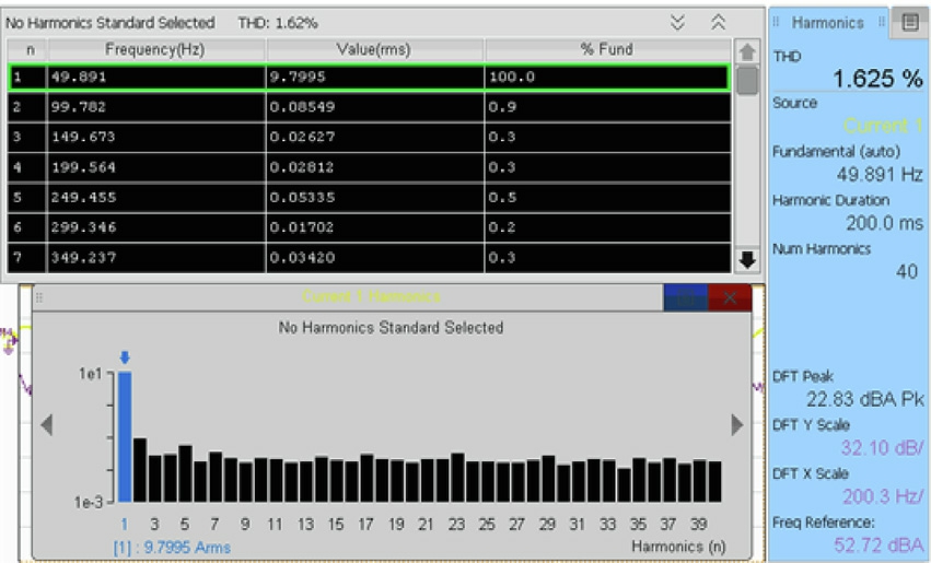
Fig.34.FFT analysis of grid current in G2V mode using ANFIS controller.
PI controller voltage harmonic mitigation was assessed in V2G mode.Fig.35 shows a tabular breakdown of the original grid voltage harmonics,which had 5.74% THD.The spectrum analysis in Fig.36 shows that the suggested ANFIS control strategy greatly reduced harmonic content.THD improved to 4.30%,showing the controller enhanced grid voltage quality.
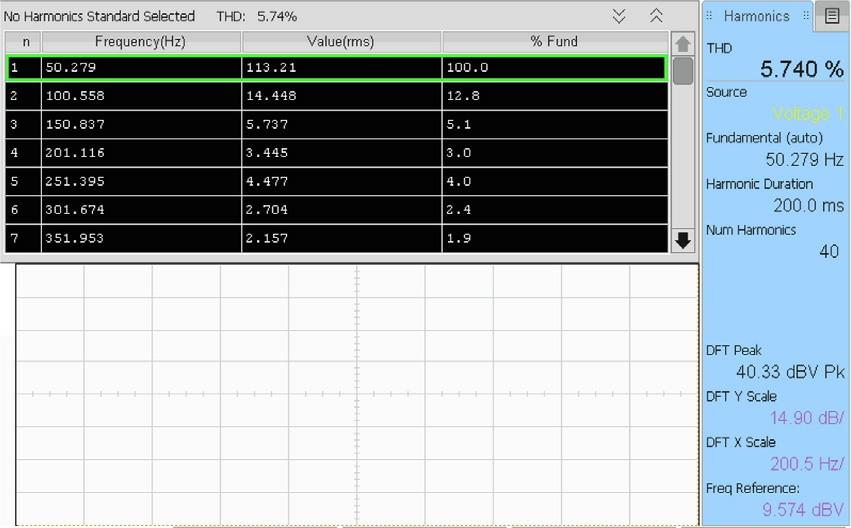
Fig.35.Analysis of grid Voltage in V2G mode using PI controller.
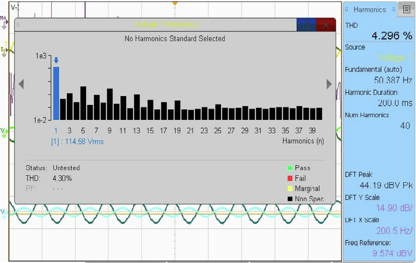
Fig.36.Analysis of grid Voltage in V2G mode using ANFIS controller.
The findings further demonstrate that the charge controller can seamlessly transition between charging and discharging modes and control battery voltage and current in response to user inputs.Fig.37 reveals a clear improvement in THD achieved by the ANFIS controller compared to the PI controller in a V2G application.The acceptable range for grid integration is  5%,as per the standard specified in IEEE 519-2014.This means that the THD value should not exceed 5% for a system to be considered suitable for grid integration.This observation also holds for G2V and V2G simulations and hardware testing.In all cases,the THD values are found to be lower with the ANFIS controller,implying a more sinusoidal flow of current to and from the grid.Thus,the harmonic distortion and consequently the power quality is reduced.This advantage is of great importance in G2V mode because the ability to maintain low THD is more difficult in G2V mode.Overall,these results strongly prove that the THD developed by the ANFIS controller can be reduced to significant levels and also make sure proper DC link voltage under time-varying load operations.
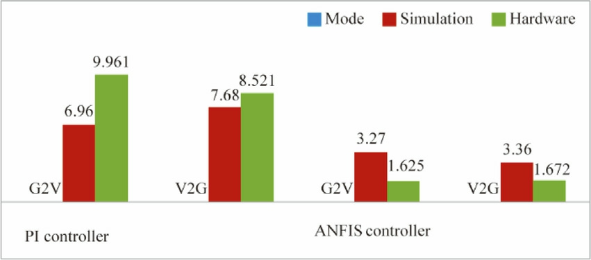
Fig.37.THD Value Based on Controller Performance.
5 Conclusion
In order to facilitate stable grid interaction in both G2V and V2G modes,this work presents an advanced ANFISbased bidirectional charging controller for electric vehicles.The performance of the controller was verified experimentally with a 5 kW prototype and through simulation on a 60 kW setup.When compared to a traditional PI controller,quantitative results show a notable improvement in power quality and dynamic response.The simulation indicates that current THD decreased from 6.76% (PI) to 3.27% (ANFIS) during G2V mode,whereas THD decreased experimentally from 9.96% (PI) to 1.625%(ANFIS).Similarly,the simulation THD decreased from 7.68% (PI) to 3.36% (ANFIS) under V2G mode,and the experimental THD decreased from 8.52% (PI) to 1.67%(ANFIS),both of which were within IEEE 519 limits.The suggested ANFIS controller reduced peak overshoots in both modes and sped up settling times in terms of dynamic performance.Compared to the PI controller,settling time was decreased by more than 25% in simulation and by roughly 20% in hardware tests.These outcomes demonstrate that the suggested ANFIS-based control approach closely matches simulation with actual performance while simultaneously enhancing power quality and dynamic stability.As a result,the system offers a solid and useful framework for EV integration into smart grids,improving grid reliability and encouraging the use of clean energy.
CRediT authorship contribution statement
Nagarajan Munusamy: Writing– original draft,Investigation,Formal analysis,Data curation,Conceptualization.Indragandhi Vairavasundaram: Writing– review &editing,Validation,Project administration,Methodology,Investigation.
Declaration of competing interest
The authors declare that they have no known competing financial interests or personal relationships that could have appeared to influence the work reported in this paper.
Acknowledgment
The authors gratefully acknowledge the financial support provided by the Royal Academy of Engineering,UK (Project Reference No: TSP-2526-7102),which enabled the successful execution of this research work.
References
[1]M.M.Islam,X.Zhong,Z.Sun,H.Xiong,W.Hu,Real-time frequency regulation using aggregated electric vehicles in smart grid,Comput.Ind.Eng.134(2019)11–26,https://doi.org/10.1016/j.cie.2019.05.025.
[2]A.K.Aktar,A.Tas¸cıkaraoğlu,S.S.Gürleyük,J.P.S.Catalão,A framework for dispatching of an electric vehicle fleet using vehicleto-grid technology,Sustain.Energy Grids Netw.33(2023),https://doi.org/10.1016/j.segan.2022.100991.
[3]A.Hussain,P.Musilek,Resilience enhancement strategies for and through electric vehicles,Sustain.Cities Soc.80(2022),https://doi.org/10.1016/j.scs.2022.103788 103788.
[4]P.Cazzola,M.Gorner,R.Schuitmaker,E.Maroney,Global EV outlook 2016,International Energy Agency,France,2016.
[5]S.Abdullah-Al-Nahid,T.A.Khan,M.A.Taseen,T.Jamal,T.Aziz,A novel consumer-friendly electric vehicle charging scheme with vehicle to grid provision supported by genetic algorithm based optimization,J.Energy Storage 50 (2022) 104655.
[6]S.Mittal,A.Singh,P.Chittora,Design and development of reduced switch five Level Inverter for interfacing renewable energy sources and EV charger,Electr.Eng.(2024),https://doi.org/10.1007/s00202-024-02373-0.
[7]T.U.Solanke,P.K.Khatua,V.K.Ramachandaramurthy,J.Y.Yong,K.M.Tan,Control and management of a multilevel electric vehicles infrastructure integrated with distributed resources: a comprehensive review,Renew.Sustain.Energy Rev.144 (2021)111020.
[8]S.Dharmasena,T.O.Olowu,A.I.Sarwat,Bidirectional AC/DC converter topologies: a review,in:2019 SoutheastCon,2019,pp.1–5,https://doi.org/10.1109/SoutheastCon42311.2019.9020287.
[9]F.Justin,G.Peter,A.A.Stonier,V.Ganji,Power quality improvement for vehicle-to-grid and grid-to-vehicle technology in a microgrid,Int.Trans.Electric.Energy Syst.2022(2022),https://doi.org/10.1155/2022/2409188.
[10]M.M.Reda,M.I.Elsayed,M.A.Moustafa Hassan,H.M.Seoudy,Enhancing microgrid renewable energy integration at SEKEM farm,Global Energy Interconnect.7 (6) (2024) 761–772,https://doi.org/10.1016/j.gloei.2024.11.003.
[11]K.Sayed,H.A.Gabbar,Electric vehicle to power grid integration using three-phase three-level AC/DC converter and PI-fuzzy controller,Energies (Basel) 9 (7) (2016) 532.
[12]I.Ahmed,M.Adnan,M.Ali,G.Kaddoum,Supertwisting sliding mode controller for grid-to-vehicle and vehicle-to-grid battery electric vehicle charger,J.Energy Storage 70 (2023) 107914.
[13]T.He,M.Wu,D.-D.-C.Lu,R.P.Aguilera,J.Zhang,J.Zhu,Designed dynamic reference with model predictive control for bidirectional EV chargers,IEEE Access 7 (2019) 129362–129375.
[14]A.Nouri,A.Lachheb,L.El Amraoui,Optimizing efficiency of Vehicle-to-Grid system with intelligent management and ANNPSO algorithm for battery electric vehicles,Electr.Pow.Syst.Res.226 (2024),https://doi.org/10.1016/j.epsr.2023.109936 109936.
[15]H.M.M.Adil,H.A.Khan,WOA-tuned supertwisted synergetic control of multipurpose on-board charger for G2V/V2G/V2V operational modes of electric vehicles,Control Eng.Pract.154(2025),https://doi.org/10.1016/j.conengprac.2024.106136 106136.
[16]S.Mahfoud,A.Derouich,A.Iqbal,N.El Ouanjli,ANT-colony optimization-direct torque control for a doubly fed induction motor: an experimental validation,Energy Rep.8 (2022) 81–98,https://doi.org/10.1016/j.egyr.2021.11.239.
[17]A.Abbasi,F.Alves,R.A.Ribeiro,J.L.Sobral,R.Rodrigues,Optimizing virtual power plants with parallel simulated annealing on high-performance computing,Smart Cities 8(2)(2025),https://doi.org/10.3390/smartcities8020047.
[18]P.Balachennaiah,M.Suryakalavathi,P.Nagendra,Firefly algorithm based solution to minimize the real power loss in a power system,Ain Shams Eng.J.9 (1) (2018) 89–100,https://doi.org/10.1016/j.asej.2015.10.005.
[19]M.K.Banda,S.Madichetty,S.K.Nandavaram Banda,Implementation of deep learning-based bi-directional DC-DC converter for V2V and V2G applications—an experimental investigation,Energies (Basel) 16 (22) (2023) 7614.
[20]F.Nasim et al.,Hybrid ANFIS-PI-based optimization for improved power conversion in DFIG wind turbine,Sustainability 17 (6) (2025),https://doi.org/10.3390/su17062454.
[21]A.Intidam et al.,Development and experimental implementation of optimized PI-ANFIS controller for speed control of a brushless DC motor in fuel cell electric vehicles,Energies (Basel) 16 (11)(2023),https://doi.org/10.3390/en16114395.
[22]M.S.Elborlsy,S.A.Hamad,F.F.M.El-Sousy,R.M.Mostafa,H.E.Keshta,M.A.Ghalib,Neuro-fuzzy controller based adaptive control for enhancing the frequency response of two-area power system,Heliyon (2025),https://doi.org/10.1016/j.heliyon.2025.e42547 e42547.
[23]A.Chub,D.Vinnikov,R.Kosenko,E.Liivik,I.Galkin,Bidirectional DC–DC converter for modular residential battery energy storage systems,IEEE Trans.Ind.Electron.67 (3) (2019)1944–1955.
[24]F.Mohammadi,G.-A.Nazri,M.Saif,A bidirectional power charging control strategy for plug-in hybrid electric vehicles,Sustainability 11 (16) (2019) 4317.
[25]C.Shi,Y.Tang,A.Khaligh,A three-phase integrated onboard charger for plug-in electric vehicles,IEEE Trans.Power Electron.33 (6) (2017) 4716–4725.
[26]V Viswanatha,A.C Ramachandra,Reddy.Venkata Siva,Bidirectional DC DC Converter Circuits and Smart Control Algorithms: A Review,J.Electric.Syst.Inf Technol 9 (2022) 6.
[27]M.E.Meral,D.C¸ elik,Comparison of SRF/PI-and STRF/PRbased power controllers for grid-tied distributed generation systems,Electr.Eng.100 (2018) 633–643.
[28]E.A.Al-Ammar,A.Ul-Haq,A.Iqbal,M.Jalal,A.Anjum,SRF based versatile control technique for DVR to mitigate voltage sag problem in distribution system,Ain Shams Eng.J.11(1)(2020)99–108.
[29]B.Anand,Simulation of PEM fuel cell integrated DVR using SRFANFIS controller for power quality enhancement,J.Eng.Res.9(4A) (2021).
[30]E.Kabalcı,Review on novel single-phase grid-connected solar inverters: circuits and control methods,Sol.Energy 198 (Mar.2020) 247–274,https://doi.org/10.1016/J.SOLENER.2020.01.063.
[31]C.J.O’Rourke,M.M.Qasim,M.R.Overlin,J.L.Kirtley,A geometric interpretation of reference frames and transformations:dq0,clarke,and park,IEEE Trans.Energy Convers.34 (4) (2019)2070–2083.
[32]A.R.Gangula,S.A.Lakshmanan,Design and performance analysis of phase lock loop using ANFIS under non-ideal conditions,in: 2023 International Conference on Advances in Electronics,Communication,Computing and Intelligent Information Systems (ICAECIS),2023,pp.568–575.
[33]M.A.Islam et al.,Modeling and performance evaluation of anfis controller-based bidirectional power management scheme in plugin electric vehicles integrated with electric grid,IEEE Access 9(2021) 166762–166780,https://doi.org/10.1109/ACCESS.2021.3135190.
Received 20 December 2024;revised 20 June 2025;accepted 24 June 2025
Peer review under the responsibility of Global Energy Interconnection Group Co.Ltd.
* Corresponding author.
E-mail address: indragandhi.v@vit.ac.in (I.Vairavasundara m).
https://doi.org/10.1016/j.gloei.2025.06.002
2096-5117/© 2025 Global Energy Interconnection Group Co.Ltd.Publishing services by Elsevier B.V.on behalf of KeAi Communications Co.Ltd.This is an open access article under the CC BY-NC-ND license(http://creativecommons.org/licenses/by-nc-nd/4.0/).

Nagarajan Munusamy completed B.E.in Electrical and Electronics Engineering from Anna University in 2010.He received an M.E.in Control and Instrumentation Engineering from Anna University,Chennai in 2012.Embarking on a career in academia,he has since accumulated 10 years of experience as an Assistant Professor.Subsequently,He is pursuing Ph.D.at Vellore Institute of Technology,Vellore,India.He has been engaged in research work for the past 3 years in the areas of Smart grid,Renewable energy systems,V2G technology and Artificial Intelligence Algorithm.