
0 Introduction
In recent years,distributed resources such as distributed photovoltaics,electric vehicles and their charging facilities,and energy storages have entered a stage of rapid development.In some areas,there have been serious issues with source and load spatio-temporal matc hing and bidirectional power flow safety in the distribution network.Unlike traditional centralized power stations,distributed resources have the characteristics of multiple points,wide area coverage,and high randomness [1–5].In particular,the uncertainty of electric vehicle access makes the distribution network have stronger spatio-temporal dynamic variations.The difficulty of source and load spatiotemporal matching in the new-type distribution network is increasing[6–8].The demand for new electrical network twin analysis applications such as power flow calculation,optimal power flow,economic scheduling,and safety check that integrate the online topology of distributed resources is becoming increasingly urgent [9–13].
The development of traditional distribution network common information model (CIM) has become relatively mature.The object classes described in CIM are essentially abstract and can be used for various applications.The use of CIM also goes far beyond its scope in EMS applications.However,with the development of diversified newtype source,load,and storage resources,the CIM topology model of the new-type distribution network system still needs further research and expansion to support the analysis and application of new-type distribution network.
In the application of digital twin modeling in the field of new-type distribution network,research on device level digital twin modeling of diversified new-type source,including various loads and storage resources has become quite common,and there are some published works about digital twin analysis model for large-scale power grid [11–14].However,research on real-time dynamic construction of new digital twin topology model for distribution network considering distributed resources and their topology models is still in its infancy.Under the rapid development trend of distributed resources such as distributed photovoltaics and electric vehicles,there is an urgent need to research and break through the modelling technology of a new digital twin topology for distribution netwo rk that includes widely dispersed,numerous,and dynamically changing distributed resources in time and space.This will provide technical support for the reliable access and effi-cient consumption of massive distributed resources,as well as the operation analysis and dispatching of new-type distribution network.
Therefore,this article studies the real-time dynamic modelling problem of a new digital twin topology for distribution network,which includes distributed resources such as distributed photovoltaics,energy storages,charging piles,and electric vehicles.The first part expands and establishes a digital twin topology model for distributed resources according to the CIM standard specifications.The second part is based on the digital twin topology model of distributed resources and proposes a new aggregation modelling method for the digital twin topology of distribution network based on spectral clustering [15–18].The third part proposes an online linkage update strategy for the new digital twin topology model of distribution network that integrates real-time topology states.The fourth part conducts case analysis and verifies the feasibility and effectiveness of the method.
1 Distributed resource digital twin topology model
The new-type distributed resources mainly include distributed photovoltaics on the source side,electric vehicles/charging piles on the load side,and new-type energy storage resources.
This section builds up their digital twin topology models.The digit al twin topology model framework is shown in Fig.1.
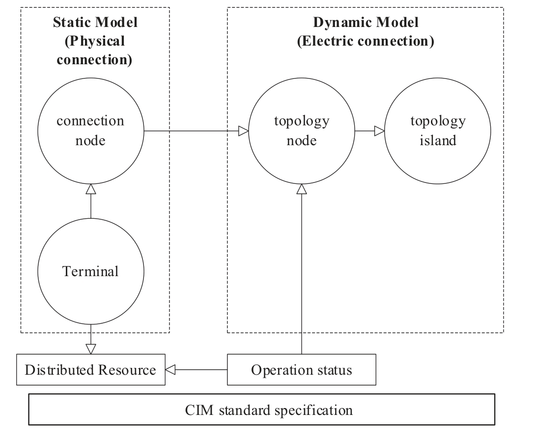
Fig.1.The digital twin topology model framework of the distributed resources.
As shown in Fig.1,the topology models of distributed resources are firstly extended according to the CIM standard specifications,and then combine the real-time operating status of distributed resource to establish its digital twin topology model.The topology model of distributed resource is a static model,whi le its digital twin topology model is a dynamic model that combines real-time operating status.
1.1 Distributed photovoltaics
In the CIM based distribution network topology model,distributed power sources represented by distributed photovoltaics (PV) are used as single terminal devices,with only one terminal,and are connected to existing distribution node (DN) of the distribution network through grid switch (SW).The grid switch s is a dual terminal device,with one end e connected to the distributed photovoltaic p,which belongs to the same connection node as the distributed photovoltaic.The other end b of the grid switch is connected to the existing node n of the distribution network,and its terminals and connection nodes can be modeled as follows:
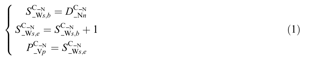
where ![]() is connection node number of the terminal b of the switch s,
is connection node number of the terminal b of the switch s,![]() is connection node number of the terminal e of the switch s,
is connection node number of the terminal e of the switch s,![]() is connection node number of the distribution node n,
is connection node number of the distribution node n,![]() is connection node number of the PV p.
is connection node number of the PV p.
Based on the above model,combined with the real-time status of the grid switch,the topology nodes and topology islands to which the grid switch and distributed photovoltaic belong can be determined.The specific rules are as follows:
1) When the grid switch s is in the closed state![]() according to the CIM model,the connection nodes of the distributed photovoltaic p and its grid switch s belong to the same top ology node(TN) and topology island (TI) as the corresponding existing node n in the distribution network;2) When the grid switch s is in the disconnected state
according to the CIM model,the connection nodes of the distributed photovoltaic p and its grid switch s belong to the same top ology node(TN) and topology island (TI) as the corresponding existing node n in the distribution network;2) When the grid switch s is in the disconnected state![]() the connection nodes of the distributed photovoltaic p belong to different topology nodes and topology islands from the corresponding existing nodes n in the distribution network.
the connection nodes of the distributed photovoltaic p belong to different topology nodes and topology islands from the corresponding existing nodes n in the distribution network.
The above rules can be calculated using the following model:

1.2 Energy storage
Energy storage is integrated into the distribution network through a converter,which is a dual terminal device and a single terminal device for the energy storage battery.However,in grid connected operation and management,the energy storage station (ES) is treated as a whole and is equivalent to a single terminal device,with only one terminal.It is connected to the existing node n of the distribution network through the grid switch s.The grid switch s is a dual terminal device,with one end e connected to the energy storage e,which belongs to the same connection node as the energy storage,while the other end b of the grid switch is connected to the existing node n of the distribution network.It can be seen that the connection node model of the grid connected switch is the same as that of the distributed photovoltaic grid connected switch,and the energy storage connection node model is modeled as follows:
where ![]() is connection node number of the ES e.
is connection node number of the ES e.
Based on the above model,combined with the real-time status of the grid switch,the topology nodes and islands to which the grid switch and energy storage belong can be determined.The specific rules are as follows:
1) When the grid switch s is in the closed state,according to the CIM model,the connection nodes of the energy storage e and its grid switch s belong to the same topology node and topology island as the corresponding existing node n in the distribution network;
2) When the grid switch s is in the disconnected state,the connection node of the energy storage e belongs to a different topology node and topology island from the corresponding existing node n in the distribution network.
According to the above rules,a topology model for grid connected switches and energy storage can be established.The topology model for grid connected switches is the same as that for distributed photovoltaic grid connected switches.The energy storage topology model is represented as follows:
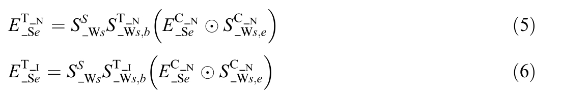
where ![]() is topology node number of the ES e,
is topology node number of the ES e,![]() is topology island number of the e.
is topology island number of the e.
1.3 Electric vehicle and charging pile
Charging piles (CP) are dual terminal devices,while electric vehicles (EV) are single terminal devices.The begin terminal b of charging pile p is connected to the existing node n of the distribution network through the grid switch s.The grid switch s is a dual terminal device,with one end e connected to the charging pile p,which belongs to the same connection node as the charging pile,while the other end b of the grid switch is connected to the existing node n of the distribution network.The end e of charging pile p is connected to electric vehicle v,which belongs to the same connection node as the electric vehicle.It can be seen that the connection node model of the grid connected switch is the same as that of the distributed photovoltaic grid connected switch,and the connection node models of the charging pile and electric vehicle are modeled as follows:
where ![]() is connection node number of the terminal b of the charging pile p,
is connection node number of the terminal b of the charging pile p,![]() is connection node number of the terminal e of the charging pile p,
is connection node number of the terminal e of the charging pile p,![]() is connection node number of the EV v.
is connection node number of the EV v.
Based on the above model,combined with the real-time status of the grid switch s,as well as the access and working status of electric vehicle v and charging pile p,the topology nodes and islands to which electric vehicle v and charging pile p belong can be determined.The specific rules are as follows:
1) When the grid switch s is in the closed state,according to the CIM model,the connection nodes of the charging pile p and its grid switch s belong to the same topology node and topology island as the corresponding existing node n in the distribution network.When an electric vehicle v is connected and the charging pile p is in operation,the charging pile p and the corresponding grid switch s belong to the same topology node and topology island,and the terminal connected to the electric vehicle v by the charging pile p also belongs to the same topology island,but belongs to different topology nodes;
2) When the grid switch s is in the disconnected state,the connection node of the charging pile p belongs to a different topology node and topology island from the corresponding existing node n in the distribution network.When there is no electric vehicle connected and the charging station is in standby or shutdown state,the charging pile p and the corresponding the grid switch s belong to different topology nodes and topology islands,and the terminal connected to the electric vehicle by the charging pile p also belongs to different topology nodes and topology islands.
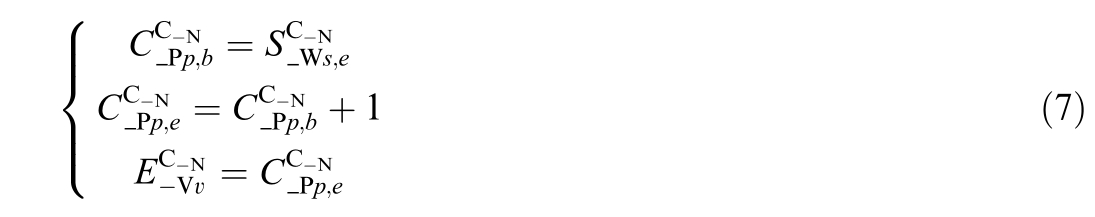
The above rules can be calculated using the following model:
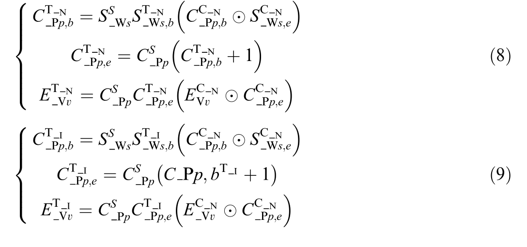
where![]() is topology node number of the terminal b of the charging pile p,
is topology node number of the terminal b of the charging pile p,![]() is topology node number of the terminal e of the charging pile p,
is topology node number of the terminal e of the charging pile p,![]() is topology node number of the EV v.
is topology node number of the EV v.![]() is the state variable of the charging pile p, with 1 indicating charging,0 indicating free,
is the state variable of the charging pile p, with 1 indicating charging,0 indicating free,![]() is topology island number of the terminal b of the charging pile p,
is topology island number of the terminal b of the charging pile p,![]() is topology island number of the terminal e of the charging pile p,
is topology island number of the terminal e of the charging pile p,![]() is topology island number of the EV v.
is topology island number of the EV v.
2 Digital twin topology model for a new-type distribution network based on spectral clustering
On the basis of constructing a digital twin topology model for distributed resource,combined with existing topology model of distribution network,a new aggregation modelling method for digital twin topology model of distribution network based on spectral clustering is proposed to construct a new digital twin topology model of distribution network containing new-type distributed resources.The flowchart of building the digital twin topology model for a new-type distribution network is shown in Fig.2.
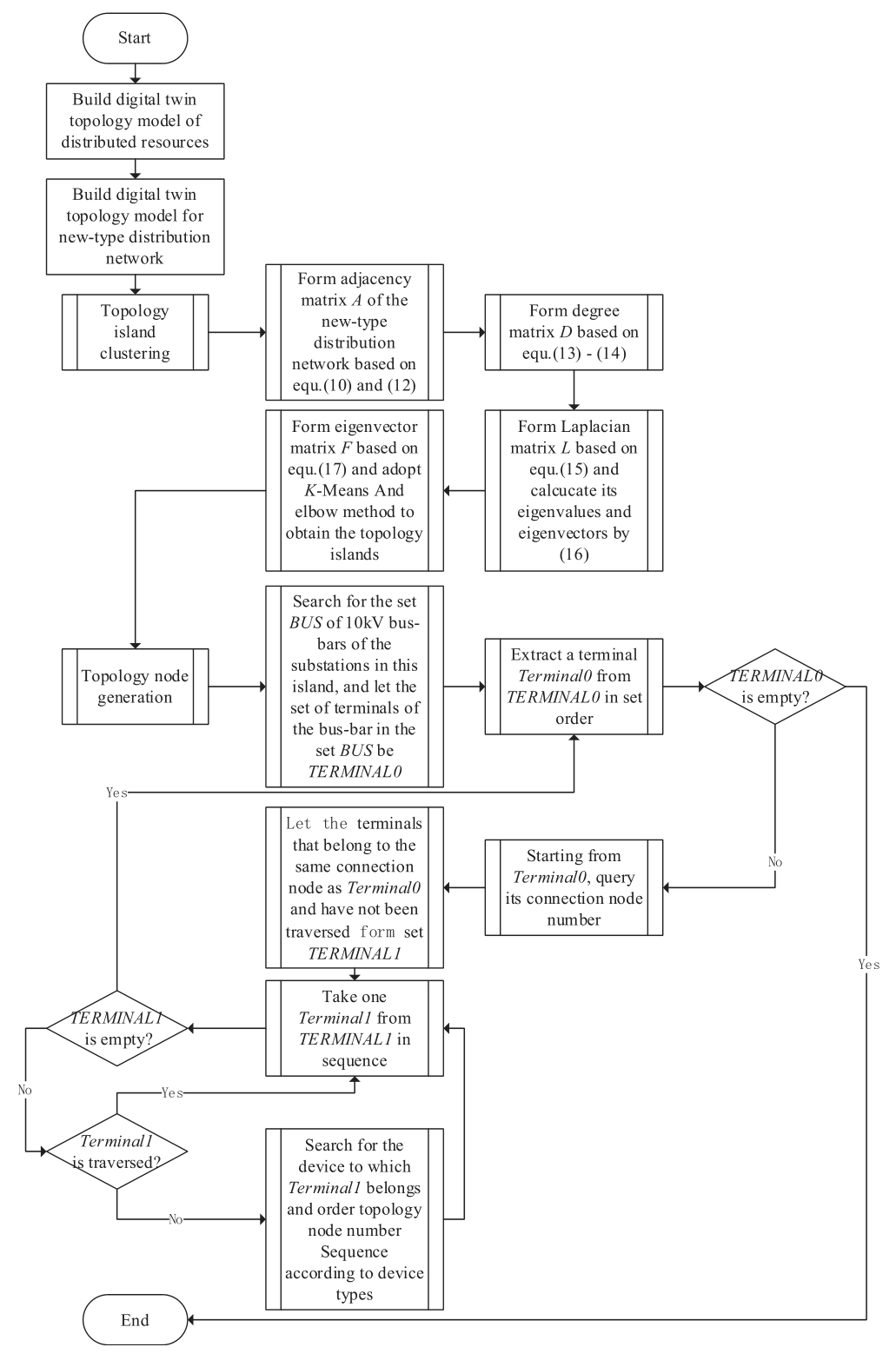
Fig.2.The flowchart of building the digital twin topology model for a new-type distribution network.
2.1 Spectral clustering method
The spectral clustering algorithm regards each object in the style="font-style: italic;">V of the graph,quantifies the similarity between vertices as the weight of the corresponding vertex connected edge E,and obtains an undirected weighted graph G (V,E) based on similarity.Therefore,the clustering problem can be transformed into a graph partitioning problem.The optimal partitioning criterion based on graph theory is to maximize the similarity within the sub-graphs and minimize the similarity between subgraphs.
Although spectral clustering algorithms have different specific implementation methods based on different criterion functions and spectral mapping methods,the basic process of spectral clustering can be summarized into the following four main steps:
A.For a given graph G(V,E),calculate the degree matrix D and adjacency matrix A of the graph;
B.Calculate the Laplacian matrix L=D-A for graph G;
C.Perform eigenvalue decomposition on the Laplacian matrix,take the eigenvectors corresponding to the first k eigenvalues,and form the eigenvector matrix K;
D.Use K-means clustering algorithm to cluster the feature vector matrix K mentioned above,where each row in the feature vector matrix K represents a sample to be clustered.
2.2 Digital twin topology modelling
In order to support network analysis applications,it is necessary to construct a new digital twin topology model for distribution network,which is based on the connection node model in the new distributed resource digital twin topology model.According to the principle and basic steps of the spectral clustering method mentioned above,a new aggregation construction method for the digital twin topology model of distribution network is proposed.Firstly,the spectral clustering method is used to obtain the sub-graph partitioning results,which includes the number of physical topology islands in the entire network partition,as well as the source,network,load,and storage devices contained in each physical topology island.Then,for each sub-graph/physical topology island,based on the existing breadth first search topology analysis method in the distribution network,according to the topology nodes and electrical topology island models in the digital twin topology model of distributed resources mentioned above,the topology node models within each sub-graph/physical topology island are constructed.
2.2.1 Topology island clustering
In the implementation of spectral clustering method,the terminals of various types of equipment such as sources,network devices,loads,and storage in the newtype distribution network are taken as the vertex V of graph G.The similarity between the vertices is determined by whether the two terminals belong to the same connection node.If they are the same,the similarity is 1,otherwise 0.This similarity is used as the weight of the corresponding vertex connection edge E to construct an adjacency matrix.
The adjacency matrix A is defined as follows:
where N T is the total number of terminals for the sources,network devices,loads,and storage in the entire system,aij is the adjacency variable for terminal vi and terminal vj,which is 1 when the two terminals of different devices belong to the same connection node,otherwise it is 0;For different terminals of the same device,they are considered to be adjacent to each other,that is:
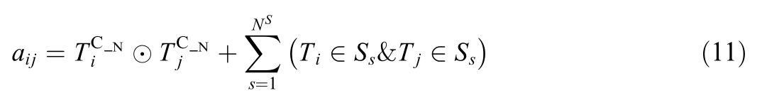
where ![]() are the connection node numbers of the terminals Ti \T j,NS is the total number of sources,network devices,loads,and storage in the entire system,Ss is the sth device,and
are the connection node numbers of the terminals Ti \T j,NS is the total number of sources,network devices,loads,and storage in the entire system,Ss is the sth device,and  is the logical operator.
However,for switch devices,it is also necessary to judge their open or closed state.When the switch state is closed,the terminals on both sides belong to the same connection node and are adjacent to each other.When the switch state is open,the terminals on both sides do not belong to the same connection node and are not adjacent to each other.That is,formula (11) should be rewritten as:
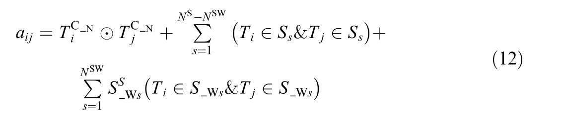
where N SW is the number of switch devices in the entire system,and ![]() is the sth switch device.
is the sth switch device.
The degree matrix D of graph G is defined as follows:
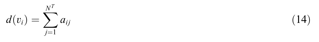
The degree matrix D is a diagonal matrix,and the values of its main diagonal are the degrees of vertex vi,that is:
The Laplacian matrix L of Figure G is defined as:
Let λ i be the eigenvalue of the Laplacian matrix L,fibe the eigenvector corresponding to the eigenvalue λi,which follow the equ ation below:
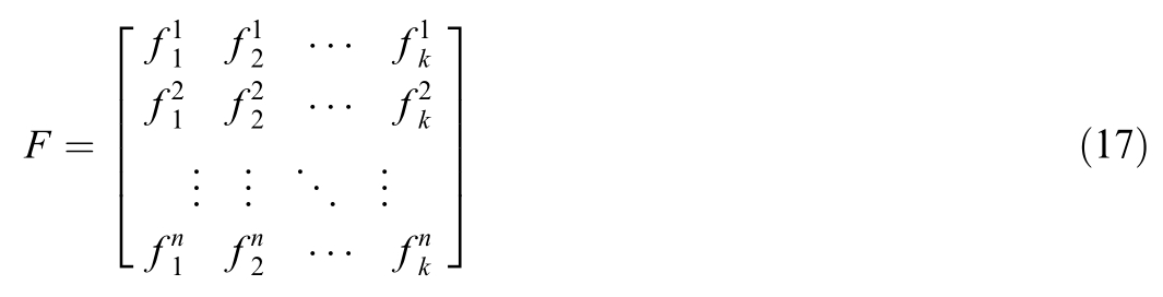
In the sub-graph clustering based on spectral clustering,if the clusters are k sub-graphs,the first k eigenvectors of the Laplacian matrix L are taken to form the eigenvector matrix F.Then,the K-Means clustering method is used to cluster the eigenvector matrix F.During clustering,each row in the eigenvector matrix F represents a sample.
The elbow method is used to determine the final value of k,that is,by using K-Means clustering and observing the change of the sum of squared errors with k.Usually,there is a significant decrease in k after it increases to a certain point,which is called the“elbow”.The corresponding value of k at the “elbow” point is selected as the optimal number of clusters.
2.2.2 Topology node generation
Based on the determined sub-graph partitioning results,namely the connected physical topology islands,for each sub-graph,a breadth-first search algorithm is used to construct the topology node models within each sub-graph/physical topology island according to the electrical topology nodes and topology island models in the digital twin topology model of distributed resources mentioned above.Among them,starting from the 10 kV bus-bar of the substation,the specific process is as follows:
1) Search for the set BUS of 10 kV bus-bars in the substation of this sub-graph/physical topology island,where the set of terminals for each bus-bar in the BUS forms TERMINAL0;
2) Extract a terminal Terminal0 from TERMINAL0 in set order;End when TERMINAL0 is empty;
3) Starting from Terminal0,query the connection node number of this terminal;
4) Let the terminals that belong to the same connection node as Ter minal0 and have not been traversed form set TERMINAL1;
5) Take one Terminal1 from TERMINAL1 in sequence;Until TERMINAL1 is empty,return to step 2;
6) If Terminal1 has already been traversed,skip it and return to step 5;Otherwise,search for the device to which Terminal1 belongs and query the device type of the device;
(1) If the device type is a line segment,distribution transformer,charging station,or energy storage converter,query the ope rating status of the line segment/distribution transformer/charging station/energy storage converter;
A. If the operating status is normal,then make Terminal1 and the current Terminal0 belong to the same topology node and topology island;If another Terminal2 of the line segment/distribution transformer/charging pile/energy storage converter has not been traversed,then its topology node number is equal to Terminal1 s topology node number+1 and belongs to the same topology island;Add Terminal2 to TERMINAL0;If it has already been traversed,skip this Terminal2;Returning to step 5;
B.If the running status is faulty or exited,skip Terminal1 and do not process it;Returning to step 5;
(2) If the equipment type is load,reactive power compensator,distributed photovoltaic,electric vehicle,energy storage battery,query the operating status of the load/reactive power compensator/distributed photovoltaic/electric vehicle/energy storage converter;
A.If the operating status is normal,then make Terminal1 and the current Terminal0 belong to the same topology node and topology island;Returning to step 5;
B.If the running status is faulty or exited,skip Terminal1 and do not process it;Returning to step 5.
3 Topology online update strategy
During real-time operation,when the operating status of a device changes,the topology island of the system will correspondingly change.Due to the long time required for spectral clustering mentioned above,it cannot meet the real-time requirements for online linkage updates of digital twins in the distribution network when the device topology changes.Therefore,in order to avoid topology regeneration of the entire system due to changes in device operating status,and based on the impact mechanism of real-time device status changes on the digital twin topology model of the distribution network,a corresponding online linkage update strategy for the digital twin topology model of the distribution network is proposed.The specific steps are as follows:
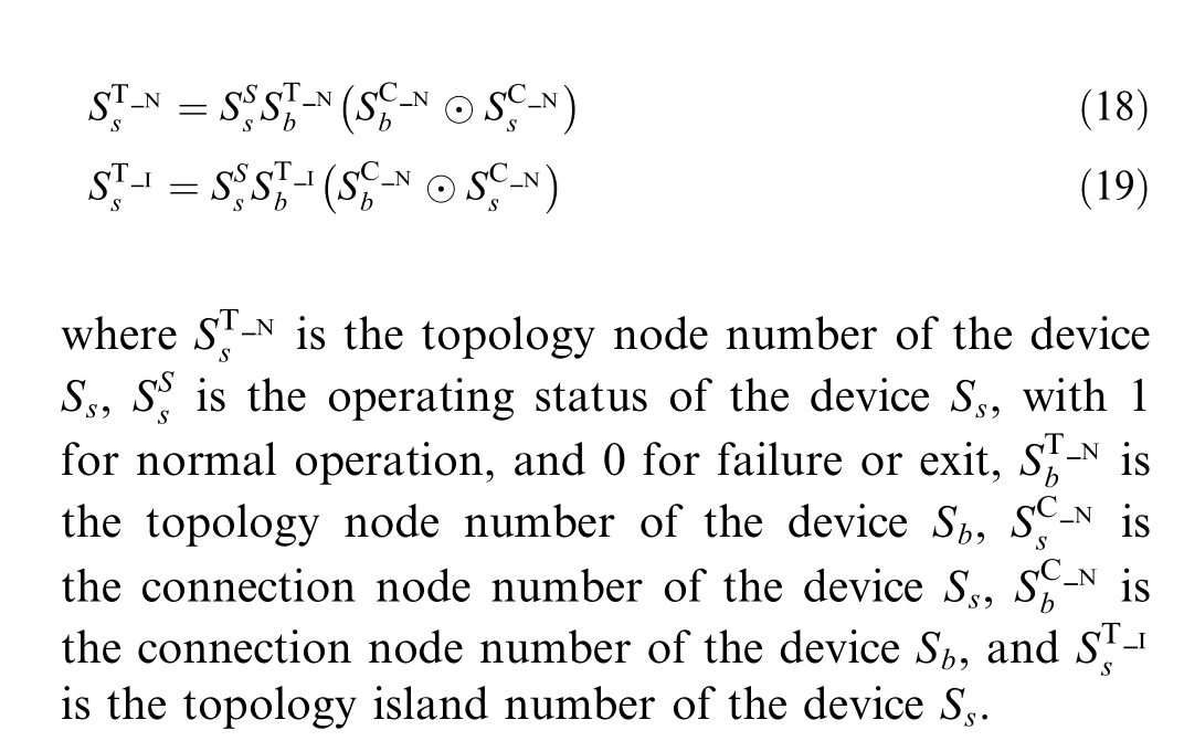
1) If equipment such as loads,reactive power compensators,distributed photovoltaics,electric vehicles,energy storage batteries,etc.fail or exit,their topology nodes and corresponding topology island information need to be deleted;If equipment are put into use,it is necessary to search for the connection nodes of the equipment and their corresponding topology node numbers and topology islands,and make the equipment belong to the same topology node number and topology island;The topology model of this type of device has been updated as follows:
2) If the switches change from closed to open,the topology nodes at both ends and the topology island information it belongs to need to be deleted,and all devices within the topology island need to be traversed.Based on the connection relationship,it is determined whether the device can reach the 10 kV bus-bar of the substation on the topology island.If it is not reachable,the topology nodes and topology island information of the device need to be deleted.If it is reachable,it remains unchanged.The reachable matrix is calculated as follows:
where N T is the total number of terminals of all devices in the topology island to which the switch belongs,A is the adjacency matrix of all devices in the topology island,and R is the reachable matrix of all devices in the topology island.If the element is not 0,it is reachable,and if it is 0,it is unreachable.
For the element r1j with a value of 0,which is the reachable variable between the10 kVbus-bar of the substation on this topology island as the starting terminal (terminal number 1) and the terminal vj of other devices,a value of 0 indicates unreachable.Therefore,the corresponding devices need to be removed from this topology island,and the corresponding topology model is updated as follows:
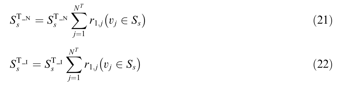
where vj  S s represents that terminal vj belongs to the device.
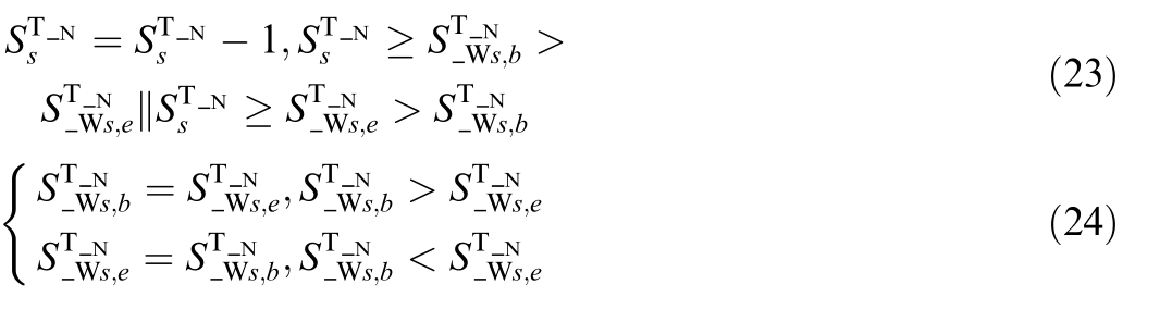
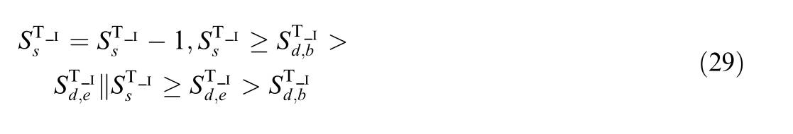
If the switches change from open to closed,the topology node numbers and topology islands to which the connection node numbers of the terminals on both sides of the switch belong need to be merged.The topology node numbers and topology islands of the terminals on both sides will be merged into one,and the topology node numbers of other topology nodes within the two topology islands need to be updated in the original order.There are two situations based on whether the topology island numbers of the terminals on both sides are the same:
(1) Same topology islan d
For the case where both ends of the switch belong to the same topology island,after the switch is closed,it is only necessary to unify the topology node numbers of the terminals on both sides of the switch,and update the other topology node numbers after that topology node number,that is:
(2) Different topological island s
For the case where the two ends of the switch belong to different topological islands,after the switch is closed,the other topological nodes in the two topological island s need to be updated in the original order,including the topological node number and the topological island number,that is:
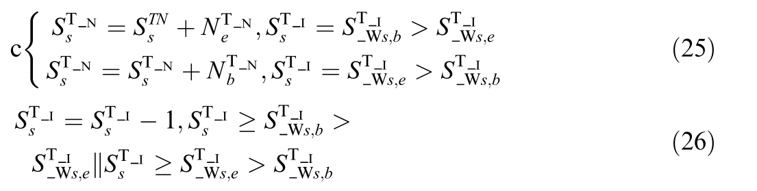
where ![]() is the number of topological nodes of the topological island to which the switch end b belongs,and
is the number of topological nodes of the topological island to which the switch end b belongs,and ![]() is the number of topological nodes of the topological island to which the switch end e belongs.
is the number of topological nodes of the topological island to which the switch end e belongs.
Meanwhile,it is necessary to unify the topology node number and topology island number of the terminals on both sides of the switch.The topology node number unification method is the same as formula (24),and the topology island number unification formula is as follows:
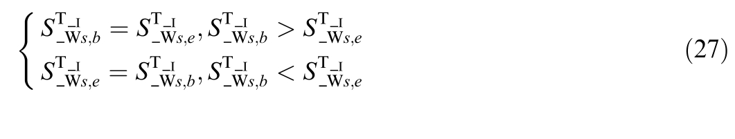
(3) If equipment such as line segments,distribution transformers,charging piles,or energy storage converters fail or exit,the topology nodes and island information at both ends need to be deleted,and all devices within the topology island need to be traversed.Based on the connection relationship,it is determined whether the device can reach the 10 kV bus-bar of the substation on the topology island.If it is not reachable,the topology nodes and island information of the device need to be deleted.If it is reachable,it remains unchanged.The update formula in this case is the same as (20)–(22).
If equipment such as line segments,distribution transformers,charging stations,or energy storage converters are restored to operation and put into use,the topology island and its included topology nodes to which the connection node numbers of the terminals on both sides of the equipment belong need to be updated.According to whether the topology island numbers of the terminals on both sides of the device are the same,there are also two situations:
(1)Same topology island
For the case where both ends of the device belong to the same topology island,after the device is put into operation,it does not affect the existing topology island division and topology node number,that is,there is no need to update.
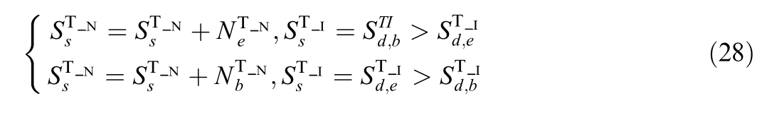
(2) Different topological islands
For the case where the two ends of device d belong to different topology islands,after the device is put into operation,the two topology islan ds need to be unified,and the topology nodes need to be updated in the original order,that is:
4 Case study
Based on the distributed resource digital twin topology model and the new-type distribution network digital twin topology model construction method based on spectral clustering established in this article,as well as the online linkage update strategy of the new-type distribution network digital twin model that integrates real-time topology status,a case study analysis and algorithm verification were conducted for a demonstration distribution system scenario in a certain region of China.
4.1 Study system
A distribution system with three feeder s,as shown in Fig.3,is studied to verify the proposed digital twin topology modelling method of the new-type distribution network based on CIM specifications and spectral clustering.Each of three feeders is improved by standard IEEE 33-node distribution system,with 31 nodes,32 nodes,and 33 nodes for each feeder,respectively.The distributed PVs are integrated into the feeders at nodes 2,8,12,16,20,23,and 30 of each feeder.Nodes 6,10,and 15 of each feeder are connected with an independent energy storage system.Node 8 and 14 of each feeder are connected with an electric vehicle charging pile.Besides,there are two linkage switches among there feeders.Switch A is linking node 6 of feeder A and node 8 of feeder B,and switch B is linking node 15 of feeder B and node 12 of feeder C.
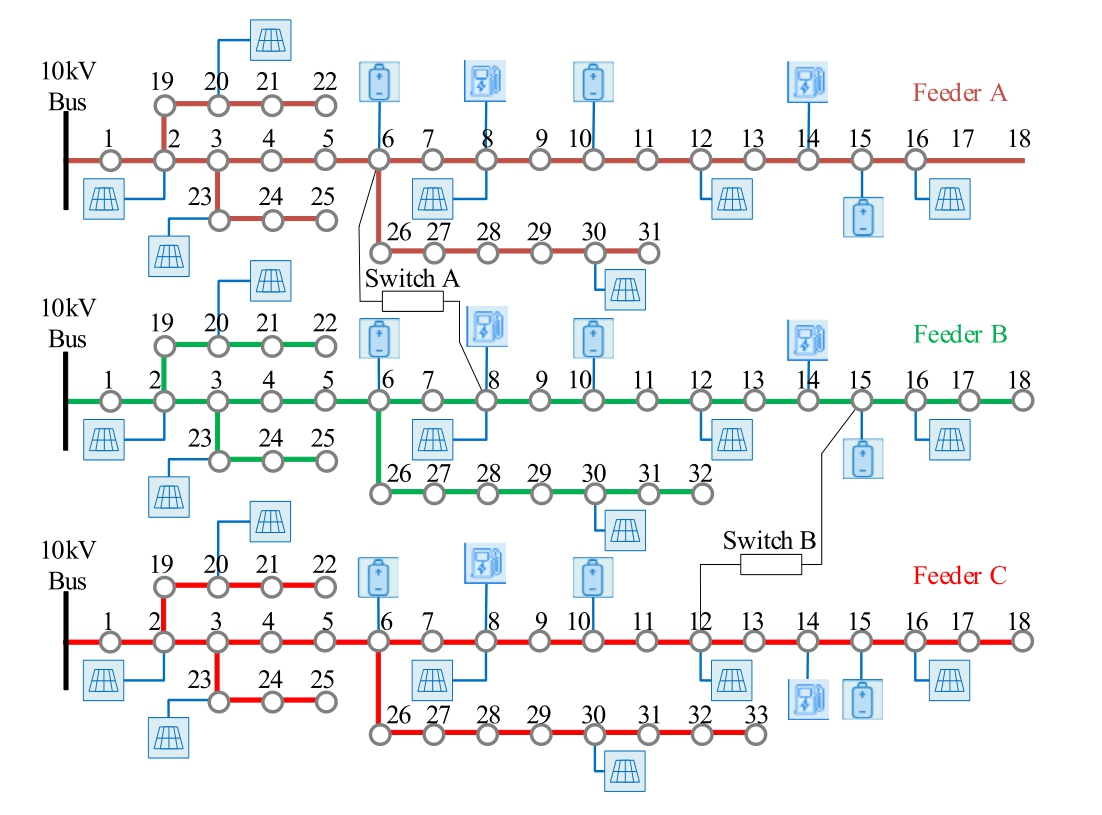
Fig.3.The study substation system with there improved IEEE 33-node feeders.
Normal operation mode: refer to the above study system,both switches are normally open;the PVs usually start generation at 6:00 and stop at 19:00;The operation curves of the energy storage systems at different nodes of all the three feeders are shown in Fig.4;And the operation curves of the electric vehicle charging piles at different nodes are shown in Fig.5.
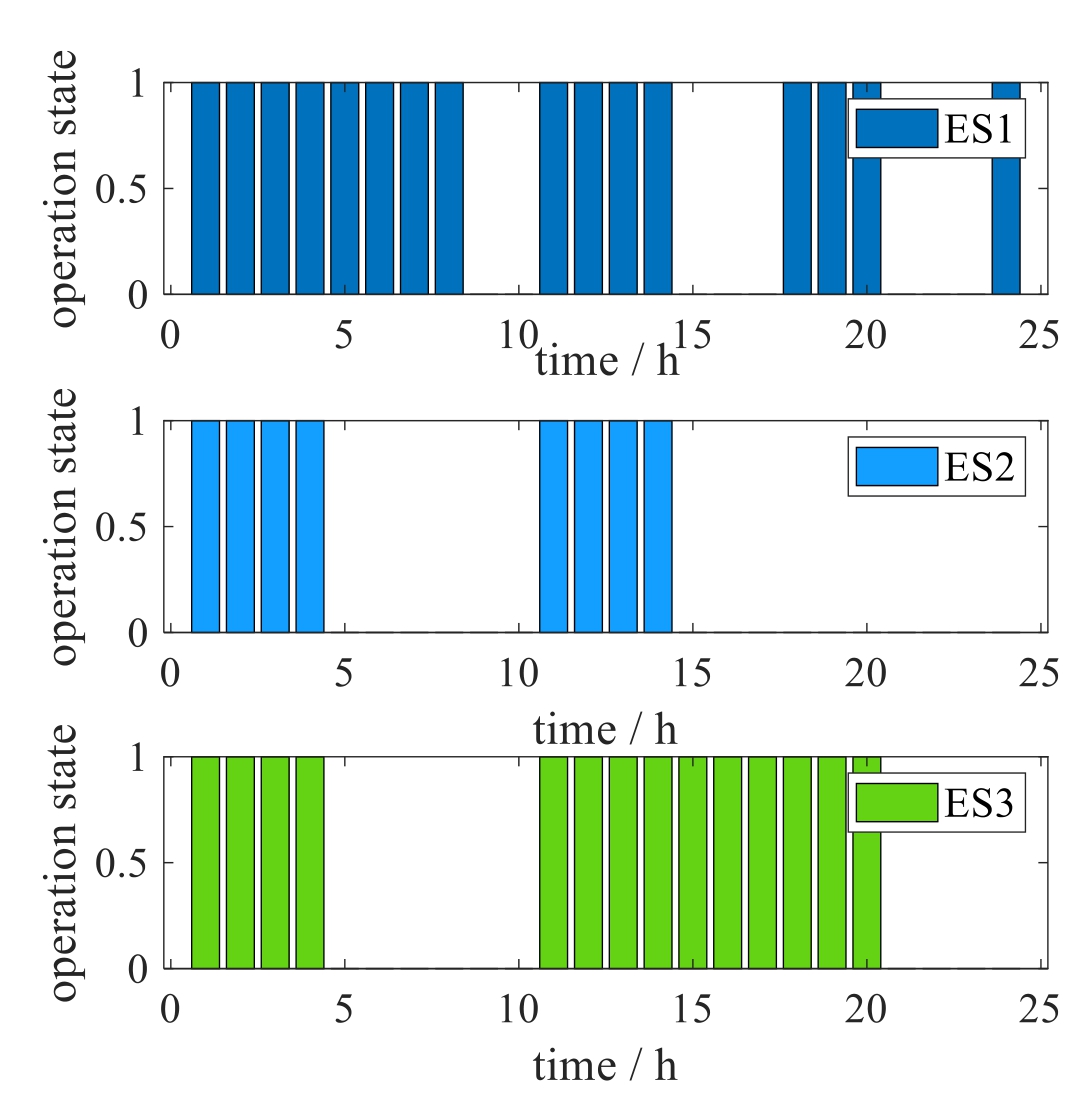
Fig.4.The operation curves of the energy storage systems.
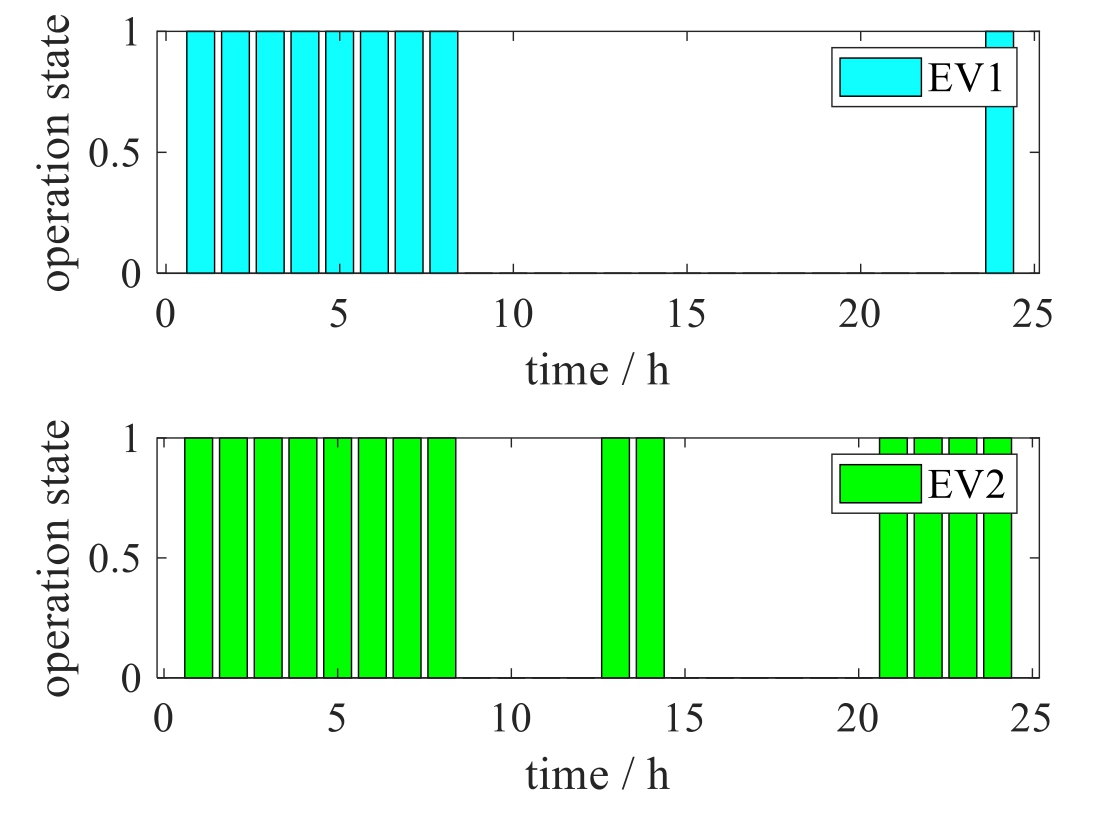
Fig.5.The operation curves of the electric vehicle charging piles.
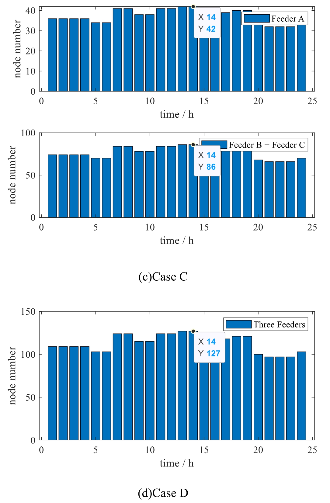
Fig 6. (continued)
Given the above study system,several different cases considering different operation states of the PVs,energy storages,electric vehicle charging piles,and linkage switches are carried out in this paper to verify the effectiveness of the proposed modelling method.
Case A: Normal operation mode.
Case B: Switch A is closed.
Case C: Switch B is closed.
Case D: Both switch A and B are closed.
4.2 Results and analyses
For the above example objects,the method described in this article is used to model the distributed resource digital twin topology,and then cluster to constr uct a new-type distribution network digital twin topology model.The overall results of topology island clustering modeling are shown in Table 1.
Table 1 Topology island clustering results of the study system.
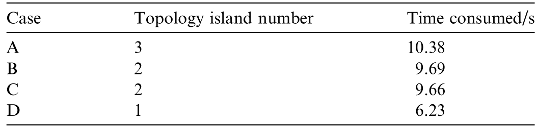
As shown in Table 1,the new digital twin topology model construction method based on spectral clustering can correctly construct topology island structures for dif-ferent operating modes of the new-type distribution network.
Among them,the topology node generation results for distributed resources including solar photovoltaics,energy storage systems and electric vehicle charging piles under different operating states and scenarios in 24 h are shown in Fig.6,and the topology online update time at each hour is shown in Table 2.
Table 2 Topology online update time of the study system.
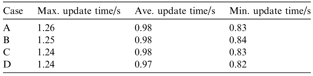
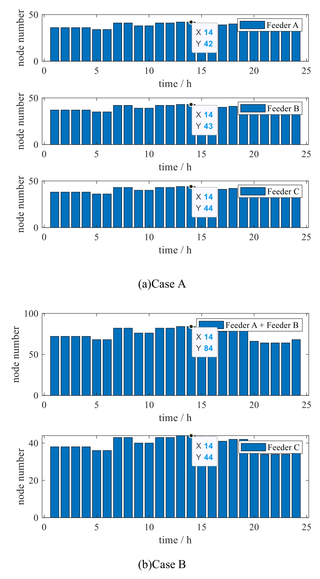
Fig.6.Topology node generation results of the study system.
As shown in Fig.6,the distributed resource digital twin topology model can achieve online rapid linkage updates of the new distribution network digital twin topology model based on real-time topology changes of different types of devices.In scenario A,the number of topology nodes for each topology island at different times is shown in Fig.6(a).Due to the input and output of devices such as energy storage systems and electric vehicle charging piles,the number of topology nodes at different times follows the rules of their input and output,resulting in changes in topology nodes.In scenario B,due to the closure of switch A,feeder A and feeder B form a topological island,and their topological nodes merge accordingly.Therefore,the number of nodes is the same as the number of nodes after the merger of the two topological islands.Moreover,due to the closure of switch A,node 6 of feeder A and node 8 of feeder B merge into one node,so the number of nodes after the merger of the two topological islands is less than the sum of the number of nodes in the original two topological islands.Similarly,in scenario C,due to the closure of switch B,feeder B and feeder C form a topological island,and their topological nodes merge accordingly.Therefore,the number of nodes is the same as the number of nodes after the merger of the two topological islands.Moreover,due to the closure of switch B,node 15 of feeder B and node 12 of feeder C merge into one node,so the number of nodes after the merger of the two topological islands is less than the sum of the number of nodes in the original two topological islands.As for the case D,since switches A and B are both closed,feeder A,feeder B,and feeder C form a topological island as a whole,and their topological nodes are merged accordingly.Therefore,the number of nodes is the same as the number of nodes after the merger of the three topological islands.Moreover,since switches A and B are closed,node 15 of feeder B and node 12 of feeder C are also merged into one node.Therefore,the number of nodes after the merger of the three topological islands is less than the sum of the number of nodes in the original three topological islands.
As shown in Table 2,in the above four scenarios,with the input and output of devices such as energy storage systems and electric vehicle charging piles at different times,the number of topology nodes in each scenario conforms to the topology node changes brought by their input and output rules.It can integrate real-time status for online linkage updates of the new-type distribution network digital twin topology model,with update time only seconds and an average update time of less than 1 s,verifying the effectiveness and real-time performance of the method described in this paper.
5 Conclusion
This article studies the real-time dynamic modelling method of a new digital twin topology for distribution network,which includes distributed resources such as distributed photovoltaics,energy storages,charging piles,and electric vehicles.A new digital twin topology modeling method for distribution network based on CIM specifications and spectral clustering is proposed.Case an alysis and algorithm validation are completed using operational data of the distribution network with distributed photovoltaics,energy storages,charging piles,and electric vehicles in a demonstration zone in China,and the following conclusions are obtained.
1) The distributed resource digital twin topology model can update its digital twin topology model online based on real-time topology changes of different types of devices.
2) The construction method of a new digital twin topology model for distribution network based on spectral clustering can correctly constr uct topology islands for different operating modes of the new-type distribution network.
3) The online linkage update strategy of the new-type distribution network digital twin topology model that integrates real-time status can quickly update the distribution network digital twin model in real time according to the real-time topology changes of different types of equipment and changes in the operation mode of the new-type distribution network.
CRediT authorship contribution statement
Zhimin He: Writing– original draft,Investigation,Writing– review &editing.Hai Yu: Writing– original draft.Lin Peng: Writing– original draft,Data curation.Aihua Zhou: Resour ces,Writing– original draft. He Wang: Investigation,Writing– original draft. Jin Xu: Investigation,Writing– original draft.
Declaration of competing interest
The authors declare the following financial interests/personal relationships which may be considered as potential competing interests: Zhimin He,Hai Yu,Lin Peng are currently employ ed by State Grid Smart Grid Research Institute Co.,LTD.The research project is funded by State Grid Corporation of China.
Acknowledgments
Supported by Science and Technology Project of State Grid Corpor ation of China (5108-202218280A-2-396-XG).
References
[1]X.H.Chen,S.F.Li,F.S.Wang,et al.,Power estimation method of low-voltage distributed photovoltaic generation based on similarity aggregation,Energy Rep.7 (2021) 1344–1351.
[2]F.Li,F.Wu,X.Zhang,et al.,Research on polymerization equivalent modeling in large: Scale photovoltaic power plant,in:Proceedings of IECON 2017– 43rd Annual Conference of the IEEE Industrial Electronics Society,Beijing,China,2017,pp.2664–2668.
[3]C.Chen,Z.Wenyue,et al.,Method for potential analysis and evaluation of water PV power generation within a province,Journal of Global Energy Interconnection 6 (1) (2023) 33–44.
[4]H.H.Bian,J.S.Sun,Photovoltaic power generation prediction model based on optimized TMY method-GRNN,Electr.Power Eng.Technol.40 (5) (2021) 94–99.
[5]S.Jiang,H.Gao,X.Wang,J.Liu,Deep reinforcement learning based multi-level dynamic reconfiguration for urban distribution network: a cloud-edge collaboration architectu re,Global Energy Interconnect.6 (1) (2023) 1–14.
[6]W.J.Zhang,J.S.Wang,Research on V2G control of smart microgrid,in: Proceedings of 2020 Internatio nal Conference on Computer Engineering and Intelligent Control (ICCEIC),Chongqing,China,2020,pp.216–219.
[7]Z.H.Liu,Y.B.Zhou,C.Jin,Optimization strategy study on installation mix of renewable energy power base for supporting outbound delivery,Journal of Global Energy Interconnection 6(2)(2023) 101–112.
[8]K.Xiao,D.Li,P.Guo,et al.,Similarity matching method of power distribution system operating data based on neural information retrieval,Global Energy Interconnect.6 (1) (2023)15–25.
[9]L.Wang,F.Zhang,L.Kou,et al.,large-scale distributed PV cluster division based on fastunfolding clustering algorithm,Acta Energiae Solaris Sinica 42 (10) (2021) 29–34.
[10]X.K.Hu,R.Yin,M.Shi,et al.,Distributed photovoltaic cluster partition and reactive power optimization strategy based on improved particle swarm optimization algorithm,Power Capacit.React.Power Compens.42 (4) (2021) 14–21.
[11]B.Mcmahan,E.Moore,D.Ramage,et al.,Commun icationefficient learning of deep networks from decentralized data,in:Proceedings of the 20th International Conference on Ar tificial Intelligence and Statisti cs,PMLR,Fort Lauderdale,2017,pp.1273–1282.
[12]A.Meng,P.Wang,W.Ding,et al.,Optimal power flow calculation of power grid based on reinforcement learning and crisscross pso algorithm particle swarm optimization,Huadian Technol.43 (8)(2021) 74–82.
[13]Y.Chen,W.Pei,H.Xiao,et al.,Incentive-compatible and budget balanced AGV mechanism for peer-to-peer energy trading in smart grids,Global Energy Interconnect.6 (1) (2023) 26–35.
[14]J.W.Xiong,H.Ye,W.Pei,et al.,A monitoring and diagnostics method based on FPGA-digital twin for power electronic transformer,Electr.Pow.Syst.Res.210 (2022) 108111.
[15]J.Han,X.Feng,R.Hou,et al.,Digital twin mapping method for distribution network terminals,Comput.Simulat.41 (02) (2024)141–145.
[16]M.Dellaly,S.Skander-Mustapha,I.Slama-Belkhodja,A digital twin model-based approach to cost optimization of residential community microgrids,Global Energy Interconnection 7(1)(2024)82–93.
[17]S.Gao,W.Wang,J.Chen,et al.,Optimal decision-making method for equipment maintenance to enhance the resilience of powerdigital twin system under extreme disaster,Global Energy Interconnection 7 (3) (2024) 336–346.
[18]Q.Yu,Chinese terms in computer science and technology (third edition) officially released,Chinese Sci.T echnol.Terminol.21(02)(2019) 10.
Received 7 August 2024;revised 17 April 2025;accepted 13 May 2025
* Corresponding author.
E-mail address: 825097034@qq.com (Z.He).
https://doi.org/10.1016/j.gloei.2025.05.012
2096-5117/© 2025 Global Energy Interconnection Group Co.Ltd.Publishing services by Elsevier B.V.on behalf of KeAi Communications Co.Ltd.This is an open access article under the CC BY-NC-ND license(http://creativecommons.org/licenses/by-nc-nd/4.0/).

Zhimin He,Senior engineer,digital twin technology expert at State Grid Corporation of China,with research interests in information exchange and analysis technology,digital twin modeling and analysis technology for power entities,and the construction of software and hardware platforms related to digital twins.