
0 Introduction
Renewable energy systems,particularly wind and solar power generation,promote clean and low-carbon transformation of energy supply and demand and are crucial in mitigating energy security challenges and addressing global climate change [1–3].Most existing wind/solar energy sources are connected to the grid via grid-based converters,which inherently lack the inertia and damping capabilities characteristic of synchronous generators [4–5].Gridforming converters are a feasible technical methodof enhancing renewable energy grid-support capabilities [6].In the weak power grid,the grid-forming converter adopts the synchronous machine-like power synchronization strategy.This helps in achieving self-synchronization without a phase-locked loop while sim ultaneously providing virtual inertia and active damping support to enhance the system dynamic stability margins [7–8].
Grid-forming converters typically employ droop control strategies to achieve capacity-proportional power sharing without relying on the communication infrastructure.However,the inherent line impedance discrepancies,combined with stochastic load fluctuations,critically compromise the accuracy of reactive power sharing.This induces detrimental reactive power circulation,and may even cause localized converter overloading that triggers protective tripping mechanisms,potentially inducing casca ding failure events in severe cases [9–11].
Extensive research has been conducted globally to improve the accuracy of reactive power distribution.A secondary control-based adaptive droop control strategy was proposed in Ref.[12]to address inaccurate reactive power sharing in multi-PV inverter systems caused by line impedance mismatches,but the parameter design is complex.A synchronization-compensated droop control strategy was proposed in Refs.[13,14]to execute reactive power sharing and voltage stabilization.However,this approach requires communication-synchronized coordination and real-time logic arbitration,thereby significantly increasing the control complexity.A distributed secondary control scheme was used in Refs.[15,16]based on the finite-time consensus theory to achieve steady-state error-free frequency/voltage regulation and proportional reactive power sharing in islanded microgrids.However,it relies oninformation interaction between the adjacent nodes,and the network delay affects the system performance.Enhanced droop control strategies utilizing adaptive droop coefficients were proposed in Ref.[17–19]to reduce the reactive power sharing errors.However,these methodologies employ complex control algorithms,face challenges in the optimal selection of adaptive coefficients,and exhibit limited accuracy in reactive power allocation.Afuzzy-controlled adaptive droop method was proposed inRef.[20]to achieve voltage/frequency stabilization under impedance variations by dynamically adjusting the droop coefficients.Ho wever,the fuzzy mechanism presents limited control accuracy.
A virtual impedance-based control strategy was proposed to improve the reactive power sharing performance.Although reactive power sharing was achieved using virtual impedance techniques in Refs.[21,22],this method required accurate line impedance parameters and did not provide a parameter detection method.In Refs.[23–25],the parameters were obtained by determining the line impedance,and reactive power compensation was designed to achieve power sharing.However,the identification failures may adversely affect the system operation and cause high system complexity.An adaptive virtual impedance method integrating reactive power sharing errors and output voltage feedback was developed in Ref.[26];however,it faced challenges such as high design complexity and parameter tuning difficulty.An adap tive virtual impedance droop control strategy was proposed inRefs.[15,27,28].However,it fails to address the voltage drop issue caused by virtual impedance,which reduced the converter output voltage and deteriorated the power quality.To improve the accuracy and generalizability in parameter identification,neural networks,particularly transformer-based architectures,have gained widespread attention in recent years.A TDR-Transformer neural network was employed to identify the location of changes in the relative permittivity within a medium and accurately estimate their values [29].
In this study,we proposed a novel cooperative control strategy synergizing adaptive virtual impedance compensation with dynamic droop coefficient regulation.The proposed approach addresses the reactive power sharing issues in parallel-connected inverters caused by line impedance mismatches.The virtual impedance coefficients and droop characteristics were identified in real time using the transformer neural network to improve the power allocation accuracy.The effectiveness of the proposed approach was validated via comprehensive hardware-in-the-loop(HIL) simulations using the StarSim real-time digital simulator.
The major contributions of this work are as follows:
1)Anovel reactive power cooperative control method in tegrating adaptive virtual impedance compensation and dynamic droop regulation was proposed.
2)Atransformer neural network was employed to achieve real-time online identification and dynamic adjustment of the adaptive virtual impedance coeffi-cients and droop control parameters.
3)An experimental testbed comprising three parallelconnected grid-forming inverters was implemented onthe StarSim hardw are-in-the-loop (HIL) realtime simulation platform to validate the proposed control strategy.
The remainder of this paper is organized as follows: In Section 1,we analyzed the fundamental principles of power allocation in the grid-forming convert er under conventional droop control.In Section 2,we developed dynamic droop control and designed adaptive virtual impedance.In Section 3,we elucidated the transformerbased identification of adaptive virtual impedance coeffi-cients and droop coefficients.In Section 4,we verified the power sharing performance under different control strategies through simulation.Lastly,Section 5 presents the conclusion.
1 The basic principle of power distribution controlled by the grid-forming converter
1.1 Droop control
Fig.1 depicts the schematic configuration of the parallel-connected grid-forming converter.These units were interfaced through filters and line impedance at the point of common coupling (PCC),collectively supplying power to the electrical loads.
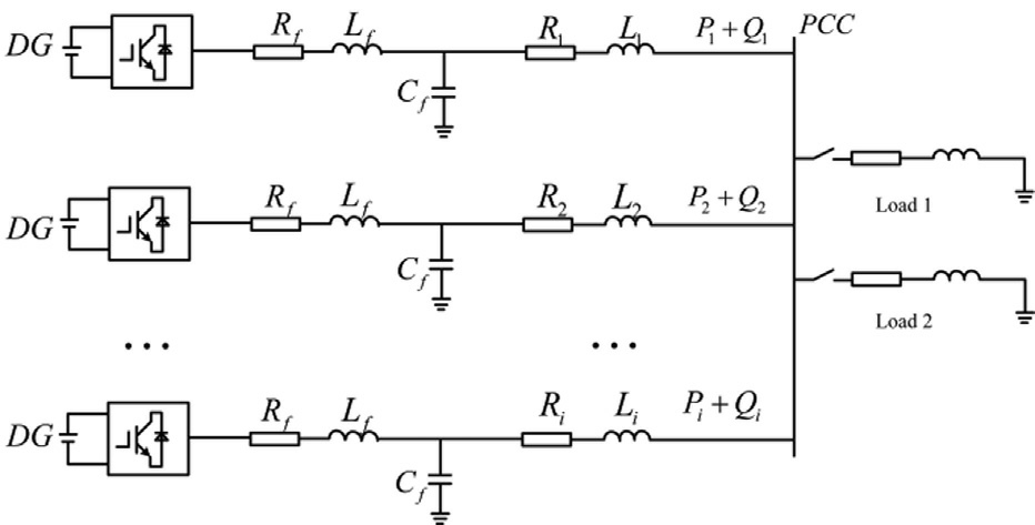
Fig.1.System structure diagram.
The expressions for the active power,P,and reactive power,Q,flowing from the grid-forming inverters to the PCC can be derived as follows:
where Ui denotes the amplitude of the output voltage of the i-th converter;VPCC denotes the voltage at the PC C;θi denotes the difference in the phase angle betwe en Ui and VPCC;Ri and Xi denote the resistance and inducti ve reactance of the output line at the i-th converter.P i and Qi denote the active power and reactive power,respe ctively,flowing from the i-th converter to the PCC.
In conventional droop control strategies,the line impedances are assumed to be purely inductive,i.e.,Ri 0.Given the small phase angle difference θi,the approximations,sin θiθi and cos θi1 hold.Consequently,Eqs.(1) and (2) can be simplified as follows:
Under inductive line impedance conditions (X  R),the active power was predominantly governed by the phase angle difference between the voltages at both ends of the line,as shown in Eqs.(3) and (4),whereas the reactive power is primarily determined by the voltage magnitude difference.This decoupled relationship forms the foundation of conventional droop-based grid-forming control strategies,which can be expressed as follows:
where ωi denotes the actual output voltage frequency of the i-th grid-forming inverter;ω0i and U0i denote the noload output frequency and no-load voltage magnitudeof the i-th inverter,respectively;kpi and kqidenote the acti ve power droop coefficient and reactive power droop coe ffi-cient. denotes the reactive power that converter i must output to achieve load sharing .
 denotes the acti ve power that converter i must output to achieve load sharing.
1.2 Impact of line impedance discrepancies on reactive power sharing
Fig.2 depicts the conventional droop control of reactive power droop characteristics.When the no-load voltage was set to U0i and parallel-connected converters employed identical droop coefficients,the line impedance mismatches caused deviations in their actual output voltages,forcing them to operate at distinct operating points,A1 and A2,presenting the voltage disparity,ΔU,and the reactive power deviation,ΔU,due to which the reacti ve power cannot be proportionally allocated among the converters.The DG outlet voltage can be obtained from Fig.2,as follows:
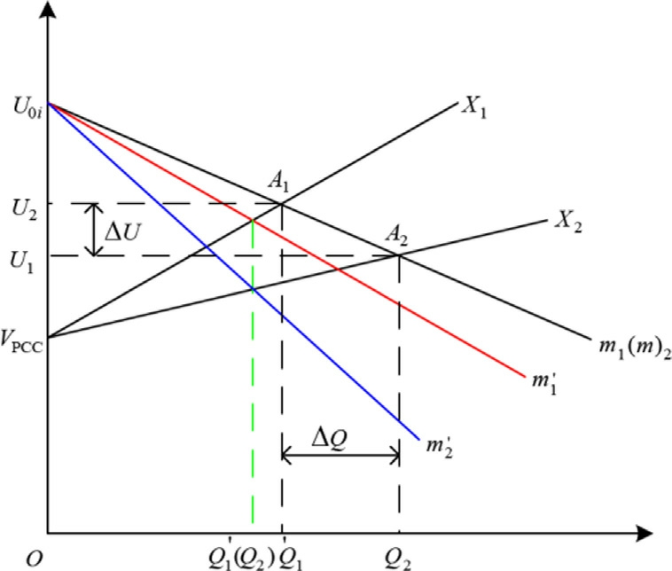
Fig.2.Dynamic droop control schematic diagram.
Assuming two converters with a rated capacity ratioof![]() to achieve proportional reactive power allocation according to their capacity ratio,the droop coefficients must satisfy the following relationship:
to achieve proportional reactive power allocation according to their capacity ratio,the droop coefficients must satisfy the following relationship:
where  denotes the reactive power that the i-th gri dforming converter must output to achieve proportional load sharing.When a voltage deviation exists between two parallel-connected converters,signi ficant reactive circulating currents are observed in the system,presenting reactive power sharing errors.The relative error canbe quantified as follows:
Because the reactive power in the syst em is conserved,there is:
By combining Eqs.(4),(6),and (7)–(9),the following relationship can be derived:
As established earlier,the conditions required to achieve proportional reactive power sharing among the parallel-connected converters with heterogeneous power ratings are as follows:
2 Dynamic droop control and adaptive virtual impedance design
2.1 Dynamic droop control
Conventional droop control can achieve power sharing ingrid-forming co nverters,but line impedance mismatches prevent precise proportional allocation.Fig.2 depicts the droop characteristic curves of distributed generation(DG) units with identical rated capacities and droop coefficients.Under ideal conditions,these units must satisfy proportional power sharing relationships.However,in practical operation,impedance mismatches among the feeders inevitably induce power allocation deviations.
Therefore,we proposed a power allocation strategy based on dynamic droop control in this study (see Fig.2).For uneven power allocation,the droop control curves m1 (m2)were dynamically adjusted to ![]() respectively.This adjustment modified the actual power outputs of each DG unit to
respectively.This adjustment modified the actual power outputs of each DG unit to ![]() thereby eliminating the power deviation,ΔQ,caused by impedance mismatches and enhancing the precision of power-sharing equilibrium ingrid-forming converter systems.Therefore,the Q-V droop control Eq.(6) is modified as follows:
thereby eliminating the power deviation,ΔQ,caused by impedance mismatches and enhancing the precision of power-sharing equilibrium ingrid-forming converter systems.Therefore,the Q-V droop control Eq.(6) is modified as follows:
where λidenotes the line impedance coefficient,representing the modification to the original droop control curve.Bysubstituting Eq.(14) into Eq.(4),the expression for the power allocated to the DG units under the impro ved droop control scheme can be derived as follows:
In the control architecture,the introduced term,λiQ,was established as a feed forward compensation mechani sm.By dynamically injecting a correction factor (λiQ)proportional to its own reactive power output,Q,into the voltage reference command,it actively emulated and canceled out the major portion of the reactive voltage drop generated by the current flowing through the line impeda nce,Xi.The line impedance coefficient,![]() must satisfy the following requirements:
must satisfy the following requirements:
The coefficient,λi,is directly involved in the calculation of the control law,and its value directly affects the system stability,voltage stability,and control accuracy.Therefore,the constraints on λiinclude: small-signal stability constraint,voltage deviation constraint,and sensitivity constraint.
The small-signal stability constraint ensures that after introducing λi for compensation,the damping characteristics of the system were not damaged and power oscillations were avoided.The constraint conditions are as follows:
where SF denotes the stability margin safety factor(typically >1.5),which is determined by the requirements for the phase margin or minimum damping ratio.
The voltage deviation constraint ensures that the compensated inverter output voltage does not deviate excessively from its rated value owing to over-adjustment,thereby ensuring the proper operation of the local loads and compliance with grid codes.The constraint condition isdefined as follows:
where Qmax denotes the maximum reactive power that the converter can supply and ΔVmax denotes the maximum allowable voltage deviation.
The sensitivity constraint ensures that the value of λi is sufficiently large to effectively offset the impact of the line impedance mismatches and achieve accurate reactive power distribution.The constraint conditions are as follows:
where ΔZmax denotes the maximum line impedance mism atch between the output of each converter and the PCC.
Conventional droop control inherently exhibits steadystate power sharing errors owing to its static error characteristic.We introduced an adaptive virtual impedance compensation scheme to address this limitation by enhancing the power allocation accuracy.
2.2 Adaptive virtual impedance design
Conventional droop control is implemented based on the assumption of purely inductive impedance for the Pω/Q-U decoupling.However,the low-voltage grid lines exhibit a resistive-inductive impedance,leading to severe power coupling.We introduced virtual impedance to reconstruct the system output impedance and employed anadaptive virtual resistance compensation method to dynamically adjust the equivalent impedance.Thus,the dynamic droop control was optimized.This approach enables precise reactive power allocation based on the droop coefficients while effectively reducing the power deviations.Fig.3 depicts a block diagram of the system control architecture.
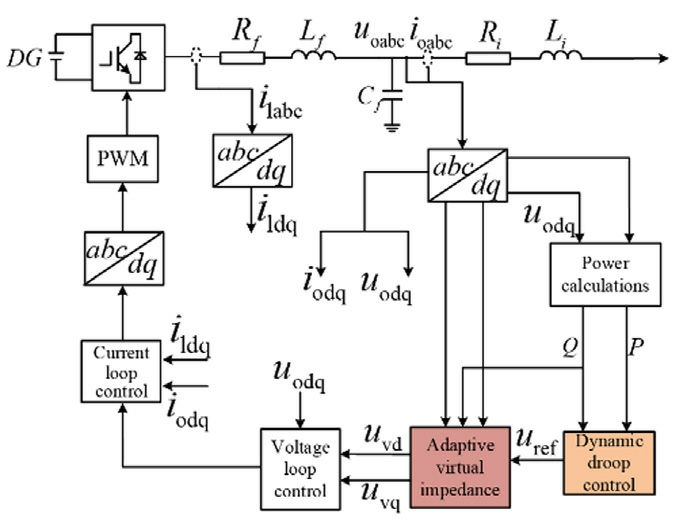
Fig.3.Block diagram of system control.
The total impedance of a multi-parallel converter system comprises both the equivalent output impedanceof the individual converters,along with the line impedance.To achieve power decoupling control and adaptive virtual impedance regulation,we designed a virtual impedance comprising constant inductance and adaptive inductance.Constant inducta nce was implemented to optimize the power decoupling;the adaptive inductance was dynamically adjusted based on the line impedance to achieve impedance matching between the parallel converters and enhance the flexibility of system control.
We designed a virtual impedance controller (incorporating adaptive virtual inductance Xvi)to achieve active/re -active power decoupling when droop control was employed for grid-forming inverters.The inductance coefficient was dynamically adjusted based on variations in the reactive power and voltage,thereby enhancing the system dynamic response capability and adaptability to impedance matching.The technical implementation details are as follows:
where δi denotes the adaptive virtual impedance coe ffi-cient,and serves as a time-varying gain.It optimizes reactive power distribution by dynamically adjusting the amplitude or phase of the converter’s output voltage.This coefficient presents a trade-off with the system stability.Increasing δi enhances the capability to compensate for impedance mismatch,suppresses the circulating currents,and improves the power sharing accuracy.However,an excessively large δi reduces system damping,which may cause oscillations or even instability.Conversely,although decreasing δi im proves the stability,it reduces the compe nsation effectiveness.
By applying the aforementioned adaptive virtual inductance method,the virtual inductance for each converter,is designed as follows:![]()
where Xvdenotes the virtual inductance that ensures the equivalent line impedance remains resisti ve;Xvidenote s the adaptive virtual inductance;and Xvridenotes the total virtual inductance for each DG unit.
Based on the above equations,the relative active power output error, ,of parameter DG1 after incorporating adapti ve virtual impedance can be calculated as follows:
The output voltage corresponding to the proposed adaptive virtual inductance when represented in the dq coordinate system,can be expressed as follows:
where urefd and urefq denote the d and q-axis component s,respectively,of the converter’s output voltage reference value,uref ;ioq and iod denote the d and q-axis components of the line current,respectively.
3 Parameter identification based on transformer
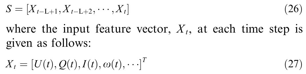
As a deep learning architecture based on the selfattention mechanism,the transformer neural network exhibits high efficiency in sequential and temporal data modeling.Conventional recurrent neural networks(RNNs) and long short-term memory (LSTM) models suffer from slower information propagation when processing long sequences owing to their sequential computational nature.Conversely,the transformer architecture addresses this limitation by leveraging self-attention mechanisms to directly capture the dependencies between arbitrary positions in sequences,thereby overcoming the constraints of recurrent computations.The proposed model primarily employs an encoder-decoder architecture.Each encoder block comprises a positional encoding layer,a multihead attention layer,an Add&Norm layer,and a feedforward network layer.Fig.4 depicts the transformer neural netw ork structure.control coefficients (kp,kq)and adaptive virtual impedance coefficient (δi)for grid-forming converters.Thus,we constructed an end-to-end temporal-to-parametric mapping model.The input is a multivariate time series,S,of length,L(determined by the dominant dynamic time constant,typically 500–2000 points) with a specific sampling rate(aligned with the control frequency,approximately 10–20kHz),defined as follows:
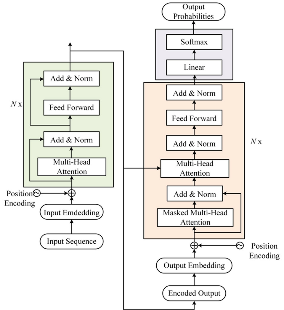
Fig.4.The network structure of the transformer.
We applied this structure to identify the dynamic droop
To eliminate the discrepancies in dimensions and numerical ranges among different physical quantities,the sequence is fed into the transformer neural network following mean–variance normalization.The normalization method is calculated as follows:
μxdenotes the meanvalue of this feature computed over the entire training set.
σx denotes the standard deviation of this feature computed over the entire training set.
The transformer model employs sinusoidal positional encoding to inject the sequ ential ordering information.It iscalculated as follows:
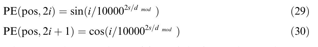
where pos denotes the position of the input data,i denotes the dimension,d modrepresents the number of input features,and pidenotes the positional encoding.
The core principle behind leveraging transformer neural networks for dynamic coefficient identification involves utilizing multi-head self-attention mechanisms to achieve the collaborative extraction of multi-dimensional dynamic features and decision optimization in control systems.The operation of the self-attention mechanism of the network isas follows.First,the input matrix,S,is transformed into matrix S1 through positional encoding.Subsequently,we defined the query matrix, Q,key matrix, K,and value matrix, V,which correspond to the hidden state matrices obtained by multiplying S1 with the query weight matrix WQ,key weight matrix W K,and value weight matrixW V,respectively.The detailed calculation formulas are given as follows:
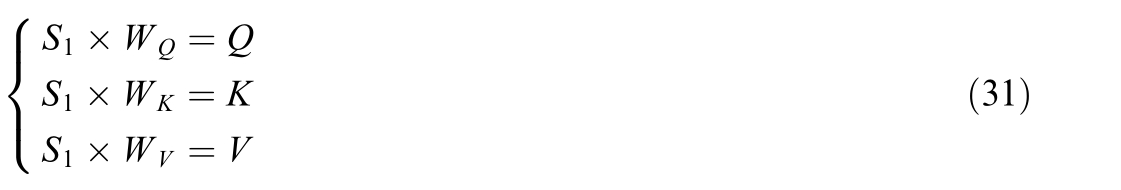
Eq.(31) performs three distinct linear transformations on the same input matrix,S1,to represent its three different states.After obtaining matrices,Q,K,and V via computation,the scaled dot-product attention is further calculated asfollows:
where Attention (·) denotes the scaled dot-product attention function;KT denotes the transpose of matrix K;and dk denotes the number of columns in matrices Q and K,i.e.,the vector dimension.
We applied multi-head attention mechanism (depicted inFig.5) for the input matrices,Q,K,and V,to obtain![]() where h denotes the number of attention heads.This mechanism projects the data into multiple subspaces in parallel.Some of the attention heads focus on voltage fluctuations and harmonic distortion characteristics,corresponding to the virtual impedance adjustment strategy that suppresses oscillations in history.Another set of heads analyzes the frequency deviation trend,dynamically generating a correction amount for the droop coefficient,kp,to accelerate the frequency recovery.The remaining heads monitor the power distribution balance and historical fault patterns,thereby coordinating the adjustment of kq and avoiding parameter conflicts.The formula for this process is given as follows:
where h denotes the number of attention heads.This mechanism projects the data into multiple subspaces in parallel.Some of the attention heads focus on voltage fluctuations and harmonic distortion characteristics,corresponding to the virtual impedance adjustment strategy that suppresses oscillations in history.Another set of heads analyzes the frequency deviation trend,dynamically generating a correction amount for the droop coefficient,kp,to accelerate the frequency recovery.The remaining heads monitor the power distribution balance and historical fault patterns,thereby coordinating the adjustment of kq and avoiding parameter conflicts.The formula for this process is given as follows:
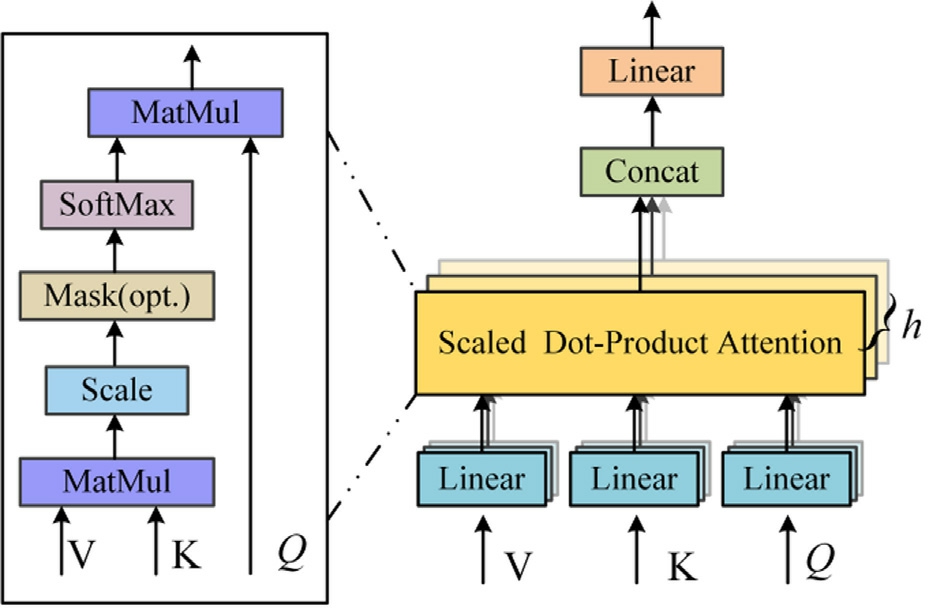
Fig.5.Multi-head self-attention diagram.
where MultiHeadAtt (·) denotes the multi-head attention function and Concat (·) denotes the function for concatenating attention matrices.
Each attention layer is followed by a feed-forward network (FFN),which typically con sists of two linear layers and a ReLU activation function:
We obtain the final sequence representation,![]() ,after processing through N encoder layers .Global Average Pooling (GAP) is typically applied to compress the sequence into a fixed-length vector
,after processing through N encoder layers .Global Average Pooling (GAP) is typically applied to compress the sequence into a fixed-length vector![]()
Lastly,the control parameters are output through a simp le linear regression layer.
We adopted an asymmetric processing architecture to satisfy the requirement of an ultra-fast control cycle(<100 μs).The transformer is operated asynchronously at a lower frequency (millisecond level),and its outputs function as parameter commands acting on the highspeed (microsecond level) underlying dual-loop voltage and current controller.The training data are obtained from high-fidelity simulations encompassing various disturbance scenarios,with optimal parameter labels for each dynamic scenario generated through offline optimization.
4 Example simulation
To validate the effectiveness and superiority of the proposed control strategy,we conducted HIL simulations on three parallel-connected grid-forming converters.We implemented the circuit architecture,which comprisesa parallel system of three grid-forming converters,in the StarSim HIL platform for testing.
In this experiment,a real-time simulator equipped with a multi-core CPU and an FPGA forms the core of the hardware configuration of the StarSim HIL platform.The CPU runs the grid and load models,whereas the FPGA operates the detailed models of three parallel grid-forming converters at a high speed witha nanosecond-level step size.The simulator transmits three-phase voltage and current signals to three real converter controllers via a high-precision analog output board.It receives the PWM pulse signals returned by the controllers through a digital input board,thereby forming a closed loop.In the data acquisition workflow,the host computer trans mits all the key variables (such as the reactive power of each converter, Q1, Q2, Q3) in real time via ethernet in a streaming manner.This helps in monitoring and analyzing the distribution performance.To enable integrated communication with the real world,the communication board built into the simulator(supporting protocols such as CAN) emulates the upper-level energy management system.Thus,reactive power dispatching commands are transmitted to the controller to test its coordination and response capabilities under real power grid conditions.Fig.6 depicts the exp erimental setup.Table 1 summarizes the system parameters.
Table 1 System data.
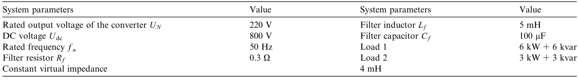
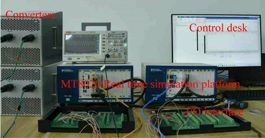
Fig.6.Experimental platform.
Two distinct operational scenarios were established to demonstrate the superiority of the proposed control strategy.Condition 1 has a converter rated power ratioof 1:1:1,whereas Condition 2 has a converter rated power ratio of 3:2:1.Table 2 summarizes the parameters for the two operational scenarios.
Table 2 Line impedance.
Comparative evaluations were conducted against both conventional droop control and the ad aptive droop control method presented in Ref.[11]to demonstrate the superiority of the proposed control strategy.
4.1 Working condition 1
In this calculation example,we used three control methods for comparison to verify the power distribution and volta ge drop of the converters under a rated capacity ratio of 1:1:1 and sudden load changes.Figs.7–9 depict the simulation results.
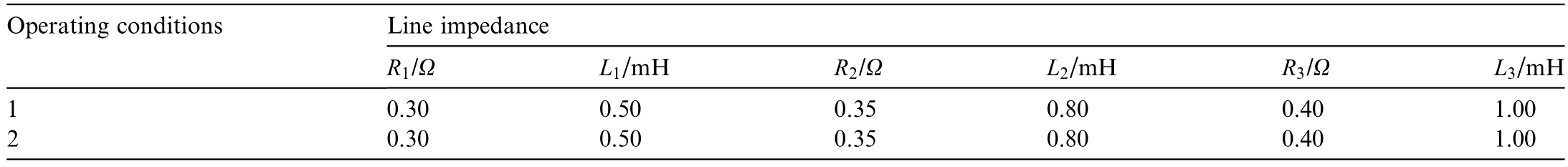
The system frequency remains synchronized under steady-state conditions,enabling active power to be evenly shared.However,reactive power cannot be allocated proportionally corresponding to their rated capacities owing tomismatches between the output line impedances of individual converters.Under conventional droop control,the DGs failed to proportionally share the load power corresponding to their rated capacities owing to line impedance mismatch,with the relative power sharing deviation peaking at 21%,as shown in Fig.7(b).Furthermore,the maximum relative deviation further increased to 24.6%following the activation of Load 2.
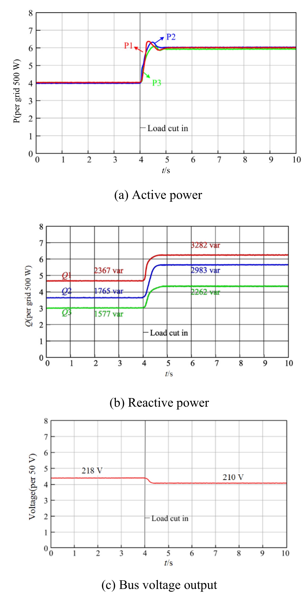
Fig.7.Simulation results under traditional droop control.
Fig.8 depicts the power sharing performance of the individual DGs under the proposed dynamic droop control strategy.The proposed control strategy a chieves the proportional load power sharing among the DGs based ontheir rated capacities,as shown in Fig.8(b).DG1,DG2,and DG3 deliver power in an approximate ratio of 1:1:1,with the individual unit deviations confined to 1.2–4.9%.The relative power sharing deviations are significantly reduced,thereby achieving precise proportional power allocation.
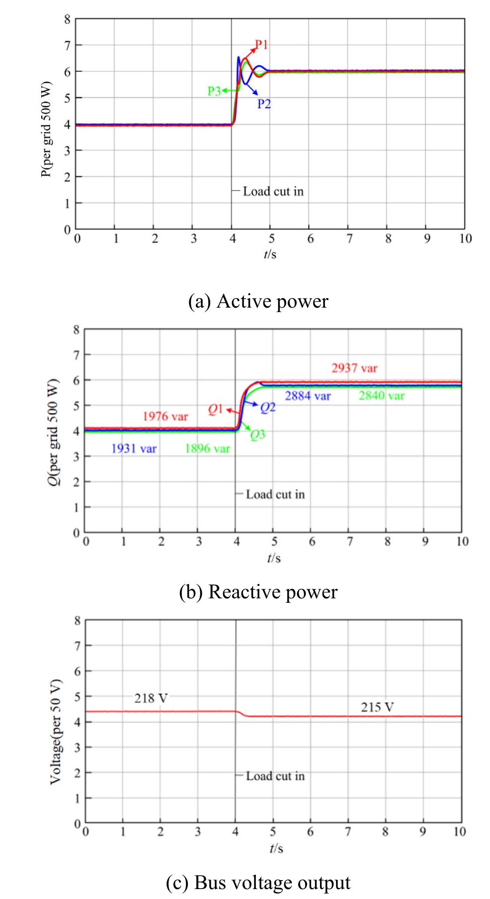
Fig.8.Simulation results under the control proposed in this paper.
Fig.9 depicts the DG power sharing performance under the adaptive droop control strategy proposed in Ref.[11],with error margins ranging from 3.5% to 10.2%.After Load 2 was connected and the system reached steadystate operation,the error margins were further adjusted to4.2–9.8%.The load sharing accuracy was improved under the adaptive control proposed in Ref.[11]when compared with the conventional droop control strategies.However,to completely eliminate the power allocation errors,the output impedance of the converters must be precisely matched to the line impedance.
Fig.9.Simulation results from Ref.[11].
Therefore,the proposed control strategy achieves enhanced reactive power sharing accuracy in the system while significantly reducing the magnitude of the output voltage deviations.
4.2 Working condition 2
Under the proposed control strategy,we effectively validated the power sharing performance of the converters with a rated capacity ratio of 3:2:1,as shown in Fig.10.
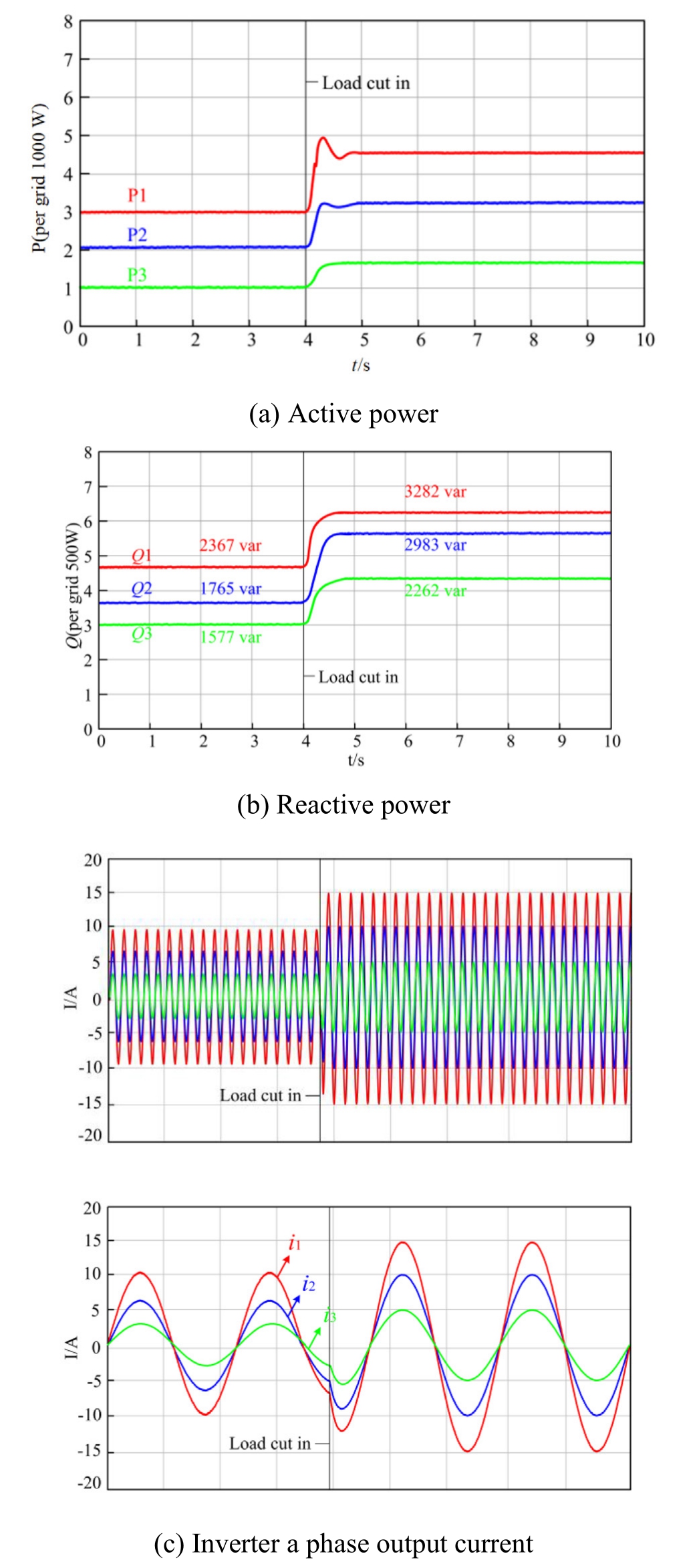
Fig.10.Simulation results for working condition 2.
The simulation results indicated that the converters consistently maintain an approximate 3:2:1 ratio in terms ofboth reactive/active power allocation and output current distribution under all the operational conditions.It can be clearly observed that the proposed control strategy isequally applicable to reactive power sharing among converters with different rated power capacities.
4.3Validation of disturbance rejection performance in weak grid scenarios
To validate the effectiveness of the proposed strategy under weak grid conditions,the short-circuit ratio (SCR) of the system was reduced to 2.5,which represents an extremely weak grid scenario.The system parameters were based on Table 1 and Case 1 in Table 2,with the three converters maintaining a rated capacity ratio of 1:1:1.The results are shown in Fig.11.
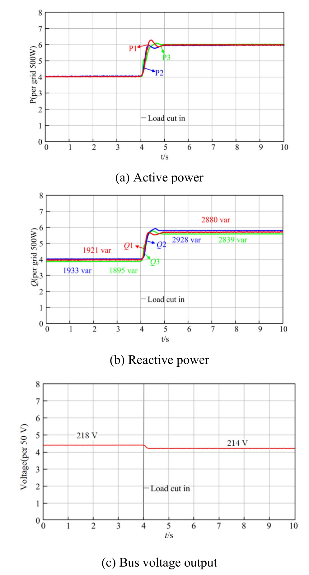
Fig.11.Validation of disturbance rejection performance in weak grid conditions.
Under weak grid conditions with an SCR of 2.5,the proposed control strategy can simultaneously achieve high-precision reactive power sharing and maintain excellent voltage stability when subjected to reactive load step disturbances,thereby validating the effectiveness of the proposed method in weak grid environments.
4.4 Training and validation of the transformer model
To evaluate the performance of the proposed transformer-based model,we generated a dataset containing 50,000 samples using an EMT model of three parallel grid-forming converters built on the StarSim HIL platform.Each sample comprises seven input features and two output targets (δi and kqi).The dataset was divide d into a training set (70%),a validation set (15%),and a test set (15%).The model was trained for 100 epochs using the Adam optimizer with a learning rate of 0.001 and a batch size of 64,employing the mean squared error(MSE)as the loss function.
Both the curves exhibit rapid convergence during the initial phase and gradually stabilize in the later stage,as shown in Fig.12.The validation curve closely tracks the training curve without complete overlap,thereby demonstrating effective generalization capability and the absence of overfitting.
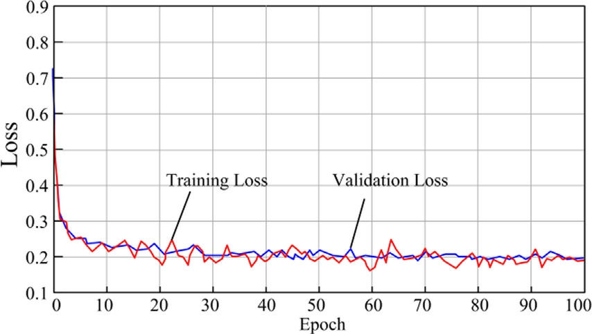
Fig.12.Training and validation loss curves.
On the independent test set,the model achieved low prediction errors for both δi and kqi .Table 3 summarizes the quantitative results,which demonstrate that the transformer can accurately model the intrinsic operational principles of grid-forming converters.
Table 3 Quantitative MAE results.
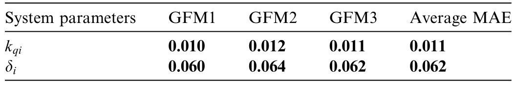
The results indicate that the proposed control model effectively identifies the correlation between the input features and operational parameters of grid-forming converters.Therefore,it achieves stable convergence during the training process while exhibiting reliable predictive performance on unseen data.
4.5 Simulation and analysis of adaptive virtual impedance
To verify the effectiveness of the adaptive virtual impedance strategy,three droop converters were connected in parallel to simulate the difference in connection impedance.Table 2 summarizes the actual line inducta nce parameters,and Fig.13 depicts the corresponding simulation results.
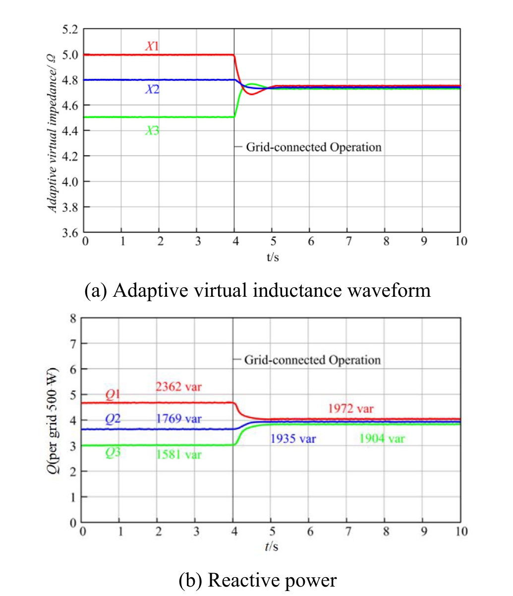
Fig.13.Adaptive virtual impedance simulation results.
The simulation results indicate that the adaptive virtual inductance identification algorithm based on the transformer neural network can accurately track the optimal virtual inductance parameters.It can effectively suppress the circulating currents between the converters,significantly enhance reactive power sharing accuracy,and achieve smooth transitions during device switching operations by dynamically compensating for the line impedance mismatches.
5 Conclusion
In this study,we proposed a collaborative reactive power control method that integrates adaptive virtual impedance compensation with dynamic droop regulation.The proposed method helps in overcoming the issueof uneven reactive power sharing caused by line impedance mismatches in multiple parallel grid-forming converters.The transformer neural network dynamically identifeis the virtual impedance and droop coefficients,thereby effectively suppressing the steady-state errors in droop control under impedance mismatch conditions.The simulation resul ts obtained from the StarSim HIL platform indicate that the proposed control method effectively suppresses the circulating power currents and significantly enhances the reactive power sharing accuracy.Furthermore,it precisely shares the power corresponding to the capacity ratios of the converters during load fluctuations while maintaining the AC bus voltage at the preset nominal value,exhibiting superior dynamic performance.
Transformer neural networks present considerable potential in modeling complex system dynamics,their application inpower electronics control is limited by their dependence onhigh-precision sensor data and substantial computational resources.Therefore,it presents considerable challenges to real-time performance and reliability.Future works must further investigate the adaptability of the control algorithm under complex grid environments,including highpenetration renewable energy integration and asymmetric fault conditions.Additionally,they must focus on enhancing itsdisturbance rejection capability,thereby optimizing the transformer network architecture to reduce the computational complexity,and facilitating its real-time implementation in power electronic controllers.
CRediT authorship contribution statement
Lizhen Wu: Writing– review &editing,Visualization,Methodology.Yunpeng Bao: Writing– original draft,Visualization,Data curation.Long Xian: Writing– review&editing,Software,Data curation. Nan Qiu: Data curation. Wei Chen: Writing– review &editing.
Declaration of competing interest
The authors declare that they have no known competing financial interests or personal relationships that could have appeared to influence the work reported in this paper.
Acknowledgments
This work was supported by the National Natural Science Foundation of China (No.62063016),and the Science and Technology Plan of Gansu Province (No.25JRRA088).
References
[1]Z.Liu,J.Meng,J.Zhang,et al.,Research on the development model ofnew energy bases based on the electricity-hydrogen-carbon synergy,J.Glob.Energy Interconnect.7(5)(2024)473–491.
[2]L.Zhang,Q.Liu,X.Zhao,et al.,Research on renewable energy penetration in wind and solar resource-i ntensive areas from the perspective of power demand growth and load flexibility enhancement,J.Glob.Energy Interconnect.7 (5) (2024) 454–462.
[3]Y.Ma,R.Fang,L.Miao,et al.,Analysis of the operation status and countermeasures analysis of China’s carbon market,J.Glob.Energy Interconnect.7 (6) (2024) 675–683.
[4]X.Huang,F.Xu,C.Lu,et al.,Optimal configuration of AC filter for 24-pulse diode rectifier unit based offshore wind power integration System,J.Glob.Energy Interconnect.7(5)(2024)550–557.
[5]A.R.Cabero,J.R.Perez,M.Prodanovic,Virtual impedance design considerations for virtual synchronous machines in weak grids,IEEE Trans.Power Electron.8 (2) (2020) 1477–1489.
[6]B.K.Poolla,D.Groß,F.Dörfler,Placement and implementation of grid-forming and grid-following virtual inertia and fast frequency response,IEEE Trans.Power Syst.34(4)(2019)3035–3046.
[7]Z.Liu,Y.Sun,C.Ma,An overview of grid-forming technology and its application in new-type power system,Global Energy Interconnect.7 (5) (2024) 541–552.
[8]S.Tan,J.C.Vasquez,J.M.Guerrero,Attack-resilient control for converter-based DC microgrids,Global Energy Interconnect.6(6)(2023) 751–757.
[9]Y.Hu,J.Xiang,Y.Peng,et al.,Decentralised control for reactive power sharing using adaptive virtual impedance,IET Gen.Transmiss.Distrib.12 (5) (2018) 1198–1205.
[10]B.Pawar,E.I.Batzelis,S.Chakrabarti,et al.,Grid-forming control forsolar PV systems with power reserves,IEEE Trans.Sustainable Energy 12 (4) (2021) 1947–1959.
[11]J.Chen,M.Liu,X.Chen,et al.,Wireless parallel and circulation current reduction of droop-controlled inverters,Trans.China Electrotech.Soc.33 (7) (2018) 1450–1460.
[12]Y.Du,X.Lu,H.Tu,et al.,Dynamic microgrids with self-organized grid-forming inverters in unbalanced distribution feeders,IEEE J.Emerg.Sel.Top.Power Electron.8(2)(2019)1097–1107.
[13]Y.Mi,H.Cai,Y.Song,et al.,Study on reactive power sharing of island microgrid based on synchronous compensation,Trans.China Electrotech.Soc.43 (9) (2019) 1934–1943.
[14]Q.Liu,W.Huang,Z.Guo,et al.,Reactive power sharing strategy formultiple parallel grid-forming converters based on adaptive virtual impedance,Power Syst.Autom.48 (15) (2024) 122–130.
[15]H.Zhang,S.Kim,Q.Sun,etal.,Distributedadaptive virtualimpedance control for accurate reactive power sharing based on consensus control inmicrogrids,IEEE Trans.Smart Grid 8 (4) (2017)1749–1761.
[16]J.Zhou,S.Kim,H.Zhang,et al.,Consensus-based distributed control for accurate reactive,harmonic and imbalance power sharing inmicrogrids,IEEE Trans.Smart Grid 9 (4) (2018)2453–2467.
[17]D.K.Dheer,Y.Gupta,S.Doolla,A self-adjusting droop control strategy to improve reactive power sharing in islanded microgrid,IEEE Trans.Sustainable Energy 11 (3) (2019) 1624–1635.
[18]Q.Xie,R.Wang,K.Lin,Droop control strategy of parallel inverters based on port voltage integration and variable droop coefficient,Trans.China Electrotech.Soc.38(6)(2023)1596–1607.
[19]N.Mohammed,A.Lashab,M.Ciobotaru,et al.,Accurate reactive power sharing strategy for droop-based islanded AC microgrids,IEEE Trans.Ind.Electron.70 (3) (2022) 2696–2707.
[20]Y.Fu,Z.Zhang,Y.Mi,et al.,Droop control for DC multi-microgrids based on local adaptive fuzzy approach and global power allocation correction,IEEE Trans.Smart Grid 10 (5) (2018)5468–5478.
[21]C.Dou,Z.Zhang,D.Yue,et al.,Improved droop control based on virtual impedance and virtual power source in low-voltage microgrid,IET Gen.Transmiss.Distrib.11 (4) (2017) 1046–1054.
[22]H.Sellamna,A.M.Pavan,A.Mellit,et al.,An iterative adaptive virtual impedance loop for reactive power sharing in islanded meshed microgrids,Sustainable Energy Grids Netw.24 (2020)100395.
[23]X.Chen,H.Jia,S.Chen,et al.,Improved droop control strategy based on line impedance identification for reactive power sharing in microgrid,High Volt.Eng.43 (4) (2017) 1271–1279.
[24]X.Liang,C.Andalib-Bin-Karim,W.Li,et al.,Adaptive virtual impedance-based reactive power sharing in virtual synchronous generator controlled microgrids,IEEE Trans.Ind.Appl.57 (1)(2020) 46–60.
[25]R.Moslemi,J.Mohammadpour,Accurate reactive power control ofautonomous microgrids using an adaptive virtual inductance loop,Electr.Pow.Syst.Res.129 (2015) 142–149.
[26]B.Fan,Q.Li,W.Wang,et al.,A novel droop control strategy of reactive power sharing based on adaptive virtual impedance in microgrids,IEEE Trans.Ind.Electron.69(11)(2021)11335–11347.
[27]Y.Wang,J.Tang,J.Zhao,Power quality optimization strategy in islanded microgrid based on adaptive virtual impedance control,Autom.Electr.Power Syst.47 (7) (2023) 63–73.
[28]Y.Gupta,N.Parganiha,A.K.Rathore,et al.,An improved reactive power sharing method for an islanded microgrid,IEEE Trans.Ind.Appl.57 (3) (2021) 2954–2963.
[29]Z.Wang,D.Timlin,X.Gong,et al.,TDR-transformer: a transformer neural network model to determine soil relative permittivity variations along a time domain reflectometry sensor waveguide,Comput.Electron.Agric.237 (2025) 110730.
Received 27 May 2025;revised 25 September 2025;accepted 15 October 2025
Peer review under the responsibility of Global Energy Interconnection Group Co.Ltd.
* Corresponding author.
E-mail addresses: wulzlut@163.com (L.Wu),2603230153@qq.c om(Y.Bao),806663958@qq.com (L.Xian),853905737@qq.com (N.Qiu),1341814827@qq.com (W.Chen).
https://doi.org/10.1016/j.gloei.2025.10.004
2096-5117/© 2025 Global Energy Interconnection Group Co.Ltd.Publishing services by Elsevier B.V.on behalf of KeAi Communications Co.Ltd.This is an open access article under the CC BY-NC-ND license(http://creativecommons.org/licenses/by-nc-nd/4.0/).

Lizhen Wu received the M.S.degree in the control theory and control engineering from Lanzhou University of Technology,Gansu,China,in 2004,and the Ph.D.degree in control theory and control engineering from Lanzhou University of Technology in 2017,respectively.She is studying in power system and its automation in National Active Distribution Network Technology Research Center,Beijing Jiaotong University,Beijing,China,in 2015.Currently,she is an Associate Professor/Master Supervisor at College of Electrical and Information Engineering Lanzhou University of Technology,she is a Professor/Doctoral Supervisor at College of Electrical and Information Engineering Lanzhou University of Technology,where she teaches courses on power electronics,control theory and renewable energy systems.Her interests include distributed generation and Microgrids;Micro-energy grid coordination control;Power quality control;Artificial intelligence and data-driven theory for smart grid;Networked control theory and its application.