0 Introduction
With the large-scale development of renewable energy[1], an increasing number of high-capacity, long-distance high-voltage direct current (HVDC) power transmission projects have been implemented [2].For some loadconcentrated areas, there are multiple DC-intensive feeds.For example, in China, the western region is not well developed, but is rich in energy resources, whereas the eastern region is the load center located thousands of kilometers away[3].To realize‘‘west-east power transmission”and make full use of renewable resources,China has developed large-scale DC power transmission projects based on line commutate converters (LCC) [4].Therefore,Central and Eastern China have developed a multi-DC infeed system [5].Several problems in system operation and control are caused by multi-DC intensive feeding,such as multiple DC commutation failures and AC-DC chain failure [6-9].Strengthening the receiver grid and expanding the AC scale are effective methods to solve the above problems [10], but it is difficult to change the grid structure or increase the traditional power supply capacity significantly because of practical factors such as geographical conditions and natural resources in the receiver region.
Using voltage source converters (VSCs) is a feasible solution to solve the problems of multi-DC-infeed receiving power networks to realize regional interconnection of receiving power networks.Within existing major regional power grids, the structure of the grid is complex and closely connected.In China, the UHV 1000-kV channel between Henan, Hubei, and Hunan plays an important role in power transmission, voltage support, and power flow evacuation.It is difficult to disconnect the interprovincial connections by completely segmenting and dividing the Central China grid into several asynchronous interconnected sub-partitions.Therefore, it is more reasonable to retain an incomplete segmentation of communication links.The Southern Power Grid of China adopts an VSC-HVDC to realize incomplete segmentation of the Guangzhou power grid [11].
Many comprehensive studies have been conducted on receiving-system scenarios with VSC inputs.To measure the strength of a hybrid dual-infeed system, Reference[12] proposed an impedance-based effective short-circuit ratio, and Reference [13] proposed a hybrid multi-infeed effective short-circuit ratio to quantify the impact of the VSC on the system.References [14-16] proposed hybrid dual-infeed systems equivalent to a single-infeed LCCHVDC system to analyze the interaction between VSCs and LCCs.Reference [17] used the Spearman correlation coefficient to analyze the impact of VSC on four types of stability.References [18,19] focused on the VSC and proposed different strategies to improve its power characteristics.However, these studies did not consider the scenario of segmenting and analyzing the interaction between LCCs.Reference [20] proposed a method to determine the location of a VSC in a segmented system;however,this study did not analyze the impact of the VSC.In References[21,22], research was conducted to improve the frequency stability through the control of the VSC in complete segmentation.However, neither study considered the voltage support ability and incomplete segmentation.
Under incomplete and complete segmentations,the system characteristics are completely different from those of the running state and function of the VSC.In complete segmentation,there is no AC connection between the partitions, and the VSC acts as an important power flow channel to realize power exchange between the two partitions.Simultaneously,owing to the distribution of the traditional power supply, the VSC must also provide inertia support to maintain the frequency stability of the receiving system.In incomplete segmentation,AC channels exist on both sides of the partition.Therefore, there are fewer problems with power flow and frequency.However,owing to the existence of an AC connection, the multiple LCCHVDCs at the receiving system maintain a certain coupling, which results in commutation failure in the fault;therefore, research on incomplete segmentation needs to focus on reducing the AC connection between different LCC-HVDCs and improving the anti-interference capability.Therefore, in incomplete segmentation, the voltage support capability of the VSC must be the primary research topic.Because of the different research emphases and analysis objectives of the two segmentation methods,it is necessary to adopt different methods to analyze the role of VSC in them.
Some studies have suggested that impedance-equivalent asynchronous devices can be used to analyze the strength of a system containing an asynchronous power supply,and further analysis can be conducted.Owing to the nonlinearity of the VSC, it exhibits different port characteristics under different operating conditions.Therefore, the incremental model can be used to equate the VSC in different states to the impedance,which can be connected to the AC system for unified analysis.However, in a completely segmented system, the micro-incremental models of the two segmented systems cannot be simultaneous, because there is no communication connection; therefore, this method is not suitable for completely segmented systems.
To quantify the impact of a VSC segmented in a multi-DC-infeed system, a micro-incremental model of the power system is established based on the power characteristics of the VSC and transmission line.The VSC can be considered as equivalent to an impedance; then, the multi-infeed short circuit ratio (MISCR) and multiinfeed interaction factor(MIIF)can be calculated to quantify the support of the VSC and the effect of reducing the coupling of LCCs.An example analysis is conducted, and the accuracy of the micro increment model and the corresponding index is verified.
1 Incompletely segmented system based on VSC
1.1 Topology of incompletely segmented MISCR system considering the influence of VSC
The original AC transmission line should be disconnected and replaced to segment the multi-infeed DC system based on the VSC.The topology of an incompletely segmented system is shown in Fig.1.
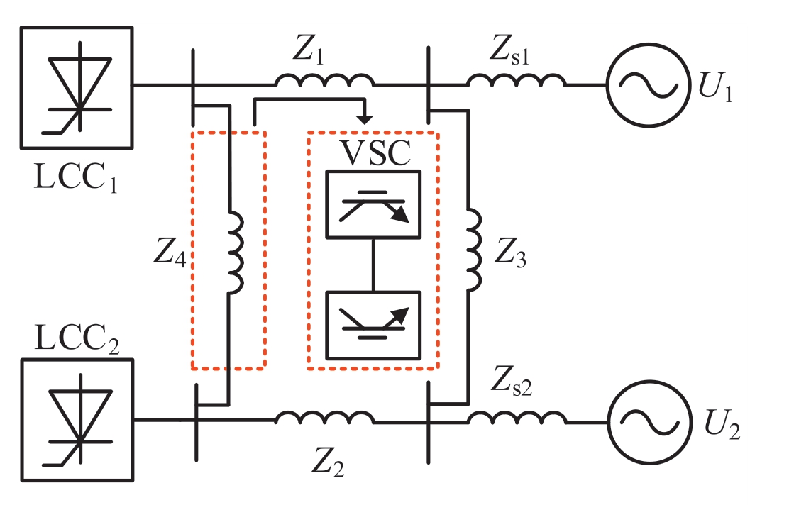
Fig.1.Topology of incompletely segmented system based on VSCHVDC.
The topology of the completely segmented system is shown in Fig.2.In a completely segmented system, no alternative current connection exists between the LCCs,and they are connected by a VSC-HVDC.
In Fig.1 and 2, U1 and U2 are the equivalent voltages of the AC system, Zs1 and Zs2 are the equivalent impedances of the system, and Z1 - Z4 are the impedances of the other AC lines.LCC1 and LCC2 are line-commutate converter HVDCs.
The AC system was segmented into two partitions by the VSC and AC lines, each carrying one LCC-HVDC.As shown in Fig.1, the receiving system is incompletely segmented by the VSC near the two DC infeed buses.Therefore,the AC side has both DC and AC connections.If line Z3 is removed with incomplete segmentation, the system becomes a completely segmented system in which the two LCCs have no AC connection.A comparison of the different segmenting methods is presented in Section 3.2.
In a real power grid,the connections between buses and branches are complicated, and many factors must be considered during segmentation.Studies have been conducted on the regional segmentation of complex power grids based on local fitness measures from the perspectives of system topology and electrical relations [23].For the convenience of analysis,it is assumed that the system in Fig.1 was segmented based on the segmentation algorithm.The AC system represented by LCC1 and U1 is divided into the same partition, the AC system represented by LCC2 and U2 is divided into another partition,and the two partitions are connected by the VSC and the lines between buses 1 and 2.
1.2 MISCR considering the influence of VSC
The CIGRE working group proposed the MISCR to characterize the strength of the multi-infeed DC system.The calculation is as follows:
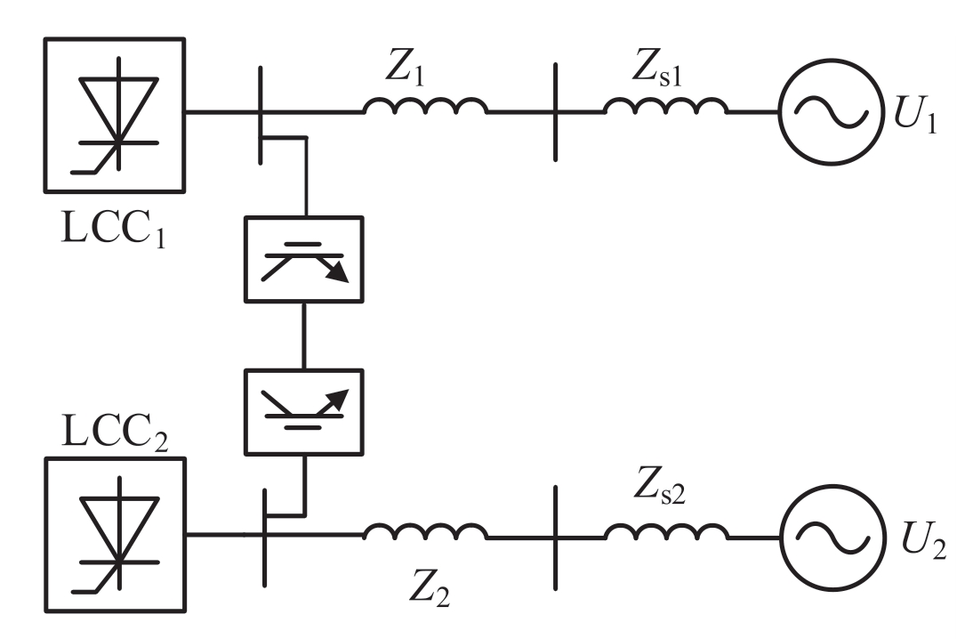
Fig.2.Topology of completely segmented system.
where Pdi and Pdj are the powers of LCCs i and j, respectively, and MIIFji is the MIIF of the two LCCs.
According to the CIGRE working group definition of MIIF, three reactors are placed in the converter bus node j, so that the voltage of node j is reduced by 1 %, and the voltage of node i is reduced by ΔUi.The ratio of the two is the MIIF, given as follows [24]:
The MIIF is often used to describe the degree of electrical coupling in DC.For a brief calculation of the MIIF,the impedance matrix element ratio method can be used,as given by:
where Zji and Zjj are the elements of row j in column i and row j in column j of the impedance matrix of the AC system, respectively.
When the system is segmented based on the VSC, the MIIF calculation method shown in (2) is affected by the VSC and needs to be adjusted.Here, the VSC does not affect the power of the LCC transport; therefore Pdi, Pdj remain unchanged.The VSC has a voltage support effect on the MIIF and short-circuit capacity.
Therefore, after VSC segmentation, the MISCR of the system becomes:
where S′ac is the short-circuit capacity after segmenting and MIIF′ji is the MIIF considering VSC.
To make the calculation of MISCR more reasonable in multi-infeed segmented systems with VSC, it is necessary to analyze the influence of VSC on MIIF and Sac.
2 Micro incremental model of the entire system
2.1 Modeling process
Equation (3) shows that the impedance parameter of the AC system can be used to calculate the MIIF.When VSC is fed into the system, to characterize its effect, it is considered equivalent to the impedance, and the change in MIIF after segmentation is calculated.The converter is a strong nonlinear power electronic device,and it is necessary to linearize the VSC such that it is equivalent to a linear impedance.The operating impedance of the VSC was calculated as follows:
where Δuv-d,Δuv-q,Δiv-d,and Δiv-q are the micro increments in the voltage and current output by the VSC in the dq axis.
For the VSC, the power at the outlet satisfies the following condition:

where, uv_d, uv_q, iv_d, and iv_q are the voltage and current outputs of the VSC in the dq axis.
The equation is linearized and expanded near the rated operating point.The higher-order terms are eliminated,and the micro-incremental model of the VSC can be obtained as follows:

where uv_d0, uv_q0, iv_d0, and iv_q0 are the output voltage and current values of the VSC station during the steady state.
Equation (7) describes the relationship between the micro-increment in the power of the VSC and the microincrement in the voltage and current.In the segmented system, the power output of the VSC flows into the AC system.Therefore, the micro incremental model of the ACside system and micro incremental model of the VSC can be established to calculate the operating impedance of the VSC to be consistent with model(7),and it is necessary to build a micro-incremental model through the power and voltage relationship of the AC system.
For any branch of the AC system,the power flow from node i to node j can be described as

where Ui and Uj are the voltages of nodes i and j, respectively; Iij is the current of the branch; and Rij and Xij are the resistance and reactance of the branch, respectively.The active and reactive power expressions from node i to node j can then be obtained as

We link (8) and (9) and convert it to the dq coordinate system as follows:

The relationships among the line transmission power,line impedance, and voltage at both ends of the line in the AC system can be obtained.By linearizing and eliminating higher-order terms, the power micro-increment model of the AC branch can be obtained as:

The elements in the M matrix are constants derived from (10), and the specific expression is shown in (12).
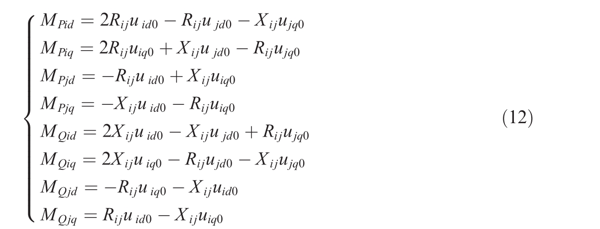
For any node in the AC system,the micro-increment of the power injected into the node can be described as

where n is the number of the node connected to node i,ΔPi is the incremental power injected into the node,and ΔPij is the micro incremental power of the branch.
Combined with the power micro-increment expression and system structure of the nodes and branches, the micro-increment model of the entire system on the AC side can be obtained as follows:
where ΔP and ΔQ are the micro increments of the power injected by the nodes, which are different from the definitions of ΔPij and ΔQij in(11);Δud and Δuq are the column vectors of node voltage micro-increments, and MΔ is the corresponding coefficient matrix derived from the matrix M in (11).
2.2 Constraint of control type
Different constraints must be added depending on the VSC type.For converters with constant power control, it can be approximated that the micro-increment of power is always zero; therefore, the following constraints can be added to the aforementioned micro-incremental model:

when the VSC is applied to the interconnection in the segmentation,the rectifier and inverter sides are connected to the receiver system.The main purpose of using VSC segmentation is to maintain the power balance of the system,improve the voltage stability of the receiving system, and provide reactive power support in case of failure.Therefore, the control mode that must be adopted sets the DC power and AC voltage amplitude on one side and the DC and AC voltage amplitudes on the other side.With constant-voltage amplitude control, the VSC can dynamically support reactive power.
If the phase-locked loop (PLL) of the VSC takes the phase angle of the grid-side node as the reference value,the value of uvq becomes zero, and (6) can be rewritten as follows:

Constant voltage amplitude control in Laplace domain can be described as:
where Kp is the proportional gain, Ki is the integral coeffi-cient,Vref is the reference voltage,Vm is the grid-side voltage, and iqref is the reference q-axis current.
Voltage sag occurs when a slight fault occurs in the system.This changes the amplitude and angle.However, the reference of the PLL cannot be changed immediately,which means that uvq is no longer zero, and the reactive power in (16) becomes
Here, u′v_d, u′v_q, i′v_d, and i′v_q are the voltages and currents after failure and Q′VSC is the reactive power of VSC after failure.
In slight voltage sag, the angle does not change significantly, therefore the u′v_d is slightly smaller than uv_d and larger than u′v_q.Moreover, because of the PI controller in (17), the q-axis current increases significantly, so i′v_q in(18)is larger than iv_q.For the above two reasons,Q′VSC is larger than QVSC; therefore, the reactive power support from VSC increases after failure.
In general,if the fault does not exceed the VSC support capability,the voltage amplitude can be maintained at the reference value after failure, and the current and reactive power injected from the VSC will increase.After the fault is cleared, the above index is restored to the initial condition.
Considering this control mode,the following constraint can be added to the micro-incremental model:

In combination with (5), (7), and (14), the operating impedance of the converter can be calculated by considering (15) and (19) for converters with different control types.
3 Influence of VSC
After obtaining the operating impedance of the converter, the system shown in Fig.1 in the steady state can be made equivalent, as shown in Fig.3.
In the figure,ZVSC1 and ZVSC2 are the equivalent impedances on both sides of the converter.In an incompletely segmented system, the VSC replaces the original AC line to reduce the LCC connection strength.In the steady state,the operating impedance can be used to quantitatively analyze the change in connection strength by calculating the MIIF.
The AC side of a multi-DC system can be described as follows:
where U is the node voltage, Z is the node impedance matrix, I is the node injection current, and elements Zmn in rows m and n of the node impedance matrix represent the mutual impedance between nodes m and n.
After segmentation, the system topology is changed to that shown in Fig.2.One AC branch is disconnected,and a new grounding impedance branch is added to the nodes on both sides of the branch.Accordingly, the node impedance matrix and corresponding elements also change.
3.1 Influence of VSC on MISCR
In the definition of MIIF, the calculation holds when the system voltage changes by a small degree; therefore,the micro-incremental model can be used as equivalent to VSC.After considering the operating impedance of the VSC, the MIIF changes, and (3) becomes
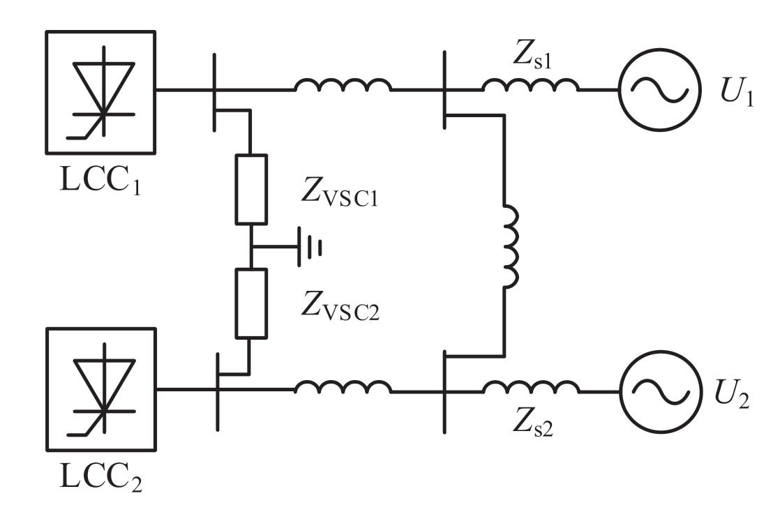
Fig.3.Topology of the equivalent system.
The influence of the converter on the degree of DC electrical coupling can be obtained by comparing the changes in the MIIF.
In addition to the MIIF, the influence of the VSC on the short-circuit capacity must also be discussed.In a traditional AC system, the short-circuit capacity can directly measure the ability of the traditional power supply to support the system voltage, as shown in (22).
Here, Sac is the short circuit capacity, UN is the rated voltage of the short circuit point, and If is the threephase short circuit current.
However,because the converter control loop contains a current-limiting link, the short-circuit current of the converter and traditional power supply exhibit different response characteristics in short circuits.Therefore, when the system contains a converter, (22) cannot be used directly for the calculation,and the traditional power supply and converter must be considered separately [25].
The output current of the converter was analyzed using the coordinate system of the d-and q-axes,and the output current of the VSC to the AC power grid is:
The controller enables the VSC to maintain the stability of the output power or AC voltage amplitude.When the AC power grid fails, the converter adjusts the current injected into the power grid based on the parameters and logic of the control link.Based on the degree of influence of the fault on the VSC feed point, the current loop exhibits different responses.
When a fault on the AC side has no significant impact on the converter,the converter can maintain the basic AC voltage of the port, and the power is exchanged on both sides of the partition.At this point, (16) becomes

where Pref and uref are the command values of the active power and voltage, respectively; Pf and Qf are the active power and reactive power outputs of the VSC after the fault,respectively;and idf and iqf are the d-and q-axis current outputs of the converter after the fault, respectively.
When a fault on the AC side has a significant impact on the converter, the converter cannot stabilize the portvoltage amplitude.At this time, the input reactive power of the converter to the system reaches the upper limit,and the corresponding Q-axis current iq also reaches the upper limit.As the port voltage drops, the D-axis current also increases to the upper limit to maintain the active power stability.
If traditional short-circuit capacity analysis is used, the converter fault cutting machine will not inject short-circuit current into the system when a severe system fault occurs;that is, it will not change the short-circuit capacity of the system.This is unreasonable because,before the fault cutter, the converter injects a large amount of reactive power into the system, and its voltage support ability is reflected in the fault process.Therefore, it is necessary to consider the influence of the converter on the short-circuit capacity of the system from other perspectives.
Owing to the control link, the converter can adjust the active and reactive powers injected into the system according to the control instructions;therefore,when considering the effect of the converter on the short-circuit capacity,the maximum capacity of the converter should be considered directly.
The equivalent operating impedance of the converter at this time is:
At this time, the equivalent operating impedance of the converter is infinite;the converter is equivalent to a current source and should provide support to the system according to the maximum capacity of the steady state.After segmentation, the fault in the partition near the LCC is blocked by the VSC,and the voltage drop in the other partition is lower.Therefore,when analyzing the short-circuit capacity, only the LCC near-area VSC can be considered.
Therefore, after the system is segmented, the shortcircuit capacity comprises two parts: the short-circuit capacity provided by the AC system and the short-circuit capacity provided by the VSC, given as follows:

Here, Sac1 is the short-circuit capacity contributed by the traditional power supply, Sac2 is the short-circuit capacity contributed by the VSC,and Uref is the converter line voltage command value.The short-circuit ratio index of the system after segmentation can be calculated by combining (3), (4), and (26).
3.2 Intensity comparison under different segmenting modes
Incomplete and complete segmentations affect the strength of the system.According to the above analysis,the VSC reduces the coupling effect between the LCCs.In a completely segmented system,there is no AC connection between the LCCs;therefore,the MIIF becomes zero.When the short-circuit ratio index is used, the DC in incomplete segmentation must be analyzed by MISCR.In complete segmentation, the multi-infeed system is divided into two single-feed systems because the MIIF becomes zero.Therefore, the traditional single-feed SCR can be used to analyze the DC strength.
Fig.1, without line Z3, shows the topology of a completely segmented system.After complete segmentation,there is no coupling between the two LCCs and the short-circuit capacity changes.Therefore, the calculation of the single-feed short-circuit ratio after complete segmentation becomes
where S′′ac is considering the short-circuit capacity of the converter and system topology changes and Pdc is the power fed by the LCC.
By comparing the SCR of (27) and MISCR of (4)before segmentation,the influence of complete and incomplete segmentation on the LCC strength can be analyzed.
4 Example analysis
Based on the above theory, a doubly-fed LCC model was built on the EMTDC/PSCAD simulation platform.The system structure is shown in Fig.1.The model was a basic and incompletely segmented system.The simulation presented in this section is a case of an incompletely segmented system.The simulation focused on the comparison between incomplete segmentation and unsegmentation.
Among these,the CIGRE benchmark was used for two LCC-HVDCs, and some modifications were made based on this.The transmission power of both LCCs was 1000 MW, and the control modes were rectifier-side fixed current control and inverter-side fixed turn-offangle control.The AC side had U1 = 230∠-2.5 , U2 = 230∠0
 ; for simplicity in calculation, we ignore the resistance of the AC branch.
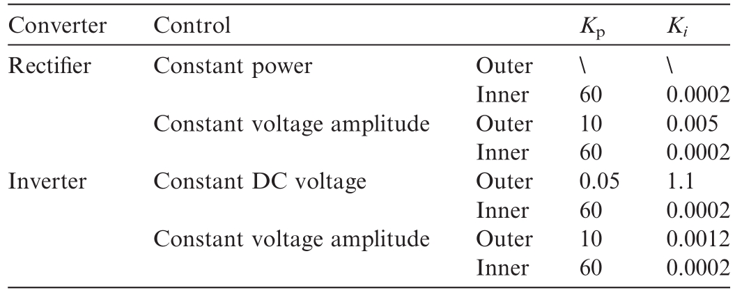
In this model, the VSC rectifier side adopts constant power and AC voltage amplitude control, whereas the inverter side adopts constant DC and AC voltage amplitude control.The specific parameters of the control link are listed in Table 1.
4.1 Calculation of MIIF based on the operating impedance
During system operation, a shunt reactor was connected at the LCC1 feed point for 1.5 s to reduce the voltage of the LCC1 converter bus.The voltage of the LCC2 converter bus was observed, and the MIIFs before and after VSC segmentation were compared by simulation with the MIIF obtained by theoretical calculation.
According to the calculation of the MIIF using(3),(4),and (21), combined with the simulation in Fig.4, the results shown in Table 2 can be obtained by comparing the MIIFs before and after VSC segmentation:
The MIIF results after segmentation show that it is feasible to operate the impedance equivalent converter, andthe MIIF between the two LCCs is significantly reduced after segmentation based on the VSC;that is,the AC connection strength is reduced.
Table 1
Parameters of control system.
4.2 Short-circuit fault simulation analysis
In a segmented system, the voltage support ability of the converter to the power grid under fault conditions is an important factor for measuring the effect of the converter on the power grid strength improvement.
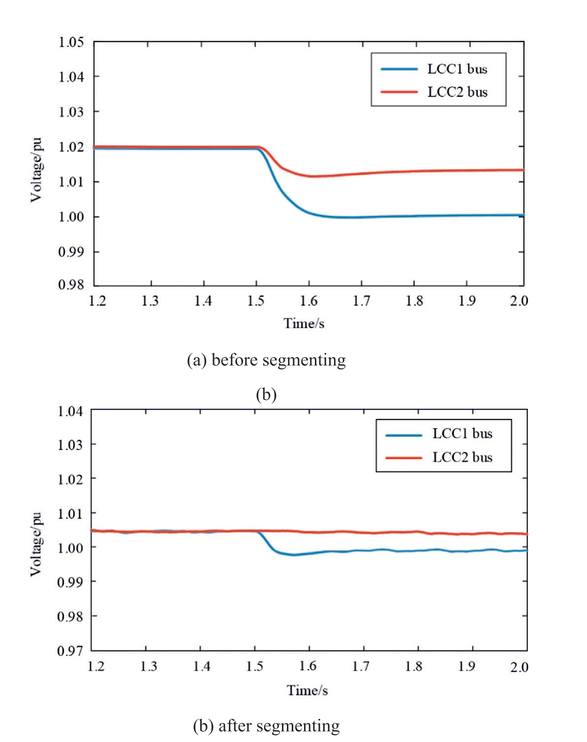
Fig.4.Simulation result of MIIF.
Table 2
Comparison of MIIF.

Because the analysis methods for both sides of the converter are similar,only one side of the converter is considered as the main analysis object, and the fault is applied differently such that the voltage drop of the converter is different.
In all examples,the fault is set at 1.5 s and lasts for 0.5 s.First, the drop in the LCC1 converter bus voltage before and after segmentation is compared when LCC2 is faulty in the near area and different ground resistances are set.
As shown in Fig.5, the VSC is used to segment the multi-infeed system, effectively blocking fault propagation between partitions.Under the action of the converter, the fault near one LCC cannot easily affect the other LCC.
The currents of the d-and q-axes of the fault-measuring converter under different fault degrees are shown in Fig.6,and the current limits of the d- and q-axes is 3 kA.
When an AC system has a mild fault,the converter provides reactive power to the system to maintain a constant voltage.At this time,the q axis current increases and the d axis current remains unchanged, corresponding to the ground resistance of 20 Ω in Fig.6.
When the AC system fault is relatively serious, the current of the converter appears in two situations: when the fault ground resistance is 5 Ω, the current in the q axis reaches the upper limit, and the current of the d axis does not; the active power command can be maintained.When the fault ground resistance is 0.5 Ω, the currents in the d and q axes reach the upper limit, and the active power command cannot be maintained at this time.
The short-circuit currents near the two LCC feed points before and after segmentation are shown in Fig.7.
The voltage drop in the LCC1 converter bus when a fault occurs near LCC1 is shown in Fig.8.
The comparison results for the short circuit capacity at the LCC1 feed point are listed in Table 3.
In Table 3, Algorithm 1 is calculated directly using the short-circuit current and rated voltage,whereas Algorithm 2 is calculated using the maximum capacity of the current source with infinite impedance.
Combining Fig.7, Fig.8, and Table 3, it can be seen that although the system short-circuit current is reduced after segmentation, the resistance of the LCC feed point to the voltage reduction is slightly improved.Therefore,the method for calculating the short circuit capacity using the short circuit current is not applicable to the scenario after VSC segmentation.
The LCC intensity under different segmentation methods is shown in Table 4.
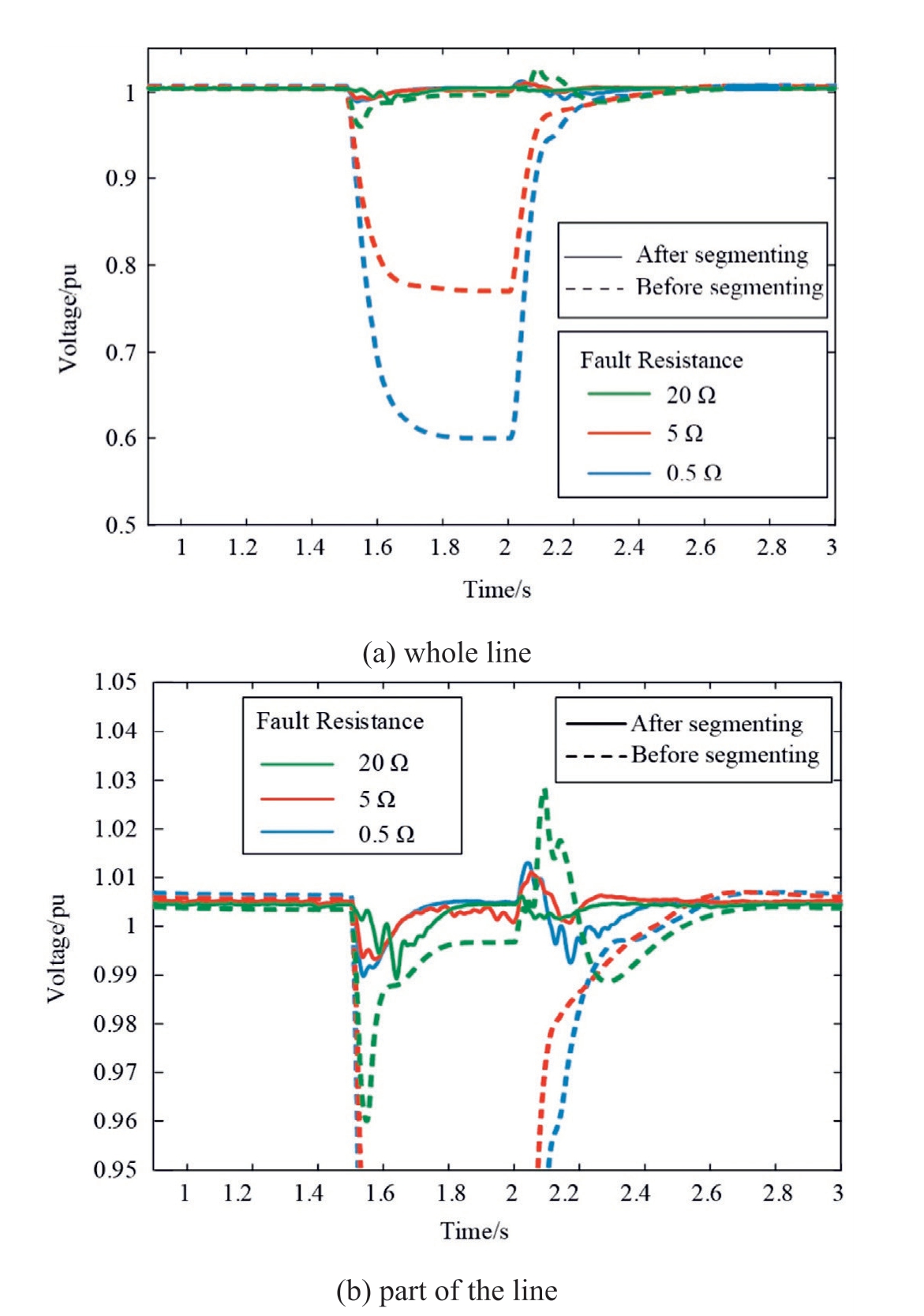
Fig.5.Comparison of converter bus voltages in the segmented system.
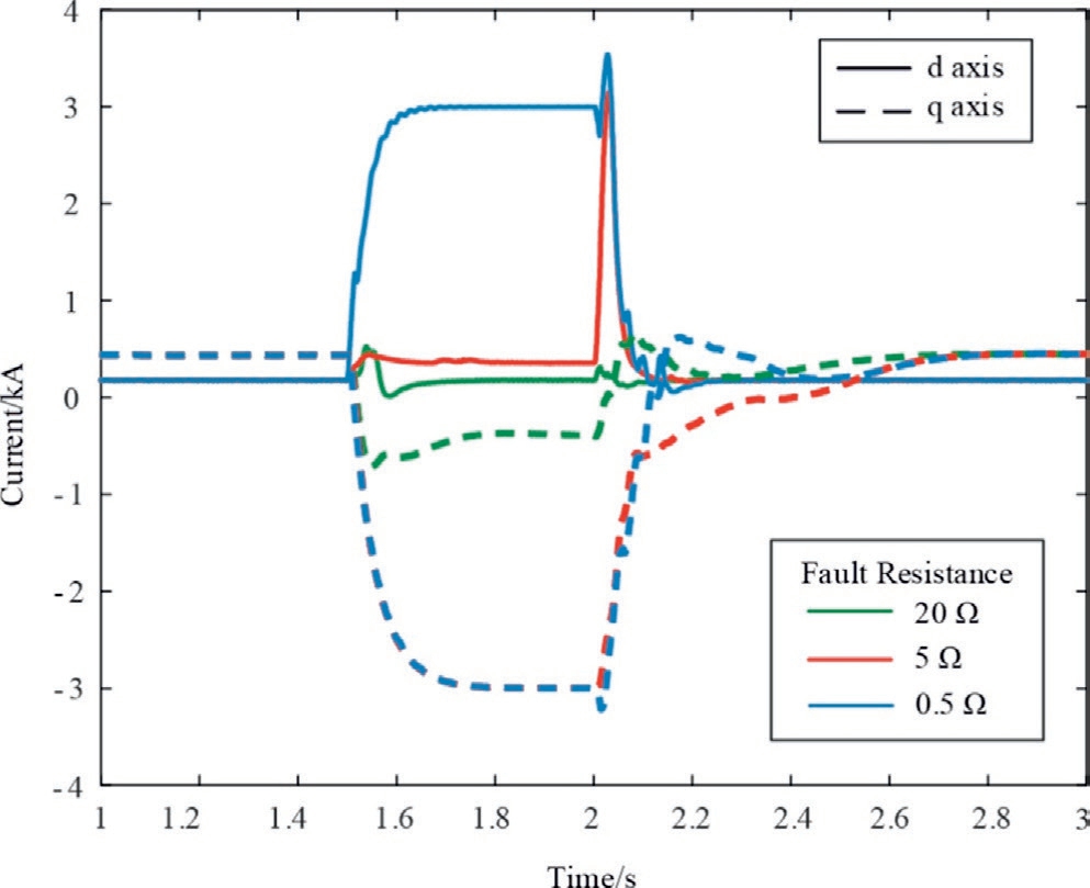
Fig.6.The d-q axis current of the converter in different fault degrees.
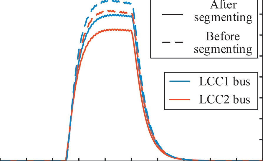
Fig.7.The short-circuit current of the LCC converter bus in the segmented system.
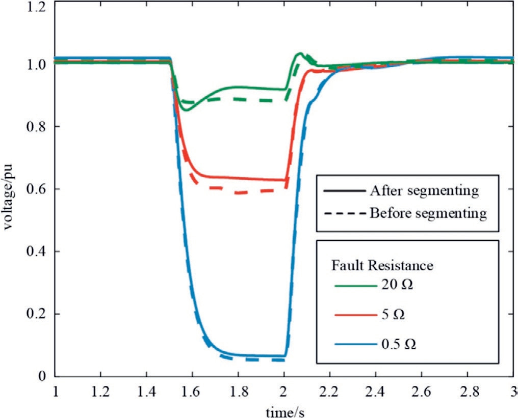
Fig.8.Comparison of the converter bus voltage falling in the segmented system during short-line fault.
Table 3
Result of short-circuit capacity (MVA).

Table 4
Result of MISCR.

When the system is incompletely segmented, the shortcircuit capacity of the system does not change significantly,and the short-circuit ratio increases owing to a reduction in the MIIF.From Table 4 and Figs.5 and 8, it can be observed that incomplete segmentation can improve the strength of the system.
5 Conclusion
Aiming at the problem of multi-infeed DC system segmentation, this study investigated the incomplete segmentation of a receiver system using a VSC.To analyze the effect of the VSC on the receiver system in incomplete segmentation, micro-incremental models of the VSC and AC systems were established.The MIIF was calculated using the micro-increment model to equate the converter to the impedance under steady-state and fault conditions.Finally, the MISCR suitable for segmentation based on the VSC scenario was calculated.
Through theoretical calculations and simulation analysis, the main conclusions are as follows: (1) Using the power characteristics of the VSC and power grid, a micro-incremental model can be established.The VSC can be considered equivalent to an impedance based on the micro-incremental model,which can be used to analyze the VSC.(2) The VSC can be used to segment a multiinfeed DC system, which can support the receiving system voltage, provide reactive power under the fault, and prevent the fault from spreading between the partitions.Thus,incomplete segmentation can enhance multi-infeed systems.(3) The traditional short-circuit capacity calculation method is not suitable for an incompletely segmented system based on the VSC.The VSC should be equivalent to the current source with infinite impedance, which is directly equivalent according to its maximum capacity.
CRediT authorship contribution statement
You Zuo:Writing-original draft,Validation,Software,Formal analysis, Data curation. Minxiao Han: Writing -review & editing, Methodology, Conceptualization. Bing Liu: Supervision, Investigation, Funding acquisition.Tamara Egamnazarova: Writing - review & editing.
Declaration of competing interest
The authors declare that they have no known competing financial interests or personal relationships that could have appeared to influence the work reported in this paper.
The authors declare the following financial interests/personal relationships which may be considered as potential competing interests:Bing Liu is currently employed by Central China Branch, State Grid Corporation of China.
Acknowledgments
This work was supported by the State Grid Science and Technology Project 5108-202218280A-2-87-XG.
References
[1]N.M.Haegel, S.R.Kurtz, Global progress toward renewable electricity:tracking the role of solar(version 2),IEEE J.Photovolt.12 (6) (2022) 1265-1272.
[2]R.Adapa, High-wire act: HVdc technology: the state of the art,IEEE Power Energ.Mag.10 (6) (2012) 18-29.
[3]X.Baoan, G.Mingqun, W.Shaowu, et al., Friendly HVDC transmission technologies for large-scale renewable energy and their engineering practice, Autom.Electr.Power Syst.45 (22)(2021) 1-8.
[4]X.Yunfei, J.Guofeng, L.Yang, et al., Outward transmission capacity analysis under the background of UHV AC/DC power grid, High Volt.Appar.54 (10) (2018) 33-37.
[5]W.Bin,X.Youping,D.Jie,et al.,Evolutional features and defense system construction of central China power grid dynamic stability,Power Syst.Technol.45 (8) (2021) 3238-3246.
[6]D.L.H.Aik, G.Andersson, Analysis of voltage and power interactions in multi-infeed HVDC systems, IEEE Trans.Power Del.28 (2) (2013) 816-824.
[7]E.Rahimi, A.M.Gole, J.B.Davies, et al., Commutation failure analysis in multi-infeed HVDC systems, IEEE Trans.Power Del.26 (1) (2011) 378-384.
[8]M.Jiang, Q.L.Guo, H.B.Sun, et al., Short-term voltage stabilityconstrained unit commitment for receiving-end grid with multiinfeed HVDCs,IEEE Trans.Power Syst.36 (3) (2021) 2603-2613.
[9]Y.C.Zhang,Y.Xu,Z.Y.Dong,et al.,A hierarchical self-adaptive name="ref10" style="font-size: 1em; text-align: justify; text-indent: 2em; line-height: 1.8em; margin: 0.5em 0em;">[10]D.Yang, K.Zhao, Y.T.Liu, Coordinated optimization for controlling short circuit current and multi-infeed DC interaction,J.Mod Power Syst.Clean Energy 2 (4) (2014) 274-284.
[11]C.Wantong, H.Chao, Z.Baorong, et al., Research on structure change from double-ring to cluster of Guangdong power grid,Proc.CSEE 40 (20) (2020) 6557-6568.
[12]X.J.Ni,A.M.Gole,C.Y.Zhao,et al.,An improved measure of AC system strength for performance analysis of multi-infeed HVDC systems including VSC and LCC converters, IEEE Trans.Power Del.33 (1) (2018) 169-178.
[13]Y.K.Kim, G.S.Lee, C.K.Kim, et al., An improved AC system strength measure for evaluation of power stability and temporary overvoltage in hybrid multi-infeed HVDC systems, IEEE Trans.Power Del.37 (1) (2022) 638-649.
[14]T.Baoye,Y.Zhichang,Y.Xinyue,et al.,Influence of VSC-HVDC on the strength of LCC-HVDC receiving power grid in hybrid dual-infeed HVDC system, Proc.CSEE 39 (12) (2019) 3443-3454.
[15]L.Wei, G.Chunyi, Y.Shuo, et al., Research on Interaction mechanism of hybrid dual-infeed HVDC system (part I):equivalent single-infeed HVDC model, Proc.CSEE 40 (18) (2020)5911-5921.
[16]L.Wei,G.Chunyi,Y.Shuo,et al.,(2020)Research on interaction mechanism of hybrid dual-infeed HVDC system (part Ⅱ): smallsignal stability margin analysis, Proc.CSEE 40 (19) (2020) 6113-6121.
[17]R.F.Mochamad, R.Preece, Assessing the impact of VSC-HVDC on the interdependence of power system dynamic performance in uncertain mixed AC/DC systems, IEEE Trans.Power Syst.35 (1)(2020) 63-74.
[18]W.Y.Cao, M.X.Han, X.H.Zhang, et al., A novel power sharing scheme of controlling parallel-operated inverters in islanded microgrids, IEEE J.Emerg.Select.Topics Power Electron.9 (5)(2021) 5732-5746.
[19]M.F.M.Arani, Y.A.R.I.Mohamed, Analysis and performance enhancement of vector-controlled VSC in HVDC links connected to very weak grids,IEEE Trans.Power Syst.32(1)(2017)684-693.
[20]C.Xin, H.Minxiao, S.Hongbo, et al., Determination method for accessing location of VSC-HVDC in segmented multi-infeed LCCHVDC system, Autom.Electr.Power Syst.45 (13) (2021) 20-29.
[21]J.B.Zhu, Z.P.Shen, L.J.Yu, et al., Bilateral inertia and damping emulation control scheme of VSC-HVDC transmission systems for asynchronous grid interconnections, IEEE Trans.Power Syst.38(5) (2023) 4281-4292.
[22]A.Rodriguez-Cabero, J.Roldan-Perez, M.Prodanovic, et al.,Coupling of AC grids via VSC-HVDC interconnections for oscillation damping based on differential and common power control, IEEE Trans.Power Electron.35 (6) (2020) 6548-6558.
[23]C.Xin, H.Minxiao, M.Limin, Segmentation method of a multiinfeed method LCC system based on local fitness measure, Adv.Technol.Electr.Eng.Energy 40 (6) (2022) 32-42.
[24]X.Y.Chen, A.M.Gole, M.X.Han, Analysis of mixed inverter/rectifier multi-infeed HVDC systems, IEEE Trans.Power Del.27(3) (2012) 1565-1573.
[25]X.Zheng, Reasonable definition and calculation method of power grid strength under the background of new type power systems,High Volt.Eng.48 (10) (2022) 3805-3819.
Received 10 June 2024;revised 7 September 2024; accepted 10 October 2024
Peer review under the responsibility of Global Energy Interconnection Group Co.Ltd.
* Corresponding author.
E-mail addresses: zetazy91@126.com (Y.Zuo), corresponding_han@163.com (M.Han), liubing@cc.sgcc.com.cn (B.Liu), Tegamnazar@gmail.com (T.Egamnazarova).
https://doi.org/10.1016/j.gloei.2024.10.015
2096-5117/© 2025 Global Energy Interconnection Group Co.Ltd.Publishing services by Elsevier B.V.on behalf of KeAi Communications Co.Ltd.This is an open access article under the CC BY-NC-ND license(http://creativecommons.org/licenses/by-nc-nd/4.0/).

You Zuo received the B.S.degree in electrical engineering from North China Electric Power University, Beijing, China.Currently, he is studying for M.S.degree at North China Electric University.His main research interest includes HVDC and power electronics.

Minxiao Han received the Ph.D.degree in electrical engineering and automation from North China Electric Power University(NCEPU), Beijing, China, in 1995.He is currently the Director of Institute of Flexible Electric Power Technology, NCEPU.His research interests the applications of power electronics in power system including HVDC,FACTS, and power conversion and control.

Bing Liu received Ph.D.degree in electrical engineering from Wuhan University.He is working in State Grid Corporation of China,Central China Branch.His research interests include power system and power electronics.

Tamara Egamnazarova received B.S.and M.S.degrees in electrical engineering from Tashkent State Technical University.She is currently pursuing a Ph.D.degree in electrical and electronic engineering at North China Power University.Her research focuses on harmonic propagation and stability analysis.
(Editor Zedong Zhang)
