0 Introduction
Numerous electronic power devices,new energy vehicles,and distributed generation (DG) systems are integrated into distribution networks.The volatility and randomness of these elements result in power imbalances in feeders and voltage-overlimit conditions [1-3].Therefore,flexible interconnection devices based on power-electronics technology have been proposed to replace tie switches,which is a significant trend in the fields of electronic and intelligent power systems [4,5].
A flexible multistate switch (FMS) is employed to connect multiple feeders,thus enabling the continuous control of both active and reactive power for each port and realizing a dynamic capacity increase and flexible interconnection of local distribution networks [6,7].Unlike tie switches,the FMS eliminates the issue of shocks caused by opening/closing switches and is not limited by the number of switching times.Furthermore,the FMS can enhance the absorption capacity of DG and energy storage systems (ESS) from its direct current (DC) side without a DC power supply.In various application scenarios,FMSs have been utilized to address problems such as three-phase voltage imbalance,power fluctuations,and current ripples[8-10] to enhance the overall system efficiency.Methods such as sliding mode control (SMC) and model predictive control [11,12] are applied in FMSs to improve the system’s control performance and robustness in complex environments through flexible state switching.
In addition,researchers have integrated flexible arc suppression into FMSs to eliminate single-phase ground(SPG) fault currents [13].However,existing active arcsuppression devices have a single function and operate only when an SPG fault occurs,thus resulting in the low utilization of power electronic switches and necessitating independent DC power supplies,which results in high equipment costs and bulkiness.Therefore,multifunctional and intelligent active power electronic equipment is an important future development trend [14].Tu et al.proposed a flexible arc-suppression method based on a unified powerquality conditioner [15].In this method,the power quality is regulated when distribution networks operate normally and the SPG fault current is fully compensated by the injection current.Zhang et al. [16] employed multivariable decoupling control to enable a three-phase cascade H-bridge converter to integrate active and reactive power compensation as well as realize flexible arc suppression.However,this method requires an additional DC power supply.Most of the aforementioned studies rely on classical control theories,which exhibit low dynamic responsiveness and limited robustness.
Unlike classical control theories,SMC offers a customized nonlinear approach to address the shortcomings above,which includes the design of a sliding-mode surface and the reaching law.Various sliding-mode surfaces,including terminal and higher-order sliding-mode surfaces,improve the convergence speed via a higherorder exponential term.This ensures that the system state reaches the sliding-mode surface in finite time and exhibits remarkable convergence performance.The nonlinear components within the reaching law,namely,the sign and saturation functions,eliminate the effect of disturbances through high-frequency switching and provide greater robustness.This control characteristic can effectively mitigate the disturbances caused by the randomness of DG and parameter perturbations in real-world distribution networks,thereby improving system stability.Nevertheless,factors such as time lag switches,spatial lag switches,and system inertia can induce signal oscillations and trigger unmodeled system dynamics,thus ultimately compromising the control precision [17-19].To alleviate signal oscillations,scholars have proposed various methodologies,including boundary-layer approaches,reaching-law techniques,and intelligent sliding-mode strategies.Boundary-layer approaches utilize a saturation function to achieve a smooth transition near the sliding-mode surface,thus weakening chattering [20].Reaching-law techniques dynamically adjust the speed for reaching the sliding-mode surface,thus reducing the buffeting effect [21].Intelligent sliding-mode strategies include the neural-network sliding mode [22] and adaptive sliding mode.By leveraging the attributes of self-learning,inheritance,adaptiveness,and evolution inherent in intelligent control,the output of SMC can be adapted based on the system state,thus effectively mitigating buffeting.For parallel inverters,Yang et al.[23] proposed an SMC method based on an adaptive fully robust fuzzy neural network (FNN),which improves the output-power quality and current-sharing performance of dual inverters.For the dynamic approximation of unknown dynamic system equations of a microgyroscope,Fei et al. [24] designed a multilayer recursive FNN based on an adaptive fractional-order sliding-mode controller.Compared with the conventional FNN,a multilayer recursive FNN exhibits better dynamic mapping capability [25].Although the FNN can approximate any nonlinear control law of SMC,the upper bound of the lumped uncertainty must be considered in the design of parameters to ensure the accessibility of the sliding surface [26].However,the upper limit remains unclear.The oversized parameters may amplify oscillations,whereas smaller parameters can compromise the robustness.
To address these issues,this study focuses on a multifunctional FMS with power interactions and flexible arc suppression.An SMC method based on an improved double-loop recursive fuzzy neural network (DRFNN) is presented.The key innovations of this study are as follows:
1) The classical FNN architecture is improved by introducing a dual-weight recursive DRFNN design,which improves its global learning proficiency.This innovative structure effectively mitigates the issues of chattering and transient overshoot.
2) A calculus-driven sliding-mode surface is created,which obviates the necessity to compute the second derivative of the prevailing error.The theoretically derived control law for the 0-axis voltage is instrumental in elevating both the fault-current rejection rate and responsiveness.
3) A quasi-continuous second-order sliding mode controller (QS-SMC) is designed to alleviate chattering caused by the oversized sliding-mode parameters.This controller augments the approximation accuracy of the FNN and reinforces the overall stability of the control system.
1 Operating principle of FMS
1.1 Interconnected distribution networks with FMS
A three-port flexible interconnected distribution network comprises independent back-to-back voltage-source converter (VSC).The FMS is installed at the terminations of different feeders within 10 kV distribution networks to implement flexible power control at each port,as shown in Fig.1.A modular multilevel converter (MMC) topology is adopted for each port,where the upper and lower bridge arms are constructed using cascaded half-bridge submodules,as shown in Fig.2.Herein,iza,izb,and izc are the AC currents of the VSC;ipa,ipb,and ipc are the three-phase currents of the upper bridge arms;iwa,iwb,and iwc are the three-phase currents of the lower bridge arms;usa,usb,and usc are the supply voltages;LH and RH are the inductances and resistances of the bridge arms,respectively;Lstat and Cstat are the inductance and capacitance of the LC filter circuit,respectively;and udc is the DC-link voltage.In the case of grounding faults within the distribution networks,the DC-link ground point O provides a pathway for the zerosequence current.
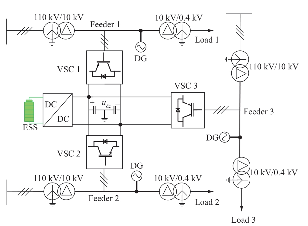
Fig.1 Flexible interconnected distribution network
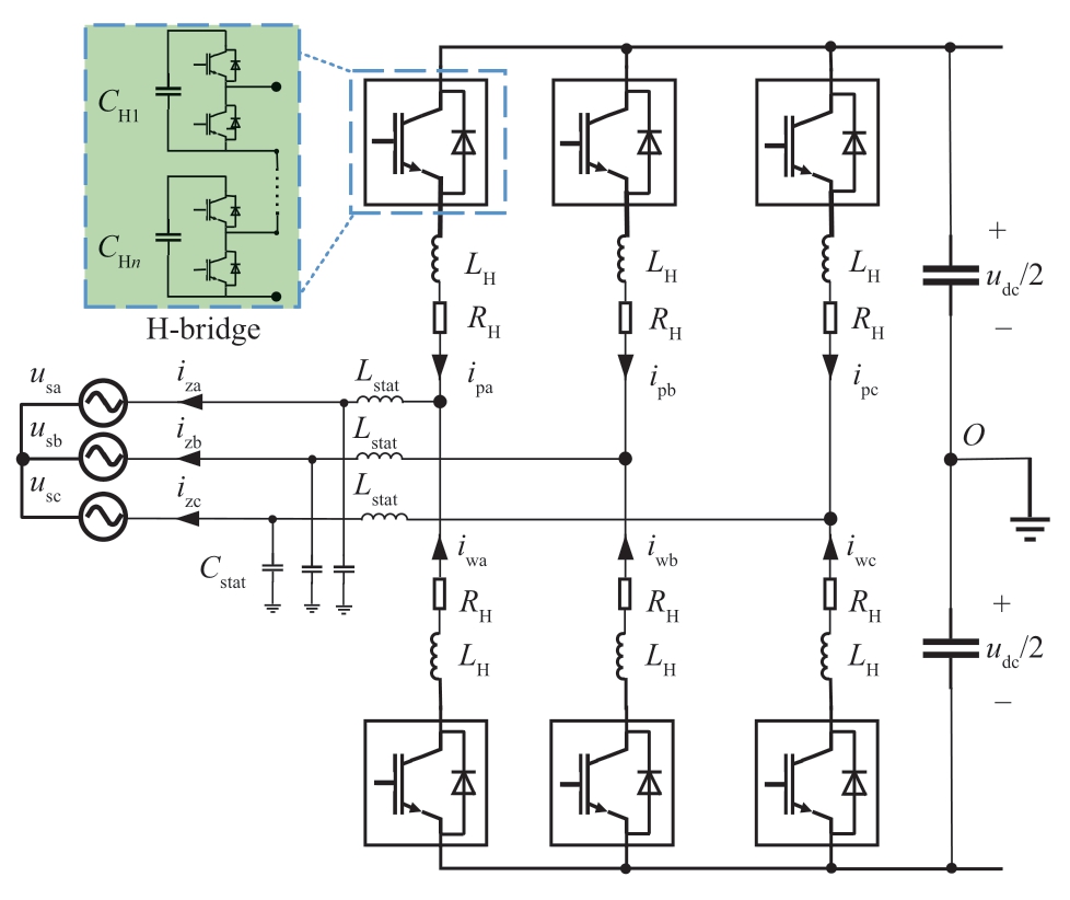
Fig.2 Topology structure of MMC
1.2 Mathematical model of power interaction
Because the three-terminal FMS is symmetrically structured,one of the ports is selected for a detailed analysis.Based on Kirchhoff ’s voltage law,the mathematical model of the FMS in a stationary coordinate system is established as follows:

where k is equal to a,b,or c,which represent the A,B,or C phases,respectively;and uk1 and uk2 are the total threephase output voltages of the upper and lower bridge arms,respectively,with the condition that uk1 is equal to -uk2.
According to Kirchhoff ’s current law,the output current at the AC side izk can be expressed as
Adding (1) and (2),followed by dividing the result by 2 and finally combining it with (3) yields
By converting the equation above from the abc coordinate system to the dq coordinate system,(4) can be rewritten as

where ω is the angular frequency of the phase voltage;(izd,izq) and (usd,usq) are the output currents and supply voltages at the AC side on the d-and q-axes,respectively;and ud and uq are the components of the three voltages on the d-and q-axes,respectively.
1.3 Arc-suppression principle of flexible current
The FMS serves as an active arc-suppression device that facilitates rapid SPG fault recovery.The energy required for arc suppression is obtained from the nonfault feeders or the DG on the DC side.Consequently,additional DC power supplies are not required,which reduces the volume and cost of the device substantially and improves the costeffectiveness of distribution networks.As shown in Fig.3,an SPG fault is assumed to occur in the A phase of feeder 1 with a grounding resistance denoted as Rf1.The line impedance is not considered,and the three-phase relative ground parameters are approximately symmetric,i.e.,the leakage resistances r0an=r0bn=r0cn=r0n (n=1,2,or 3 indicates the feeder number) and ground capacitances C0an=C0bn=C0cn=C0n.By applying Kirchhoff ’s current law,the relationship between the fault current If1 and zero-sequence current I01 is written as follows:
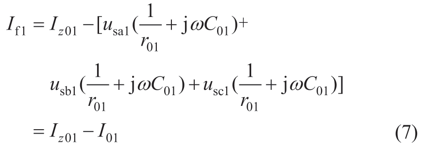
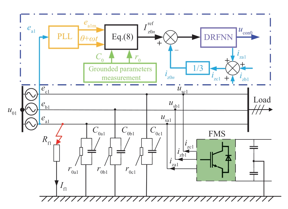
Fig.3 Single-phase grounding fault in flexible interconnected distribution network
where ek1,usk1,and u01 are the instantaneous values of the supply voltage,the voltage at the point of common coupling,and the neutral voltage in feeder 1,respectively.Specifically,usk1=ek1+u01 and ea1+eb1+ec1=0.Iz01 denotes the zero-sequence injection current.
When the FMS fully compensates for the SPG fault current,i.e.,Iz01=I01,the fault current If1 is suppressed to zero.According to Ohm’s theorem,the fault-phase voltage usa1=0.Substituting these values into (7),the reference current ![]() of port 1 can be represented as
of port 1 can be represented as

In scenarios where SPG faults occur at both ends of flexible interconnected distribution networks,the control of the injection current at each end does not interact with each other [13].Let the output currents be ![]() and
and ![]() to achieve flexible arc suppression at both ends,thus effectively reducing the ground-point current to approximately zero.The zero-sequence current transmission paths are shown in Fig.4,in which the dashed green and purple lines represent the zero-sequence current transmission routes of feeders 1 and 2,respectively.Clearly,the zerosequence currents interact with each other on the DC side.To prevent the transfer of the zero-sequence current to the nonfault end,one must suppress the zero-sequence current at the nonfault end to zero,i.e.,
to achieve flexible arc suppression at both ends,thus effectively reducing the ground-point current to approximately zero.The zero-sequence current transmission paths are shown in Fig.4,in which the dashed green and purple lines represent the zero-sequence current transmission routes of feeders 1 and 2,respectively.Clearly,the zerosequence currents interact with each other on the DC side.To prevent the transfer of the zero-sequence current to the nonfault end,one must suppress the zero-sequence current at the nonfault end to zero,i.e.,![]()
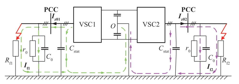
Fig.4 Zero-sequence current transmission paths when two-terminal grounding fault occurs
2 Control strategy
The operation modes of the FMS include the udc-Q mode,P-Q,and V/f modes [12].Where P and Q are the active and reactive power outputs of the FMS,respectively;V and f are DC voltage and frequency,respectively.These modes exhibit similar control structures and differ primarily in their input signals.Next,consider the udc-Q mode as an example.To improve the flexible regulation,output power quality,and control stability of the FMS,a DRFNN slidingmode controller is employed in the inner current loop,whereas PI control is adopted in the outer voltage loop to maintain a constant DC-link voltage and obtain the reference values of the d-and q-axis currents,as shown in Fig.5.Here,sdc and sQ are obtained from the DC-link voltage error edc and reactive power error eQ,respectively,through the integral SMC.These values,along with sdq,serve as inputs for the d-and q-axes of the DRFNN,thus enhancing the global learning ability of the neural network and further improving the control accuracy.By incorporating adaptive learning for internal parameters,the control law of SMC is approximated online to mitigate chattering and reduce the reliance on parameter acquisition.The QS-SMC is used to enhance the compensation accuracy of the FNN and ensure the control stability.
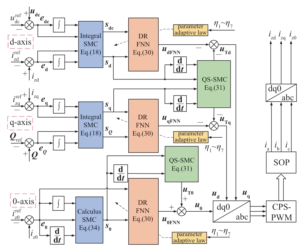
Fig.5 Block diagram of current-loop control system under udc-Q mode
2.1 System description under lumped uncertainty
Based on the mathematical model of the FMS,the primary control objective of the FMS is to enable signals on the dq-and 0-axes to accurately monitor the current reference values.Based on (5) and (6),the system state equation can be expressed as

where x=xdq0=[izd izq iz0]T is the state variable;u=[ud uq u0]T indicates the system output;f(x)=[-RH xdq0/2+W xdq0 +usdq0]/L;y is the input of the FNN;H=diag (3,3)/L,where L=Lstat+LH/2;diag(3,3) represents the 3 × 3 identity matrix;W=[0 ω 0 ;-ω 0 0];and usdq0=[usd usq us0]T.
Equation (9) represents an idealized mathematical model.However,in practical applications,where the parameter variations,measurement accuracy,and external interference must be considered,the actual dynamic mathematical model of the system can be expressed as
where Δf(x)=f(x,ΔRH,ΔL),ΔH=H(ΔL) denote the difference between the actual and nominal values,and g(t)is the external disturbance.
The lumped uncertainty D is expressed as
It represents the cumulative of all uncertainties,with the assumption of an upper limit,i.e.,‖ D ‖ ≤ Dmax;therefore,(10) can be expressed as
where F(x)=f (x)/H.
2.2 Integrated sliding-mode controller design
The monitoring error can be defined as


The classical linear sliding-mode surface can be expressed as
where s=[sd sq s0 sdc sP sQ]T,e=[ed eq e0 edc eP eQ]T,and kn=[knd knq kn0 kndc knP knQ]T.
A relative order restriction problem exists in SMC,which implies that the control input u must explicitly appear in the first derivative of the sliding-mode surface.However,the first derivative ds/dt of the sliding-mode surface in(17) requires a specific relationship between the second derivative of e and the input u,i.e.,d2i/dt2=f(u),which is unknown in the FMS model.Thus,k1=0 ∈ R6×1 and k2=1 ∈ R6×1 are set and added to the integral term in (17).Consequently,the integral sliding-mode surface can be expressed as
In the classical linear SMC,the control system lacks robustness when approaching the sliding-mode surface.The introduction of the integral term ensures that the system state resides on the sliding-mode surface from the beginning,thus eliminating the approach stage and ensuring the global robustness of the control.
Combining (18) and (12) yields the derivative on the dqaxis as follows:
Combining the above with the sliding-mode reaching law,the output u of the integrated sliding-mode controller on the d-and q-axes,i.e.,the bridge arm voltages on the dand q-axes,can be written as
where sgn(·) represents a sign function;and λ=[λ1 λ2]T and γ=[γ1γ2]T are the gains of the sign function and sliding-mode surface,respectively.The stability analysis is presented in Appendix A,Proof 1.
In conclusion,when perturbations (e.g.,parameter perturbations) occur,the disturbance g(t) increases.However,provided that the gain λ of sgn is set to a value greater than the upper bound of the perturbations,the system will be able to maintain the Lyapunov stability under perturbations,reduce the effect of disturbances,and maintain good control accuracy.However,λ cannot be excessively large;otherwise,buffeting will increase.Therefore,compared with PI control,the integral SMC can ensure the robustness of the system under external disturbances to overcome the intermittent disturbance of DG.
However,because of the sign function,the control becomes discontinuous,thus resulting in the high-frequency chattering of the control current.This chattering adversely affects the control accuracy and energy efficiency of the system.Therefore,to mitigate the inherent chattering of SMC,an FNN is employed in this study to approximate the control law of SMC,and further develops it into an improved DRFNN sliding-mode controller to enhance the robustness,stability,and transient performance of the control system.
2.3 DRFNN design
As shown in Fig.6,a four-layer FNN structure with both internal and external feedback loops is adopted to improve the approximation accuracy.The FNN comprises an input layer with external feedback loops,a membership layer with internal feedback loops,a rule layer,and an output layer.Further details are available in [23].
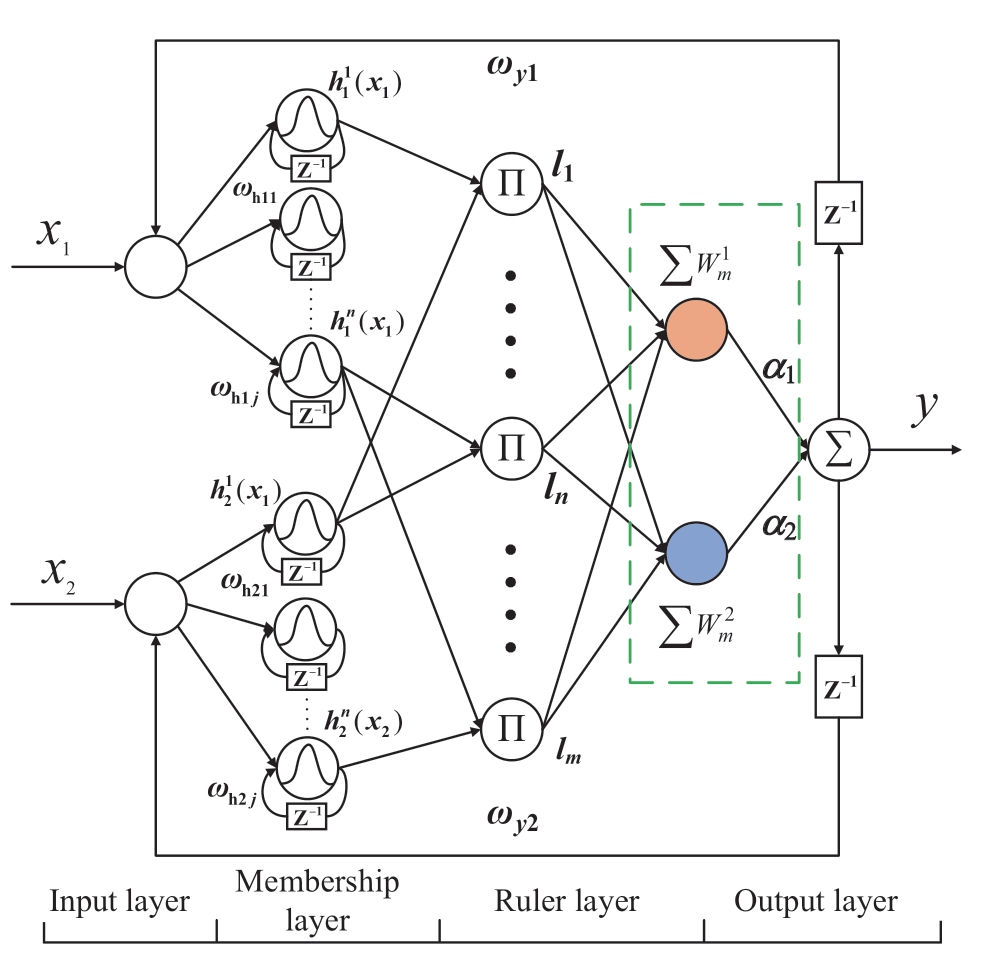
Fig.6 Structure diagram of double-loop recurrent fuzzy neural network
In this study,sdq0 serves as the input signal xi (i=1,2,...,n) as well as the feedback signal of the last output layer and is conveyed to the membership layer.The relationship between the input and output of this layer is expressed as follows:
where xi and µi are the ith input and output respectively;ωyi is the recursive weight of the output layer;and y(n-1) is the output from the previous sampling time.
A Gaussian function is adopted as the activation function on each node in the membership layer,and the output of the jth node can be expressed as

where ωhij is the internal feedback weight of the corresponding membership layer;μi(n-1) is the output signal of the previous sampling time in the membership layer;and cij and bij are the central vector and Gaussian function width of the membership layer,respectively.
The formulas for the rule and output layers are the same as those for a conventional FNN.Therefore,as shown in Fig.6,the output of the DRFNN is expressed as
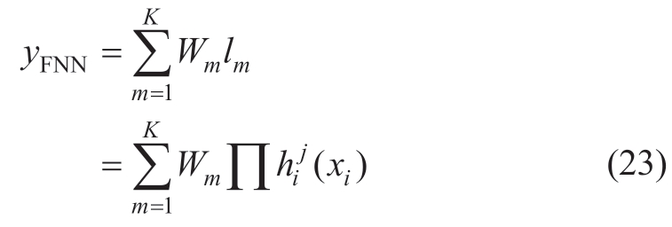
where Wm is the connection weight between the output layer and rule layer;l is equal to Πh(xi);K is the number of hidden layers;yFNN is the output signal of the FNN,i.e.,the actual value ![]() of F(x).
of F(x).
The output-weight law of the DRFNN can be expressed as
where η1 indicates the learning rate of the weights.
As shown in (24),the output-weight W adaptive law of the classical DRFNN is only related to the sliding-mode surface s,whereas the integral term for the sliding-mode surface results in a significant transient impact before stability is achieved.Therefore,the DRFNN structure is improved in this study.A weight W2 related to the current error e is added between the hidden and output layers,as indicated by the dotted box in Fig.6.Two different weight adaptive laws are used to obtain a new output value to improve the operational efficiency of the neural network and reduce the impulse current before power stabilization.
The two weight adaptive laws of the output are design as follows:

Thus,the output of the improved DRFNN (IDRFNN)can be rewritten as
where α1 and α2 are the adaptive weights.
The adaptive parameters and weight laws of the IDRFNN can be expressed as
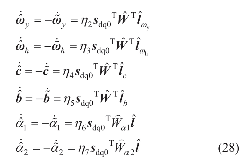
where η2,η3,η4,η5,η6,and η7 indicate the learning rates of the corresponding parameters and weights.
The system stability and parameter convergence can be verified using the Lyapunov stability theory.The slidingmode surface converged to approximately zero within finite time.For a detailed analysis and proof,please refer to Appendix A,Proof 2.
The output yFNN of the FNN is assumed to approach F(x)online.Additionally,yFNN is introduced into (20) to derive the output uFNN of the IDRFNN.
As shown in (29),compared with the classical control law of SMC expressed in (20),the output of the IDRFNN approximates F(x) adaptively.This adaptation reduces the reliance on parameters such as the bridge arm resistance RH and phase angle ω,thus ultimately improving the system stability.
2.4 Quasi-continuous second-order sliding-mode controller design
Although the FNN SMC effectively mitigates chattering,the gain λ must be larger than the upper bound of the lumped uncertainty to satisfy the Lyapunov stability condition,as shown in Section 3.2.However,the upper bound of lumped uncertainty in practical applications is unknown.An excessively high gain may increase buffeting,thus adversely affecting the control accuracy and stability.Hence,a quasicontinuous second-order SMC is designed to compensate for the approximation error of the IDRFNN and mitigate the chattering problem resulting from excessive gain.The control law expressed in (29) can be rewritten as follows:
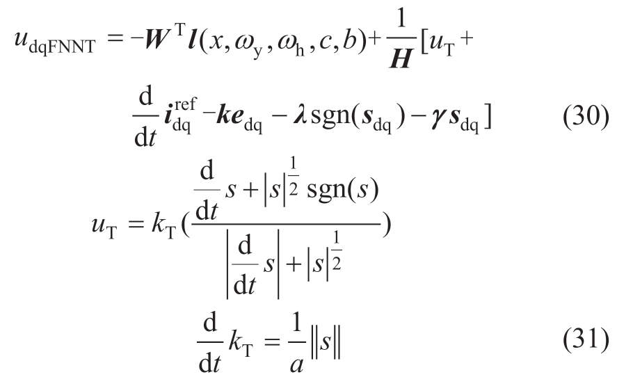
where kT > 0 is the gain of the second-order sliding mode.
The stability analysis is presented in Appendix A,Proof 3.As shown in (A17),when the λ of the sliding-mode reaching law is exceedingly large,thus resulting in larger s values,the quasi-continuous second-order sliding-mode controller will reduce the equivalent gain λ′=λ -kT,where kT is adaptively determined.This adjustment maintains the system stability and further alleviates chattering.
2.5 Calculus SMC design
Two main approaches exist for suppressing the ground fault current: current arc suppression and voltage arc suppression.Compared with the voltage arc-suppression method,the current arc-suppression method offers faster response and is more effective in addressing low-resistance ground faults that pose significant harm,thus rendering it widely used.Unlike the dq-axis current reference value,the 0-axis current reference value is sinusoidal,which results in significant steady-state errors and unsatisfactory monitoring performance when the FMS adopts PI control for current arc suppression [14].To enhance the overall effect of arc suppression,an IDRFNN sliding mode controller based on the calculus sliding-mode surface is proposed to monitor the reference current as follows:
Based on (8),![]() and iz0 can be regarded as sine waves when the distribution networks are in three-phase balance;hence,they can be expressed as
and iz0 can be regarded as sine waves when the distribution networks are in three-phase balance;hence,they can be expressed as
where I0m and φ are the amplitude and phase of the 0-axis reference current,respectively;and ΔI0m and Δφ are the errors of amplitude and phase monitoring respectively,which are assumed to be constants.Meanwhile,the monitoring error of the phase angle ω is disregarded.
Using the second-order derivatives of (32) and (33),the second derivative of e0 can be expressed as

The second derivative of e0 is obtained from Equation(34).According to (17),k10≠0 can be set.The calculus sliding-mode surface is calculated as follows:
Compared with the case of the integral sliding-mode surface,the introduction of differential terms renders the controller more sensitive to error changes and causes it to begin adjusting the control input before the actual error occurs,thereby improving the response speed.
Similarly,the output of the control system on the 0-axis can be expressed as

where G(x)=-RHiz0/2-us0;L=Lstat+LH/2;and λ0 > 0 and γ0 > 0 are the gains of the sign function and sliding-mode surface,respectively.
The stability on the 0-axis can be verified using the Lyapunov theory.The IDRFNN is used to approximate G(x),and the quasi-continuous second-order SMC is used to reduce the approximation error;thus,(36) can be rewritten as
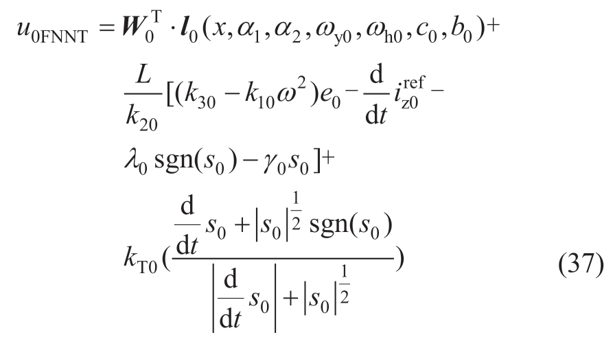
where d/dt(kT0)=‖s0‖/a0;W0,α1,α2,ωy0,ωh0,c0,and b0 are the internal parameters and weights of the IDRFNN,whose adaptive laws are the same as those shown in (28);and kT0 >0 is the 0-axis gain in the second-order sliding mode.
3 Simulation analysis
3.1 Simulation design
To verify the effectiveness of the proposed control strategy,a 10 kV distribution network model with a three-port FMS was developed in MATLAB/Simulink.Simulations were conducted to assess the power interaction and arc-suppression capability under SPG faults.Ports 1 and 2 of the FMS were operated in the P-Q mode,whereas port 3 was operated in the udc-Q mode.Assuming threephase balance,the parameters of the flexible interconnected distribution networks are as listed in Table B1 of Appendix B.The proposed strategy was simulated under various operating conditions,and a comparison was performed between the improved global fast terminal SMC method from [21] and the RBFNN SMC method from [22].The model parameters of the three controllers are listed in Tables B2,B3,and B4 of Appendix B.
3.2 Comparative analysis of steady-state response during power interaction
The DC-link capacitor was precharged until its voltage reached 20 kV.When the FMS engaged in multiterminal power interaction,port 1 began transmitting 8 MW of active power and 2 MVAR of reactive power to feeder 1 at 0.05 s.The steady-state response waveforms of the active and reactive powers of the FMS at port 1 for the three control methods are shown in Fig.7.
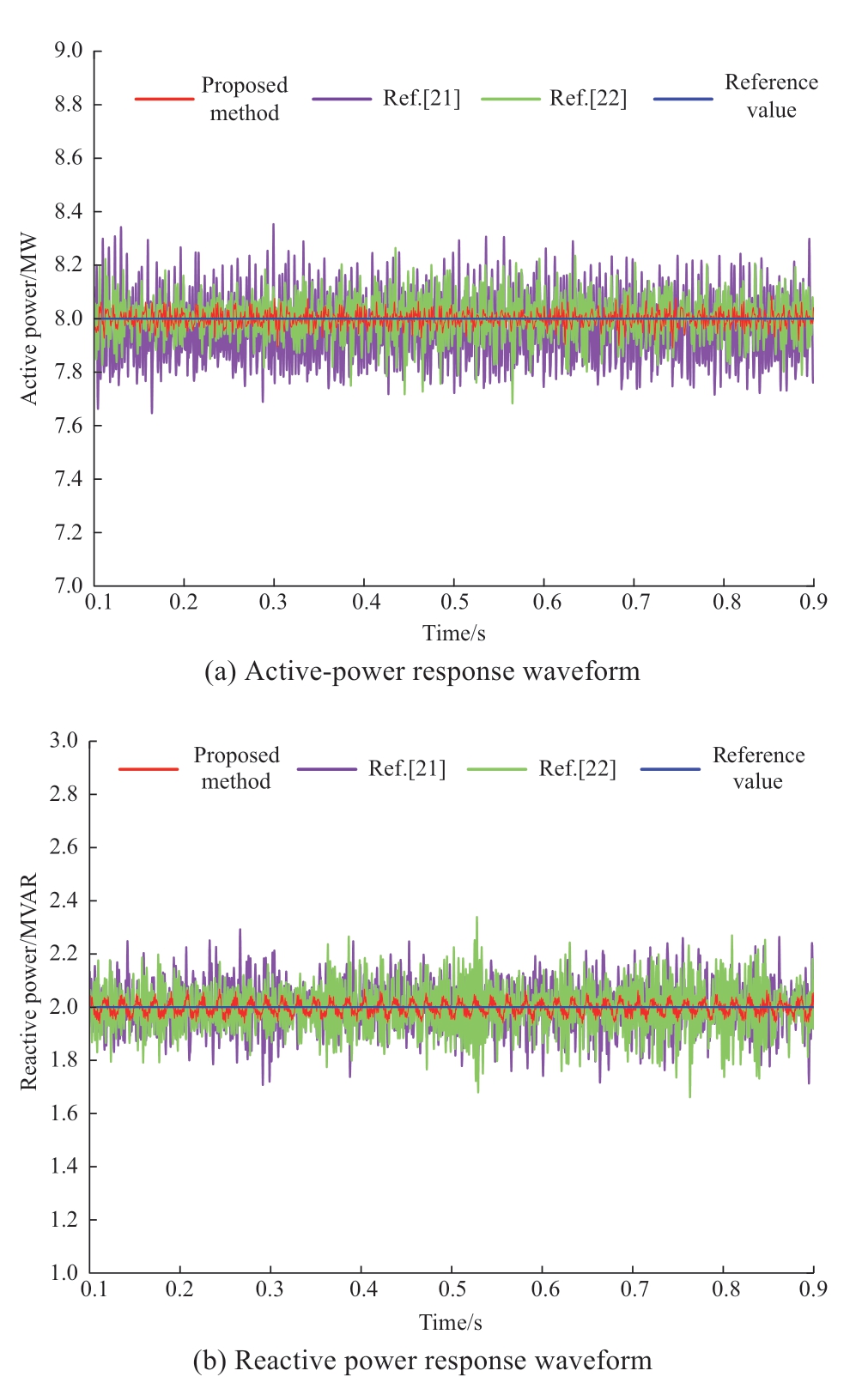
Fig.7 Power steady state response waveform
To evaluate the different control approaches in terms of power fluctuations,the fluctuation ratio (FR) is expressed as
where ![]() are the maximum and minimum values,respectively,of the actual active (or reactive)output power,and
are the maximum and minimum values,respectively,of the actual active (or reactive)output power,and ![]() is the active (or reactive) power reference value.
is the active (or reactive) power reference value.
In the steady state,the FRP of the three proposed methods [21] and [22] was 2.13%,7.63%,and 5.63%,whereas the FRQ was 5.5%,20.1%,and 23.5%.Larger power-response fluctuations increased the harmonic content of the AC current,thus affecting the power quality of the distribution networks.Thus,the Fourier harmonic analysis conducted on the A-phase current at port 1,as depicted in Fig.8,revealed that the total harmonic distortions (THDs)for the three control methods were 0.47%,3.03%,and 1.33%.A clear trend was observed,i.e.,a smaller THD corresponded to a lower even-harmonic content.Therefore,compared with the other two approaches,the IDRFNN SMC is a better method that effectively mitigates power response fluctuations and minimizes the current harmonic content,thus improving the power quality and reducing network losses.
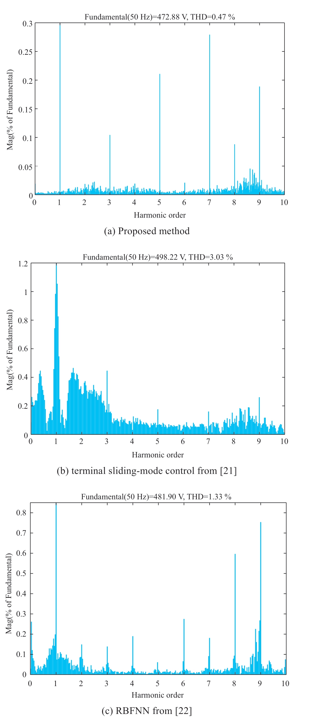
Fig.8 THD of A-phase current under different control strategies
3.3 Comparative analysis of dynamic response during power interaction
To compare the dynamic performance of the controller,the d-axis current (per unit value) on the AC side of port 1 and the DC voltage waveform were selected for analysis,as shown in Figs.9 and 10.An SPG fault occurred in feeder 1 at 0.1 s.The FMS injected a 0-axis current for arc suppression at 0.16 s.The three-phase inductance on the AC side decreased abruptly to 2/3 of the rated value at 0.25 s.
As shown in Fig.9,when SPG faults and inductance perturbations occurred,the improved global terminal SMC from [21] adopted a new reaching law and slidingmode surface,thus resulting in a relatively less transient impact;however,the oscillation time remained long.Additionally,the current oscillations increased following the inductance perturbation.The RBFNN SMC proposed in [22] exhibited a relatively simple structure,thus resulting in significant transient oscillations at the moment of faults,with fluctuations intensifying after parameter perturbation.Conversely,the transient impulse current and oscillation time of the proposed control method in this paper were minimal.Even after parameter perturbation occurred,the IDRFNN SMC maintained its accurate monitoring and minimal current oscillations owing to its strong online learning and adaptive capabilities.As shown in Fig.10,the proposed method effectively stabilized the DC voltage at 20 kV with reduced fluctuations.Its transient performance,stability,and robustness against parameter perturbations surpassed those of the other two methods.
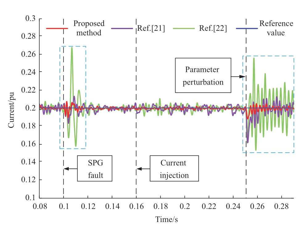
Fig.9 D-axis current dynamic response waveforms of three methods
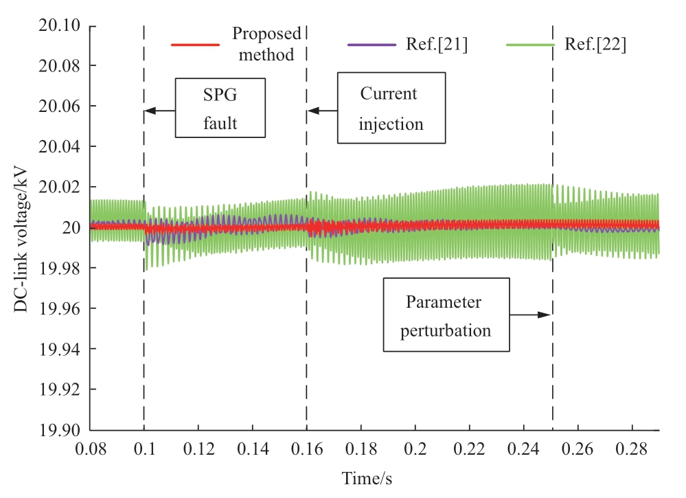
Fig.10 DC-link voltage response waveforms of three methods
To provide further evidence regarding the dynamic capabilities of the enhanced DRFNN SMC,Fig.11 shows its response to an abrupt increase in the active power.Specifically,at 1 s,the active-power reference value decreased from 8 to 6 MW.Comparing the FNN from [23]and the DRFNN from [24] with the proposed IDRFNN method,the latter significantly mitigated both the transient shock and the transition process of the power following the incorporation of error weights.Notably,this advancement was achieved without compromising the monitoring speed or stability,thereby elevating the overall transient performance.
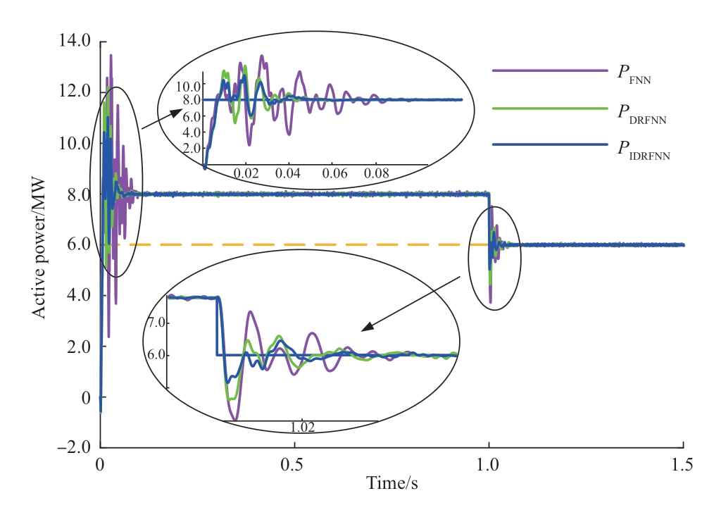
Fig.11 Active power response waveforms under different FNN control methods
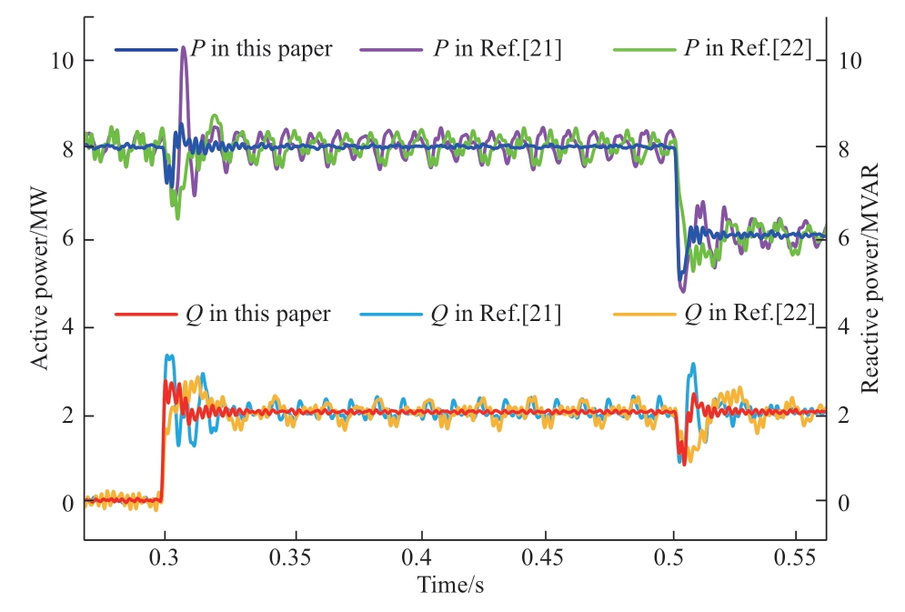
Fig.12 Active and reactive power response during power step
In the rotating dq0-axis coordinate system,a step change in one axis triggers overmodulation during the transient overshoot period,which subsequently induces nonlinear distortions across other axes and ultimately compromises the power quality.Figure 12 shows the dynamic waveforms of both the active and reactive power responses during a power-step change.Compared with the terminal SMC from [21] and the RBFNN from [22],the improved DRFNN exhibited superior performance when step changes occurred in the active (or reactive) power reference values.Specifically,it not only attained a steady state more rapidly with minimized transient disturbances but also effectively stabilized fluctuations in the reactive (or active) power.This underscores its remarkable robustness and rapid responsiveness under dynamic system conditions.
Fig.13 shows the variation in kT,which is the gain of the quasi-continuous second-order sliding-mode controller,when the gain of the sign function λ was 5 and 25.During steady-state operation of the system,kT increased gradually.When λ=25,the transient oscillation time for approaching the sliding-mode surface was longer,thus resulting in a longer period for the stabilization of kT.Once the system reached steady state,kT remained almost constant.When an SPG fault occurred in feeder 1 at 0.15 s,kT was adjusted automatically and remained fixed at that value.After the initiation of arc suppression by the controller at 0.2 s,kT remained unchanged.When inductance perturbation occurred at 0.25 s,the adjustment of kT continued and then halted at a fixed value.This shows that kT adapts dynamically to the changing system conditions.Fig.14 shows the d-axis current waveform when λ was set to 25.Without the addition of QS-SMC compensation,the d-axis current exhibited significant oscillations,and the system became unstable after the inductance perturbation.However,when QS-SMC compensation was included,kT increased adaptively to reduce the equivalent gain (λ′=λ -kT),thereby mitigating the oscillations in the control signal and ensuring system stability.
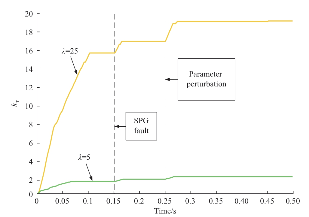
Fig.13 Adaptive change of kT during control process
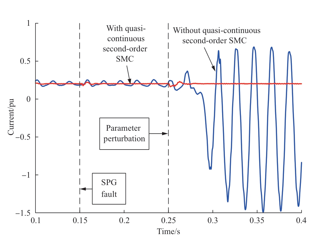
Fig.14 D-axis current waveform when λ was set to an extremely large value
3.4 Analysis of flexible arc-suppression ability
An A-phase grounding fault occurred in feeder 1 at 0.1 s.The FMS output a 0-axis current to the fault end and fully compensated for the ground current at 0.16 s.The active power reference value of port 1 underwent a step change at 0.22 s.Fig.15 shows the dynamic waveforms of the SPG fault currents under various fault resistances: 1 Ω represents a metallic ground fault,10 Ω a low-resistance ground fault,100 Ω a medium-resistance ground fault,and 3000 Ω a high-resistance ground fault [27].As shown in the figure,the higher the grounding resistance,the smaller is the amplitude of the grounding current and the lower is the arcsuppression speed.After the injection of a 0-axis current,the residual current at the ground point was reduced to less than 2A,thus effectively achieving reliable arc suppression.Furthermore,when the power jump changed,the arcsuppression performance remained stable.This shows that the FMS can effectively achieve the decoupling control of the active power,reactive-power interaction,and arc suppression.
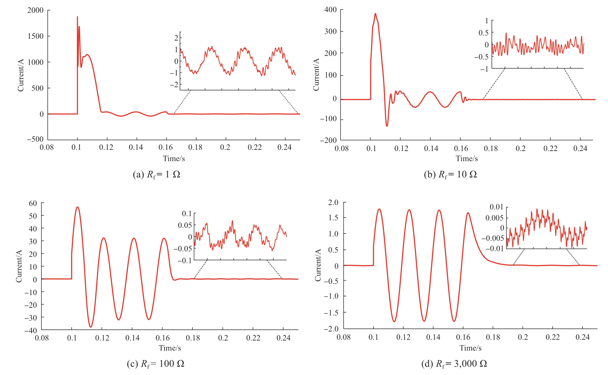
Fig.15 Ground currents based on different transition resistors
The fault-current rejection rate [28],abbreviated as FCRR,is used to assess the arc-suppression performance of the different control methods.The FCRR can be expressed as
where ![]() is the root-mean-square value of the fault current,and
is the root-mean-square value of the fault current,and ![]() is the root-mean-square value of the fault current after the injection of the 0-axis current.
is the root-mean-square value of the fault current after the injection of the 0-axis current.
In addition to the methods proposed in [21] and [22],the PI-control-applied flexible arc suppression in [13] is supplemented to compare the arc-suppression performance.Their fault-current-suppression performance under different ground resistances is presented in Table 1.Zhang et al. of[13] and Feng et al. of [22] relied solely on the proportion and integral terms,thus resulting in a larger steady-state error and a lower FCRR compared with those of this study.The method proposed in [21] aimed for a robust and rapid response at the expense of the control accuracy.
Table 1 Comparison of arc suppression for various control methods
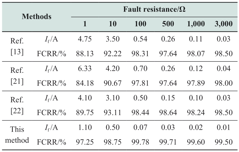
When the fault resistance was 1 Ω,the residual current exceeded 5 A,thus resulting in arc-suppression failure.The proposed method exhibited high monitoring accuracy for both metallic ground and high-resistance ground faults.It effectively reduced the fault current to below 2 A,thus ensuring reliable arc suppression,and its FCRR was superior to those of the other three control methods.
To verify the arc-suppression effect of the FMS in the case of double-ended grounding faults,SPG faults were generated on two feeder lines of the flexible interconnection at 0.05 and 0.25 s with both fault resistances set at 100 Ω.Arc suppression was initiated at 0.11 and 0.31 s.The waveforms of the double-ended grounding currents are presented in Fig.16.The performance of double-ended current elimination under different ground resistances is presented in Table 2.As shown in Fig.16 and Table 2,the FMS maintained a superior arc-suppression rate under double-ended ground faults,and the two ends did not affect each other.
Table 2 Residual current at different ground resistances when two-terminal grounding fault occurred
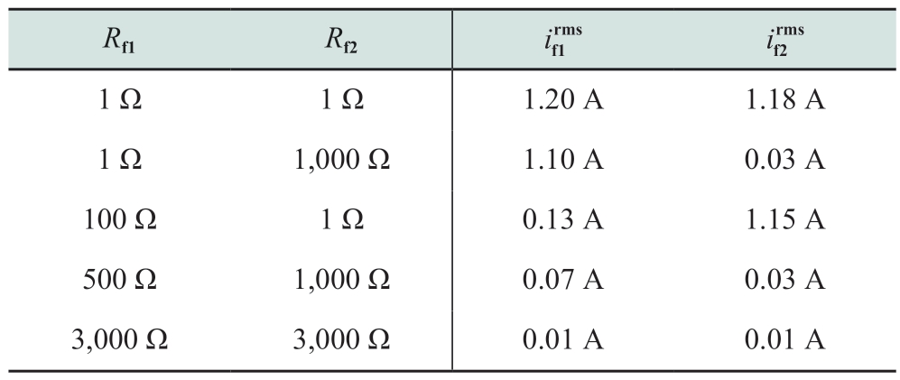
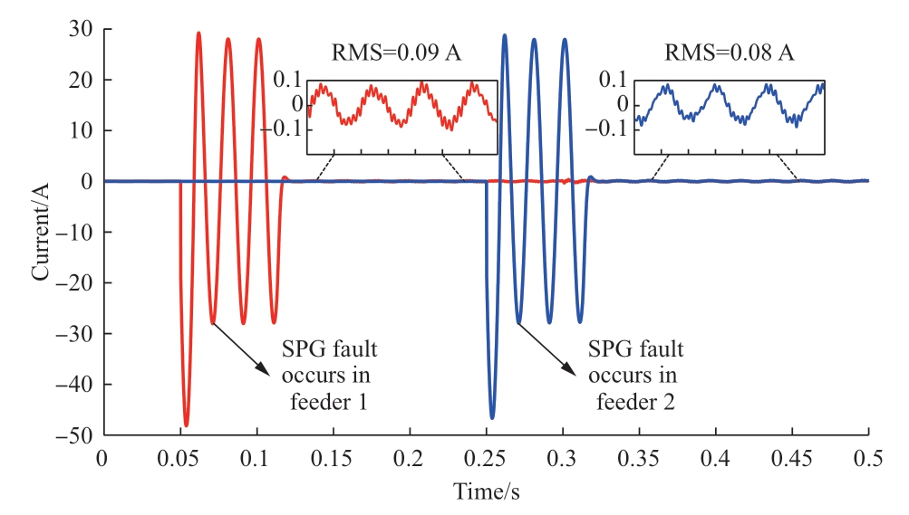
Fig.16 Ground current waveforms after double-ended grounding faults
As shown in Fig.15,the arc-suppression speed of the leakage current decreased as the fault resistance increased.To illustrate the swiftness of the proposed control strategy in flexible arc suppression,the fault-current waveform of the proposed method was compared with those of [13],[21],and [22].This comparison,as depicted in Fig.17,focuses on scenarios with a fault resistance of 3,000 Ω.In this case,an SPG fault occurred in feeder 1 at 0.1 s,and the FMS initiated a full compensation current at 0.16 s.Among the four control techniques considered—PI control from[13],the improved global fast terminal SMC from [21],the RBFNN SMC from [22],and the improved DRFNN SMC introduced in this study—the arc-suppression speeds varied considerably.Specifically,the arc-suppression times to reach stability were 0.17,0.12,0.09,and 0.06 s,respectively.The PI control method relies on a substantial proportional coefficient to achieve arc suppression,which results in excessive momentary shocks during current injection.Owing to its distinct sliding-mode surface and reaching law,the improved global fast terminal SMC achieved faster arc suppression.However,this deteriorated the monitoring accuracy,thus resulting in a larger residual current.The RBFNN SMC approach accelerates arc suppression through an online approximation by leveraging a neural network.The innovative method proposed herein,which integrates the calculus sliding mode with the adaptive control of the DRFNN,not only maintains a robust fault-current elimination rate but also significantly increases the arc-suppression speed.This hybrid approach combines the strengths of both slidingmode theory and neural network-based adaptation,thus offering a comprehensive solution to the challenges posed by arc suppression in power systems.
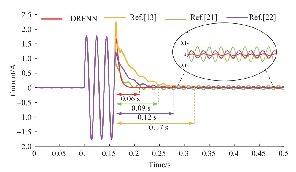
Fig.17 Ground current under various methods with Rf=3,000 Ω
4 Conclusion
The rapid development of renewable energy has increased the proportion of DG in distribution networks,thereby exacerbating the problems of power flow,load imbalance,and SPG faults.Therefore,FMSs must be applied to achieve the multifunctional operation of power interaction across various feeders and flexible arc suppression.To address the limitations of the classical FMS control,an improved DRFNN sliding-mode controller with a calculus sliding-mode surface was designed.Compared with classical control methods,this controller comprehensively considers the practical implications of lumped uncertainty,parameter perturbation,and ground faults.It reduces the reliance on precise system models,thus offering improvements in robustness,accuracy,and speed.In addition,it features a high arc-suppression rate,thereby satisfying the requirements for reliable arc suppression.The proposed strategy effectively mitigates the effects of disturbances encountered in practical applications.It not only increases the power quality but also reinforces the stability and security of the distribution network system.Additionally,by seamlessly integrating the flexible arc-suppression functionality into the FMS,it further optimizes the economic efficiency and utilization of device operations.
Nevertheless,the proposed controller encompasses a multitude of control parameters if the FMS system is not optimized.Hence,future research efforts should prioritize system optimization and delve into more comprehensive system designs and control parameter self-tuning.In addition,better experimental conditions must be established to verify the method on an experimental platform.
Appendix A
Proof 1
Define the Lyapunov function as V=s Ts/2 ≥ 0.Combining(19) and (20),its derivative can be expressed as follows:

This implies that when the gain λ is greater than the upper bound of the lumped uncertainty Dmax,F(x) is always less than 0.Therefore,based on the Lyapunov stability criterion,one can prove that the state variables converge to zero along the sliding-mode surface in finite time,and that this control is asymptotically stable.Proof completed.
Theorem: For the inequation dV/dt ≤ -βV+f,∀t ≥ t0≥ 0,one can obtain
where β > 0.
When λ is greater than the D of the disturbance,(A1)satisfies the following relation:

Based on the theorem above,let β= and f=0;therefore,the solution is
V(t) can exponentially converge to zero and the speed is positively related to  .The greater the value of the sliding-mode surface s,the higher is the convergence rate.Simultaneously,the introduction of the symbolic function λsgn(·) allows for a smooth speed λ as s approaches zero,thus ensuring that the control signal reaches the slidingmode surface smoothly.Consequently,during parameter design,large
  values and small λ values should be selected to improve the monitoring speed and reduce chattering.
Proof 2
To design the adaptive law for the IDRFNN and analyze its stability,we assume the existence of optimal weights (α1*,![]() central vectors c*,and Gaussian function widths b* to approximate F(x),i.e.,F*(x)=W*Tl*+ε,where ε is the minimum approximation error and l*=
central vectors c*,and Gaussian function widths b* to approximate F(x),i.e.,F*(x)=W*Tl*+ε,where ε is the minimum approximation error and l*=![]() c*,b*).
c*,b*).
The actual control law of the proposed IDRFNN is
where ![]() are the actual values of α1,α2,ωy,ωh,c,and b,respectively.
are the actual values of α1,α2,ωy,ωh,c,and b,respectively.
Thus,the approximation error can be expressed as
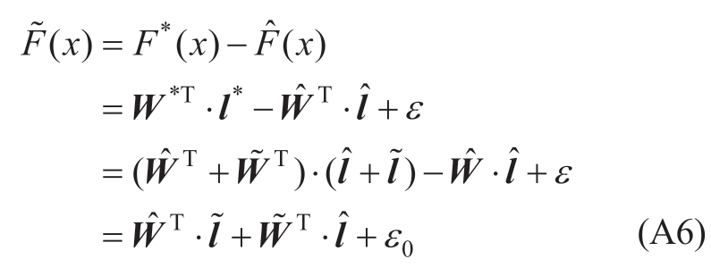
where  is the error of the output in the ruler layer.
Next, and
and  are expanded via the Taylor series for
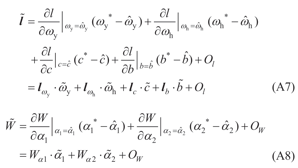
where Ol and OW are higher-order terms.The coefficient matrix is
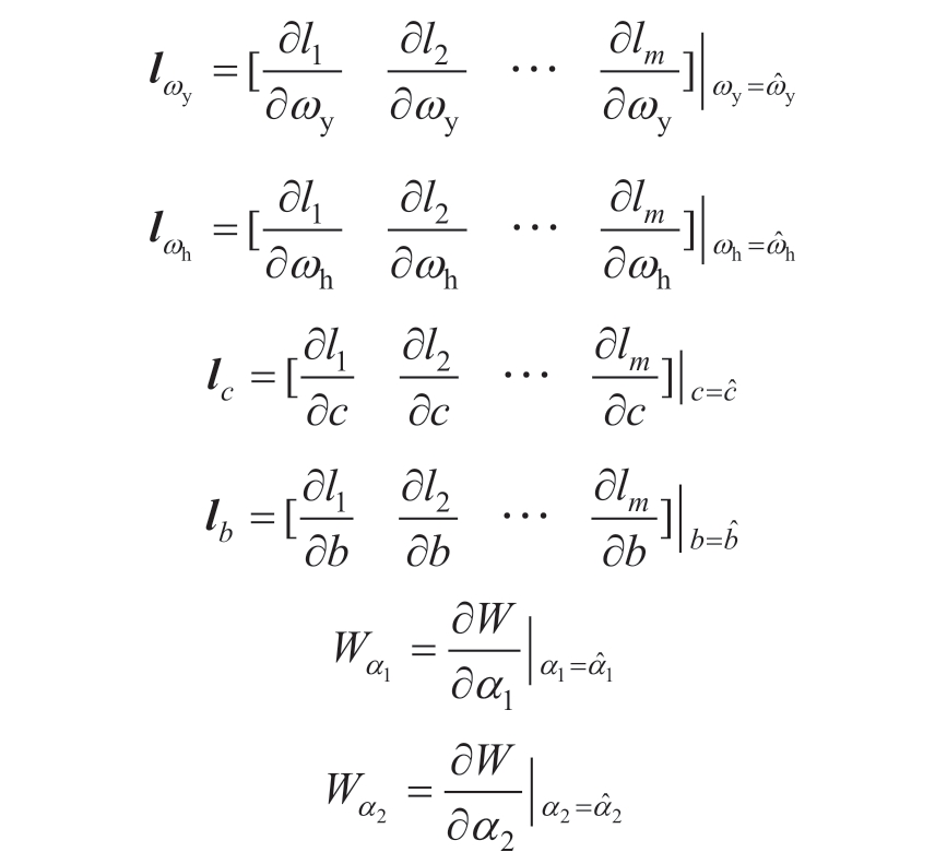
Substituting (A7-A8) into (A6), can be rewritten as
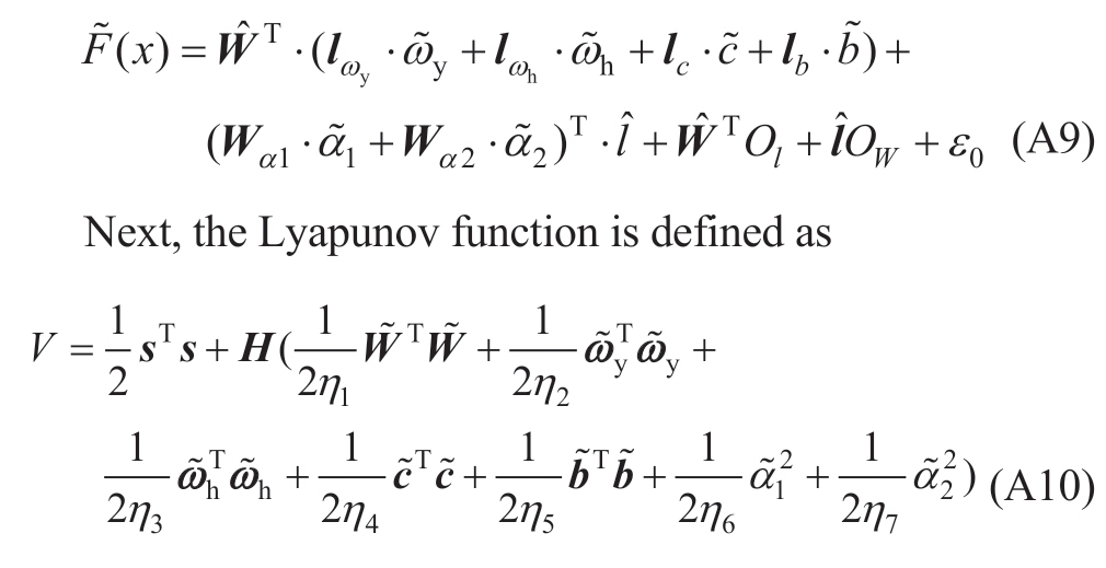
Combining the above with (19) and (29),the derivative of V can be obtained as follows:
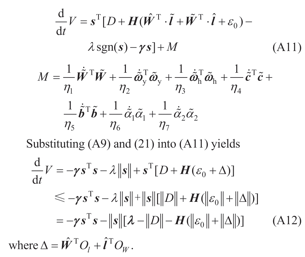
As the number of nodes in the neural network membership layer increases,the neural network approximation error gradually decreases.Thus,based on the assumption of lumped uncertainty,the following bounded condition exists:
In other words,when λ> H(ε0max+Δmax )+Dmax, ≤0 and
  /2≤0.Based on the Lyapunov stability theorem and Barbalat’s lemma,V˙ converges to zero when t→∞.This implies that both the neural-network approximation error and control-signal error asymptotically converge to zero.Proof completed.
Proof 3
The Lyapunov function is expressed as
Combining the above with (19),the derivative of V can be expressed as

Substituting (30) into (A14) yields as
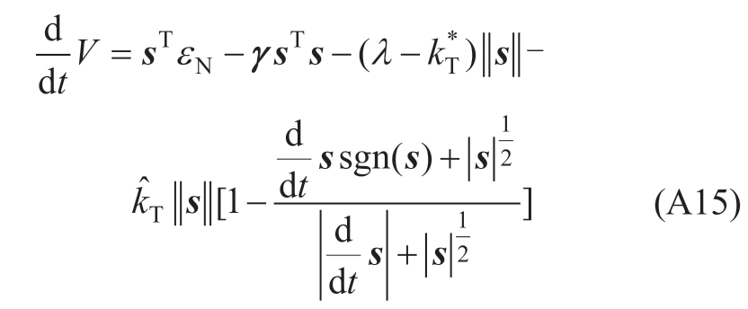
whereεN=D+H·  (x) represents the sum of the lumped uncertainty and neural-network approximation error;and
![]() are the optimal value,actual value,and error of the second-order sliding mode gain,respectively.
are the optimal value,actual value,and error of the second-order sliding mode gain,respectively.
One can easily prove that
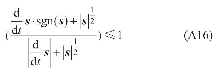
Thus,(A15) can be written as

Therefore,when![]() 0,dV/dt is less than 0.According to the Lyapunov stability theorem,the designed controller ensures that the error converges asymptotically to zero.Proof completed.
0,dV/dt is less than 0.According to the Lyapunov stability theorem,the designed controller ensures that the error converges asymptotically to zero.Proof completed.
Appendix B
Table B1 Simulation parameters of distribution network and FMS
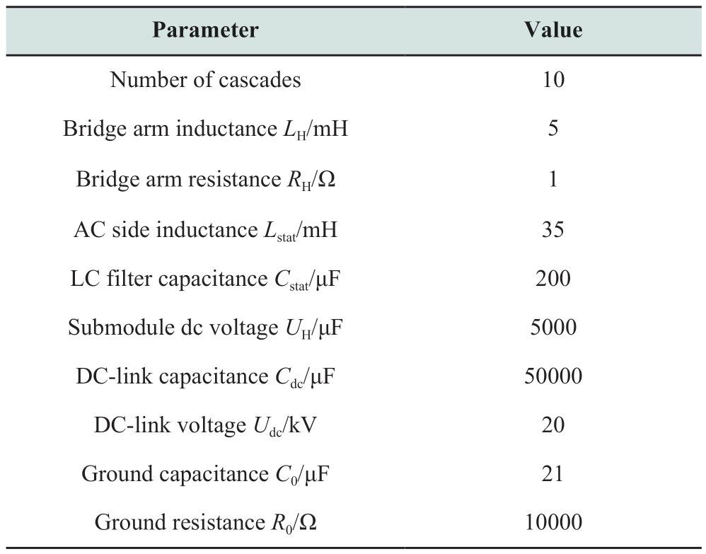
Table B2 Parameters of improved DRFNN sliding-mode controller
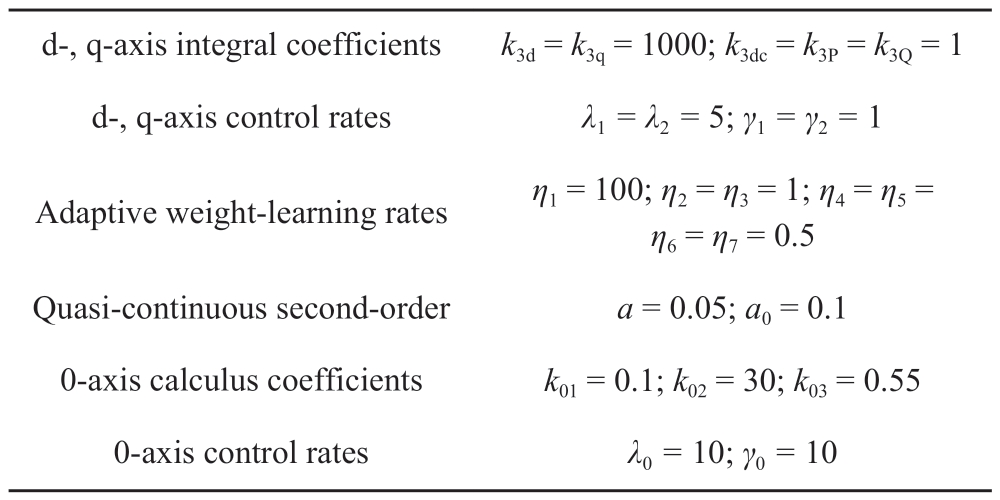
Table B3 Parameters of improved global fast terminal sliding-mode controller

Table B4 Parameters of RBFNN sliding-mode control

Acknowledgments
The authors thank the Natural Science Foundation of Fujian,China (No.2021J01633).
Declaration of Competing Interest
The authors declare no conflict of interest.
References
[1] Ouyang S D,Liu J J,Yang Y,et al.(2020) DC voltage control strategy of three-terminal medium-voltage power electronic transformer-based soft normally open points.IEEE Transactions on Industrial Electronics,67(5): 3684-3695
[2] Zhou N C,Tao A Q,Wang J,et al.(2023) Coordinated allocation of soft open point and converter-based energy storage systems in PV penetrated active distribution networks.IET Renewable Power Generation,17(2): 400-412
[3] Gao W,He W X,Wai R J,et al.(2024) High-impedance arc fault modeling for distribution networks based on dynamic geometry dimension.Electric Power Systems Research,229: 110109
[4] Ji H R,Wang C S,Li P,et al.(2017) An enhanced SOCP-based method for feeder load balancing using the multi-terminal soft open point in active distribution networks.Applied Energy,208:986-995
[5] Colak I,Bayindir R,Sagiroglu S (2020) The effects of the smart grid system on the national grids.2020 8th International Conference on Smart Grid (icSmartGrid).Paris,France.IEEE,:122-126
[6] Li P,Ji H R,Wang C S,et al.(2017) Coordinated control method of voltage and reactive power for active distribution networks based on soft open point.IEEE Transactions on Sustainable Energy,8(4): 1430-1442
[7] Cong P W,Hu Z C,Tang W,et al.(2019) Optimal allocation of soft open points in distribution networks based on candidate location opitimization.8th Renewable Power Generation Conference (RPG 2019).Shanghai,China.London: IET,: 1-6
[8] You R,Lu X N (2022) Voltage unbalance compensation in distribution feeders using soft open points.Journal of Modern Power Systems and Clean Energy,10(4): 1000-1008
[9] Yang Z C,Yang F,Min H D,et al.(2023) A local control strategy for voltage fluctuation suppression in a flexible interconnected distribution station area based on soft open point.Sustainability,15(5): 4424
[10] Wang Z Q,Zhou H Y,Huo Q H,et al.(2022) Three-vector-based low complexity model predictive control for soft open point.Mathematical Problems in Engineering,2022: 1526676
[11] Li B K,Liang Y S,Wang G,et al.(2020) A control strategy for soft open points based on adaptive voltage droop outerloop control and sliding mode inner-loop control with feedback linearization.International Journal of Electrical Power &Energy Systems,122: 106205
[12] Huang W T,Gao C Z,Li R,et al.(2024) A model predictive control-based voltage optimization method for highway transportation power supply networks with soft open points.IEEE Transactions on Industry Applications,60(1): 1141-1150
[13] Zhang B L,Guo M F,Zheng Z Y,et al.(2023) Fault current limitation with energy recovery based on power electronics in hybrid AC-DC active distribution networks.IEEE Transactions on Power Electronics,38(10): 12593-12606
[14] Fan B S,Zheng N,Zeng X J,et al.(2023) A comparative investigation of flexible arc suppression devices in distribution network.IET Power Electronics,16(3): 498-518
[15] Tu C M,Jia W H,Guo Q,et al.(2022) UPQC optimal operation for transient-and steady-state coordinated regulation of grounding fault in distribution network.Power System Technology,46(05):1810-1819
[16] Zhang B L,Guo M F,Zheng Z Y,et al.(2023) A novel method for simultaneous power compensation and ground fault elimination in distribution networks.CSEE Journal of Power and Energy Systems,(99): 1-12
[17] Wang Z,Fei J T (2022) Fractional-order terminal sliding-mode control using self-evolving recurrent Chebyshev fuzzy neural network for MEMS gyroscope.IEEE Transactions on Fuzzy Systems,30(7): 2747-2758
[18] Hou S X,Wang C,Chu Y D,et al.(2022) Neural-observer-based terminal sliding mode control: Design and application.IEEE Transactions on Fuzzy Systems,30(11): 4800-4814
[19] Ding S H,Hou Q K,Wang H (2023) Disturbance-observer-based second-order sliding mode controller for speed control of PMSM drives.IEEE Transactions on Energy Conversion,38(1): 100-110
[20] Chen X G,Li Y M,Ma H F,et al.(2021) A novel variable exponential discrete time sliding mode reaching law.IEEE Transactions on Circuits and Systems Ⅱ: Express Briefs,68(7):2518-2522
[21] Pan H H,Zhang G M,Ouyang H M,et al.(2020) A novel global fast terminal sliding mode control scheme for second-order systems.IEEE Access,8: 22758-22769
[22] Feng H,Song Q Y,Ma S L,et al.(2022) A new adaptive sliding mode controller based on the RBF neural network for an electrohydraulic servo system.ISA Transactions,129(Pt A): 472-484
[23] Yang Y,Wai R J (1832) Design of adaptive fuzzy-neuralnetwork-imitating sliding-mode control for parallel-inverter system in islanded micro-grid.IEEE Access,9: 56376-56396
[24] Fei J T,Wang Z,Liang X,et al.(2022) Fractional sliding-mode control for microgyroscope based on multilayer recurrent fuzzy neural network.IEEE Transactions on Fuzzy Systems,30(6):1712-1721
[25] Fei J T,Lu C (2018) Adaptive sliding mode control of dynamic systems using double loop recurrent neural network structure.IEEE Transactions on Neural Networks and Learning Systems,29(4): 1275-1286
[26] Bao G,Zeng Z G,Shen Y J (2018) Region stability analysis and tracking control of memristive recurrent neural network.Neural Networks,98: 51-58
[27] Liu M X,Zhang C,Liu K L (2021) Simulation and experiment analysis of 10 kV flexible grounding device.Information,12(9):384
[28] Mostafa B,Ma-apel M,Barik,et al.(2022) Control of arc suppression devices in compensated power distribution systems using an integral sliding mode controller for mitigating powerline bushfires.International Journal of Electrical Power &Energy Systems,134: 107481

Scan for more details
Received:30 October 2023/Revised: 29 January 2024/Accepted:7 February 2024/Published: 25 April 2024
 Wei Gao
gaowei0203@fzu.edu.cn
Jianghua Liao
1354324882@qq.com
Yan Yang
yangyan@hyit.edu.cn
Gengjie Yang
ygj23802@fzu.edu.cn
2096-5117/© 2024 Global Energy Interconnection Development and Cooperation Organization.Production and hosting by Elsevier B.V.on behalf of KeAi Communications Co.,Ltd.This is an open access article under the CC BY-NC-ND license (http://creativecommons.org/licenses/by-nc-nd/4.0/).
Biographies

Jianghua Liao received the B.E.E degree at Fuzhou University,Fuzhou,China,in 2021.He is currently pursuing a Master’s degree at Fuzhou University,Fuzhou,China.His research interests include fault flexible suppression technology of distribution networks.

Wei Gao received the B.S.and M.S.degrees at Fuzhou University,China,in 2005 and 2008,respectively,and the Ph.D.degree from the National Taiwan University of Science and Technology,Taiwan,in 2021.He is currently an Associate Professor and doctoral supervisor at Fuzhou University.His research area focuses primarily on the generation technology of photovoltaics and the faults diagnosis of power equipment.

Yan Yang received the M.S.degree from the China University of Mining and Technology,China,in 2009,and the Ph.D.degree from the National Taiwan University of Science and Technology,Taiwan,in 2022.She is a lecturer in the Department of Automation,Huaiyin Institute of Technology,China.Her research interests are smart microgrids and the intelligent control of power converters.

Gengjie Yang received the B.S.and M.S.degrees at Fuzhou University,Fuzhou,China,in 1985 and 1988,respectively.He is a Professor in Fuzhou University.His research interests include power system analysis and control.
(Editor Yanbo Wang)
