0 Introduction
The through-type cophase traction direct power supply system will become an important part of electrified railway transportation because it addresses the negative-sequence current and enhances power quality [1-3].The method of collecting currents through sliding contact between the powered bow and traction network adopted by the electrified railway results in more faults in the traction network than in the power line.Therefore,studies on the protection of traction network lines are vital [4].
Currently,the traveling wave dominates in protecting a line in an AC/DC system,including single-terminal and twoterminal protection.In addition,single-terminal protection applies the line boundary of the DC power transmission system to form the protection scheme [5-7],whereas twoterminal protection utilizes the transient and traveling wave principles to form the scheme as the key point of research[8].In [9],a longitudinal scheme for protecting a multiterminal flexible DC grid based on the transient mutation energy was obtained through an analysis of the reflection and refraction wave regularity of the fault-traveling waves at the end of the line.In [10,11],the distinction between the transient current waveform on both sides of a line was highlighted by morphological filtering and Spearman’s rank correlation coefficient to shape the longitudinal scheme to protect DC and new energy transmission lines.In [12],the S-transform verification line boundary was used to respond to fault traveling waves under the tuned frequency with total reflection,and the energy ratio of the backward traveling wave tuning frequency to the forward frequency was used to identify the faults in and out of the line.Based on this,a longitudinal protection principle for HVDC transmission lines was established.Because traveling waves exhibit high speed,strong resistance to transition resistance,and non-interference with traditional operation,the protection for traction network traveling can be conducted more extensively based on the traditional distance protection for the traction power supply system.Under this connection,a new scheme [13] to protect the traction network line of a through-type cophase traction power supply system [14-16] was introduced appropriately [17].
Distance protection,a conventional approach relying on distance measurement,is commonly employed for safeguarding traction network lines in power supply systems.However,traditional schemes for traction network line protection are affected by fault resistance,large errors,and low precision.This paper proposes a longitudinal protection scheme for through-type same-phase direct power supply traction networks.Based on the current change rate,which reflects the stability of the system,this paper proposes the use of the empirical wavelet transform (EWT) to process the fault signal and extract high-frequency energy.Based on the ratio of the high-frequency transient energy on both sides of the boundary,the fault is determined to be inside or outside the region.The accuracy of the boundary attenuation was verified.
The analysis shows that the traction network line in the through-type cophase traction direct power supply system has a physical boundary that can weaken the high-frequency component of the fault signals.Consequently,an appreciable distinction exists in the high-frequency components of the fault signal between both sides of the boundary when faults occur inside the line.This implies that,if faults occur in the line,the high-frequency transient energy at both checkpoints detected on the line inside is larger than that detected at the checkpoints outside,and their ratio is large.However,if faults occur outside the line,the high-frequency transient energy at the detected checkpoints inside the line is smaller than that detected at the checkpoints outside,and the ratio is small.In this context,the EWT can be applied to extract the high-frequency transient energy of fault signals and launch a longitudinal scheme to protect the traction network.The simulation software PSCAD/EMTDC was used to conduct simulation verification by establishing a through-type cophase traction direct power-supply system model.The results demonstrate that this method is effective under various fault initial angles,distances to faults (DTFs),and fault transition resistances.
1 Basic principle
1.1 Structure of the through-type cophase traction direct power supply system
The structure of the through-type cophase traction direct power supply system is shown in Fig.1 (the positive direction of the current resembles that of a locomotive).The traction substation,which is essential to a power supply system,handles the symmetrical transformation technology of a pulse width modulation (PWM) three-phase rectifier and single-phase PWM inverter,both of which are under the control of a double closed-loop PI.Thus,it can prevent mutual interference between a public power network and the traction power supply system and enable transformation between the three-phase alternating current,direct current,and single-phase alternating current.The voltages on both sides of the traction network transform into the same phase,and the amplitude is used to eliminate electrical separation to supply power throughout the line.Parallel filters (L and C) at the traction substation exit can effectively filter harmonics to enhance the power quality.The symbols F1,F2,and F3 represent the locations where the faults occur.

Fig.1 Structural drawing of the through-type cophase traction direct power supply system
1.2 Frequency characteristics of the traction network boundary
The filters (L and C) at the traction substation exit can not only filter out the harmonics but also form the traction network boundary when they are parallel to the capacitance and a section of the traction network line.The transfer function G(jω) of the traction network boundary can be calculated using the line equivalent parameter in [18] and the boundary definition in [19].In Fig.2,load ZL represents the equivalent impedance of a section of the traction network line,and load ZC represents the equivalent impedance of the parallel capacitor at the traction substation exit.U2/U1 is designed to be a transfer function of the cophase traction direct power supply system on the traction network boundary.This is expressed as follows:
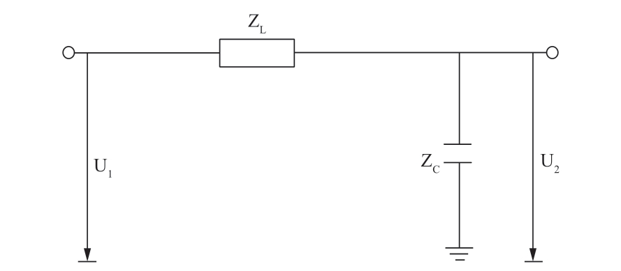
Fig.2 Schematic of direct traction power supply network boundary
Consequently,the Amplitude-frequency characteristic of G(j)ω,the transfer function of the traction network boundary in the direct power supply system mentioned above,can be expressed as follows:
In Fig.3,G(jω)≥1 when the signal’s frequency ranges from 0 to 550 Hz.However,G(jω)≤1 when the frequency is equal to or greater than 800 Hz and continues to decrease as the frequency increases.Hence,the parallel capacitance at the traction network line exit and boundary of a set of traction lines can dramatically weaken the frequency of the signals.
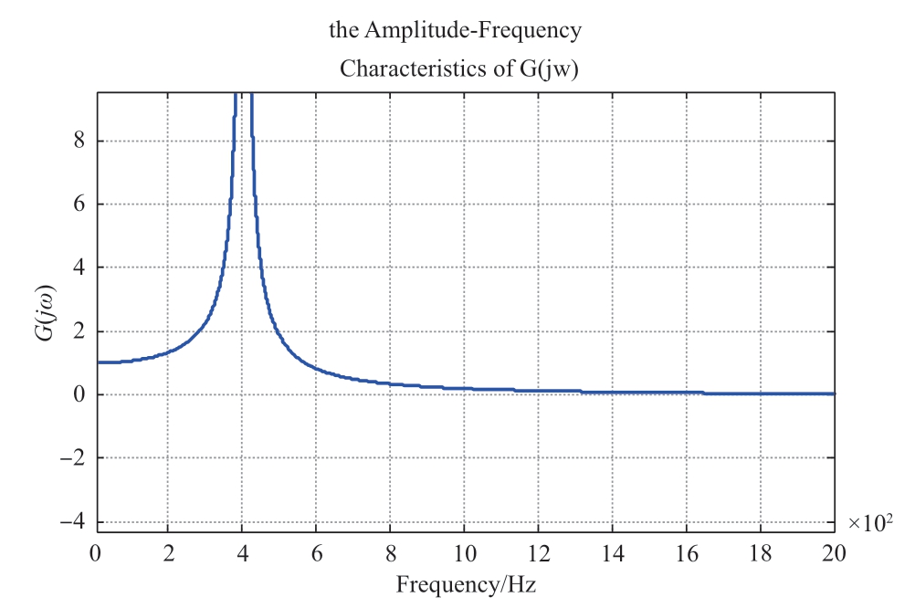
Fig.3 Amplitude-frequency characteristics of the direct power supply on the traction network boundary
1.3 Analysis of the fault processes
As faults occur at F2 (the fault inside),which implies an added voltage source at F2,an additional network diagram after the faults occur is shown in Fig.4.
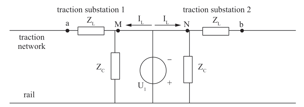
Fig.4 Additional network diagram of traction network after faults occur inside
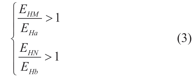
In actual engineering,each section of the line is matched with current transformers,and the letters M,N,a,and b represent the current-measuring devices.The symbol ZL represents a section of the line-equivalent impedance of the traction network,whereas the symbol ZC is the equivalent impedance of the capacitance at the traction substation exit;thus,they both form the traction network line of the boundary.If a fault occurs inside,the fault current traveling IL moves forward to checkpoints M and N directly and then undergoes attenuation from the boundary before flowing to checkpoints a and b.Consequently,the high-frequency components of the fault detected at checkpoints M and N are larger than those detected at checkpoints a and b,respectively.This is expressed as follows:
In Equation (1),the symbols EHM and EHN refer to the high-frequency components of the fault signals detected at checkpoints M and N,respectively,whereas EHa and EHb indicate the components detected at checkpoints a and b,respectively.
In terms of the formula mentioned above,the inequality targeted to both ends of the traction network line is as follows:
As faults occur in F1,the reverse faults outside,which means an added voltage source in F1.An additional network diagram after the faults occur is shown in Fig.5.
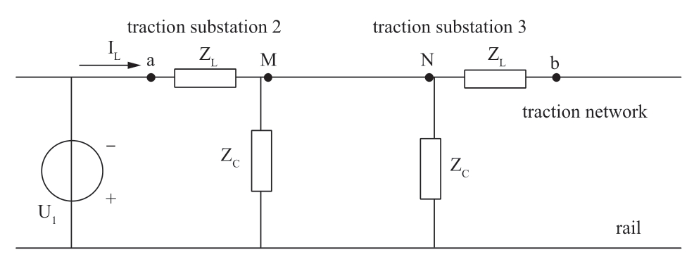
Fig.5 Additional network diagram of the traction network after reverse faults occur outside
Reverse faults occur outside before the fault current traveling wave IL directly reaches checkpoints a and M through the traction network boundary.Owing to the attenuation exerted by the border on the high-frequency component of the fault signals,the component detected at checkpoint M is smaller than that detected at checkpoint a.This is expressed as follows:
In the above formula,the following inequality is accessible in the line at the side of checkpoint M if a reverse external fault occurs:
Similarly,as faults occur in F3,the positive outside fault,the fault current traveling wave reaches checkpoint b by undergoing attenuation from the boundary and reaches checkpoint N without passing through the traction network line boundary.In this context,the following inequality is also accessible in the line on the side of checkpoint N.
In the final analysis,the detected high-frequency components of the fault current signals on both sides of boundaries M,a,N,and b vary from each other because of attenuation,regardless of the internal or external faults.However,this distinction can be applied to identify where faults occur to protect traction network lines.
2 Extraction of the fault high-frequency energy
2.1 Frequency characteristic on the traction network boundary
Gilles,a French scholar,proposed the EWT in 2013 to deal with signals and integrated the advantages of empirical mode decomposition (EMD) based on the wavelet transform.This is a new approach for analyzing time-frequency signals.The EWT is a set of bandpass filters selected according to the frequency spectrum characteristics.It can be adapted to screen the components of the amplitude and frequency modulation and classify the frequency spectrum of signals,thus forming the empirical wavelet function [20].The process for dealing with the signals is as follows:
(1) In terms of the Fourier spectrum,the signal f (x) is designed to range from 0 to [0,]π.Assuming N segmented continuous intervals,without including 0 and [0,]π,(N-1) intervals remain to be identified.The boundary of the segmented intervals is expressed as Λ n=[ω n -1,ω n],where the symbol Λn represents the corresponding frequency band of each interval,n ranges from 0 to N,and the symbols ω=0 and ωn=π are equivalent to 0 and π,respectively.Each midpoint ωn of the two adjoining maxima in the selected signals in the Fourier spectrum is designed as the center to define the transmission region with a width of Tn=2nτ,as shown in Fig.6.
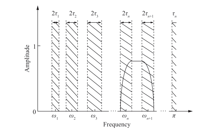
Fig.6 Results of Fourier spectrum segmentation
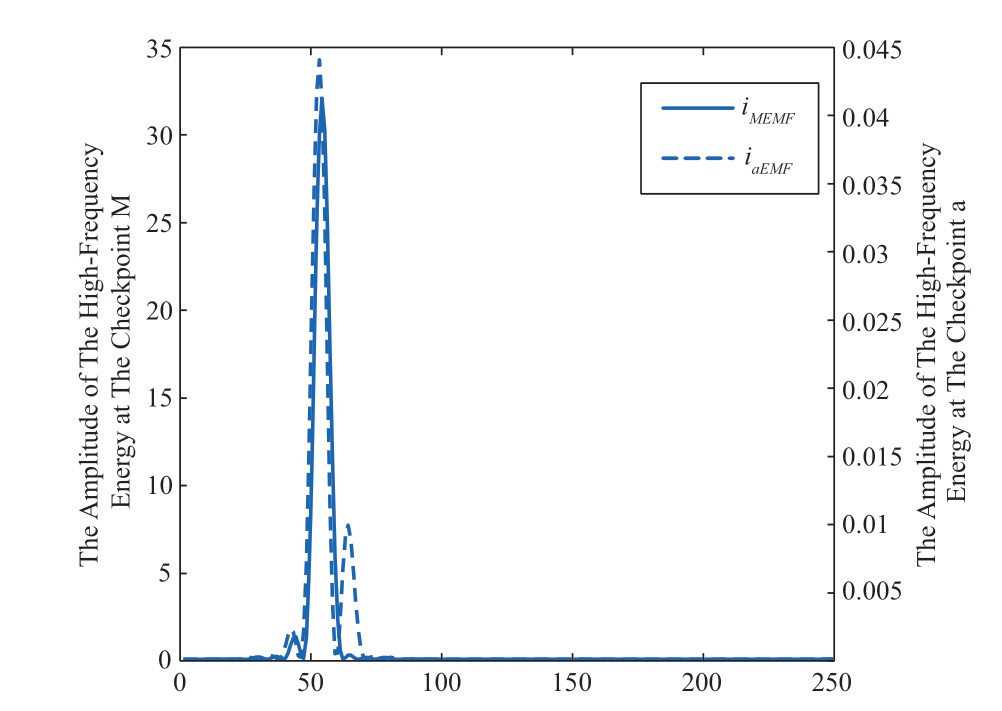
Fig.7 Transient high-frequency energy spectrum at checkpoints M and a as the midpoint was dysfunctional inside the line
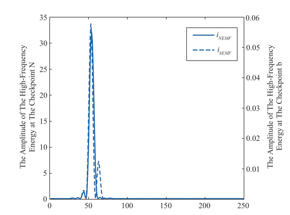
Fig.8 Transient high-frequency energy spectrum at checkpoints N and b as the midpoint was dysfunctional inside the line
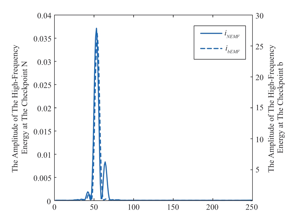
Fig.9 Transient high-frequency energy spectrum at checkpoints N and b as the midpoint was dysfunctional outside the line
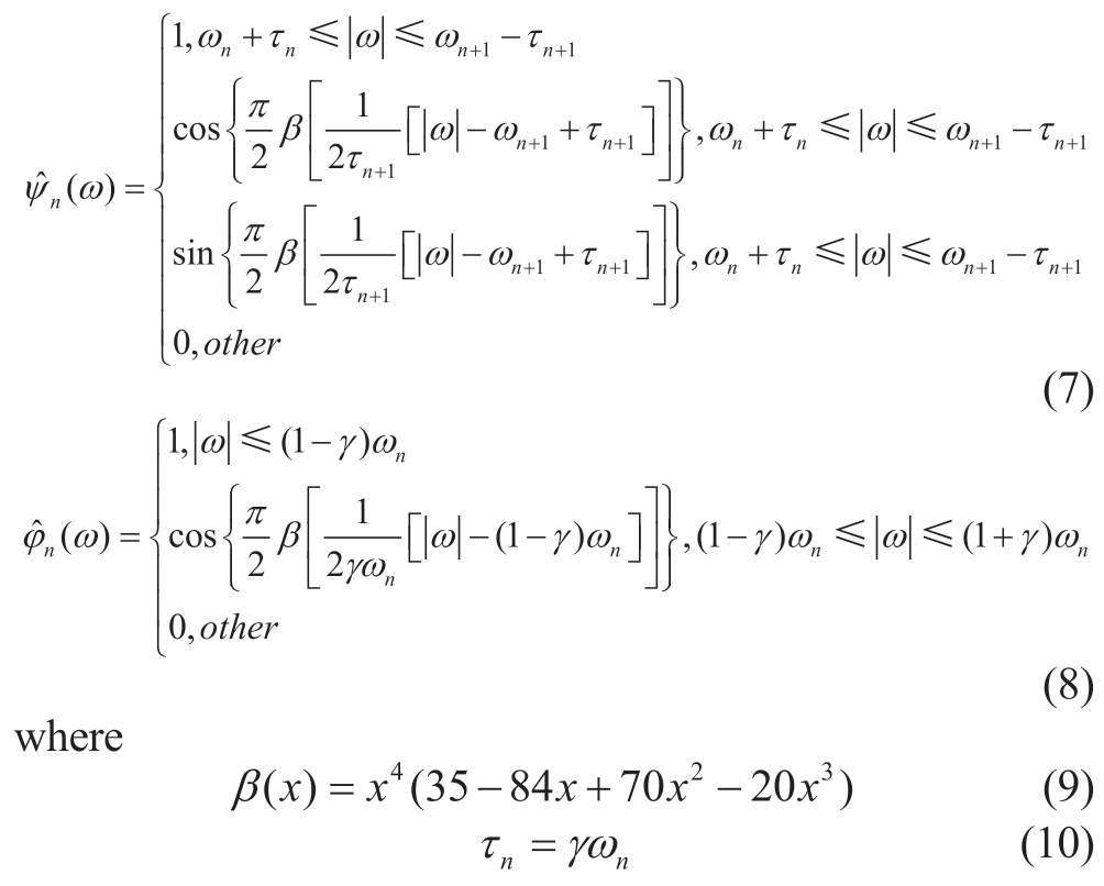
(2) Based on the method to form the Meyer wavelet function,the empirical wavelet function  (ω) and empirical scale function
  (ω) can be expressed as follows,respectively [18].

(3) As the inverse Fourier transform is conducted on the decomposed empirical mode components,the detail coefficient ωk(n,t) of the EWT is accessible through the inner product of  (ω) and the signal f(x),and the approximate coefficient ωk(0,t) is accessible through the inner product of the seal function
  (ω) and signal f(x),which is expressed as in (12),(13),respectively.
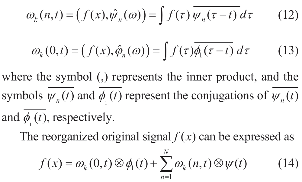
where the symbol ⊗ represents the convolution.
The mode function is

2.2 Extraction of the high-frequency energy
The results of the decomposed EMT show that the current signal i(t) is decomposed into m EMT components,namely cm(t) (m=1,2,3…,m),and a residual component cm+1(t) [17].As the traction network line boundary can weaken the high-frequency component of the fault current signals,a significant distinction in the high-frequency energy of the signal emerges from both sides of the boundary.To clarify the high-frequency energy of the fault current signals,we calculate the high-frequency band energy EH through summation after the square of the highest frequency-band coefficient was obtained.This is expressed as
In Equation (16),N represents the number of sampling points in the data time window,and cm (j) represents the empirical wavelet coefficient of the highest frequency band after the EWT decomposes.
A grounding fault simulation experiment was conducted.To achieve this,the initial fault angle was designed to be 30° with a transition resistance of 50 Ω.Two typical faults were selected,including the fault at the midpoint of the traction network line and the positive fault outside the line,taking the positive fault outside as a typical example.
The fault current signal detected at the sampling points underwent the EWT and was divided into five tiers.The transient high-frequency energy spectra at checkpoints M,a,N,and b are shown in Figures 7-9.
3 Longitudinal protection for the traction network line based on EWT
3.1 Criterion to initiate the protection
The current changing rate can demonstrate the stability of the through-type cophase traction direct-power supply system.Thus,the traction network line current is considered a standard sine wave because no fault occurs in the traction network of the system.However,if the network in the system is dysfunctional,the traction network line current must increase at a higher pace,thus distorting the waves.Consequently,the rate of current change from the traction network line current can be considered a criterion for initiating protection.This means that the criterion can function as the ratio of di/dt to fulfill the requirement to initiate.
3.2 Criterion to protect the inside and outside of the line
The analysis in Section 1.3 shows that the large parallel capacitance in the presence of a traction substation and a set of traction network lines in the through-type cophase traction direct power supply system can shape the traction network line boundary,which can dramatically attenuate the high-frequency components of the fault-current signals.Consequently,the detected high-frequency energies at the checkpoints on both sides of the boundary differ significantly.This criterion can be used to identify the faults inside and outside the line.P is the ratio of the highest frequency-band transient energy of point M to that of point a,whereas Q represents that of points N to b.
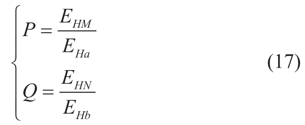
In the analysis in Section 2.3.2,because the values of P and Q are larger than 1,a fault occurs in the line.However,when the values of P and Q are less than 1,a fault occurs out of the line.In this context,the criterion shown below for initiating protection is accessible.

3.3 Procedure of the protection
The procedure for protecting the through-type cophase traction direct power supply system based on the EMT is as follows:
1.As the ratio of di/dt to di/dt fulfills the requirement to initiate,the protection scheme will function.
2.The fault current collected at checkpoints M,N,a,and b based on the EMT is considered.The high-frequency empirical wavelet coefficient is selected to calculate the energy and obtain the ratio P of the high-frequency transient energy of checkpoint M to checkpoint a,as well as the ratio Q of checkpoint N to checkpoint b.
3.When the values of P and Q are larger than 1,a fault occurs in the line and the protection scheme operates.However,when the values of P and Q are less than 1,the fault occurs outside the line,and the protection scheme does not operate.
The basic logic diagram of the protection scheme is shown in Fig.10.
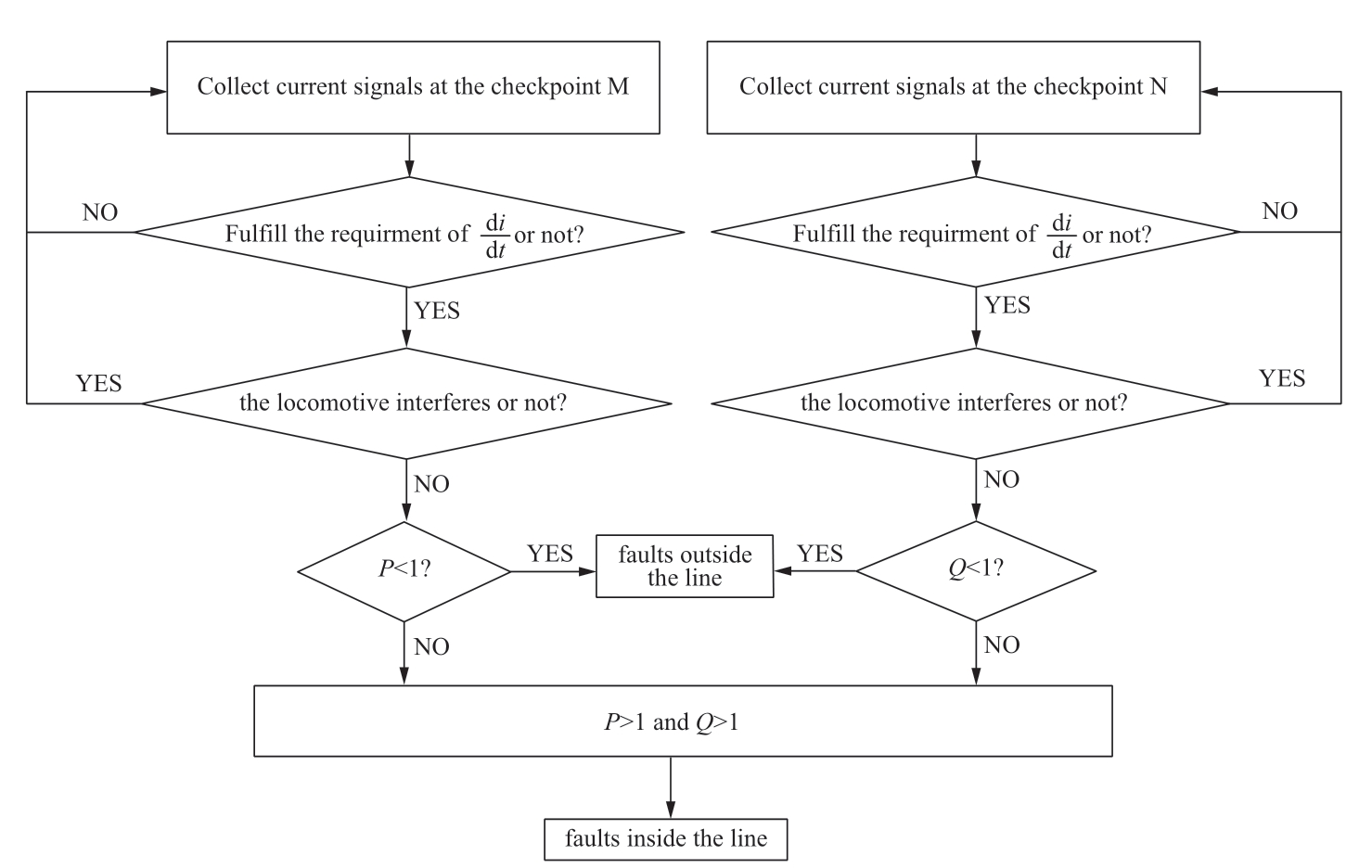
Fig.10 Logic diagram of the protection scheme
4 Simulation verification
In this study,the through-phase same-phase traction direct power supply system was modeled using a utility grid-side voltage of 220 kV,which was set as 1.0,instead of the reference system.The traction grid-side voltage was 27.5 kV,the was the standard 50 Hz,and the power capacity was 6000 MVA.The simulation application PSCAD/EMTDC was used to establish the simulation model of the through-type cophase traction direct power supply system,as shown in Fig.11.
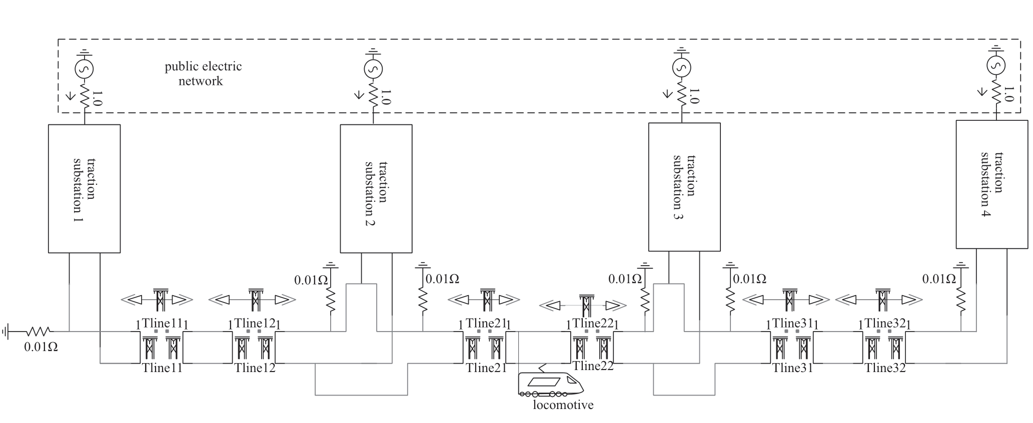
Fig.11 Simulation model of the through-type cophase traction direct power supply system
The frequency of the sampling points was designed to be 50 kHz,the traction network line was 35 km long,and the fault time was 5 ms.Thus,a simulation experiment under various fault initial angles,DTFs,and fault transition resistances was conducted to verify the mentioned methods.
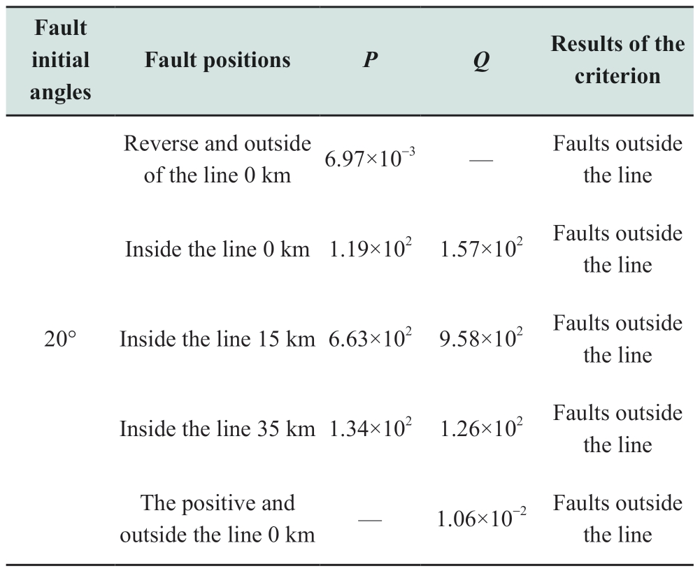
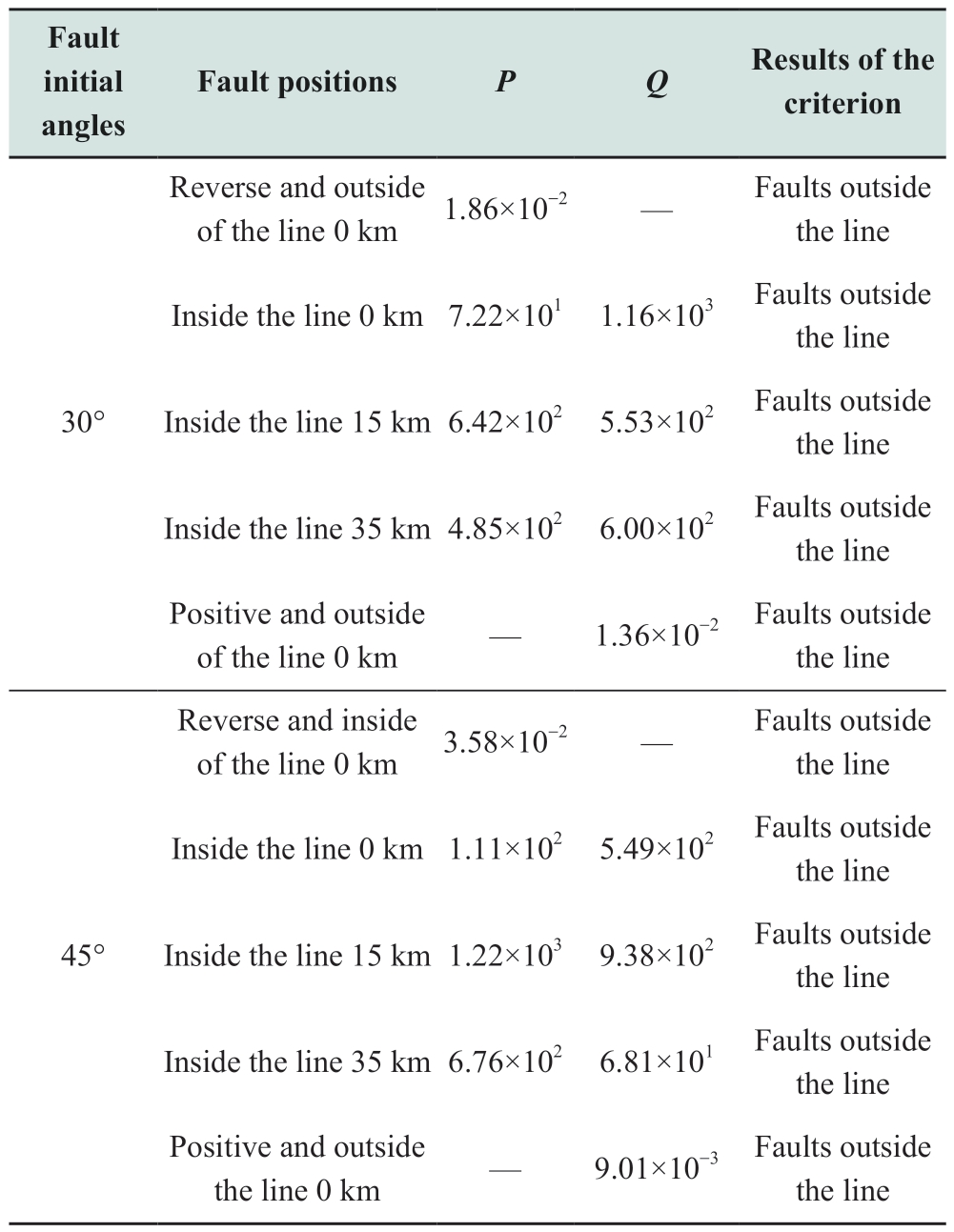
4.1 Various initial fault angles
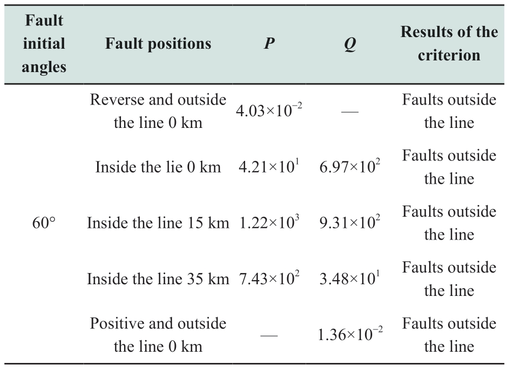
The initial fault angles were designed as 20°,30°,45°,and 60°,with the same transition resistance of 50Ω at different fault positions,particularly those that are typical.Under these circumstances,the results of the criterion for initiating protection are shown in Table 1:
Table 1 Results from the criterion to initiate the protection under different fault initial angles
continue
continue
4.2 Various distances to fault
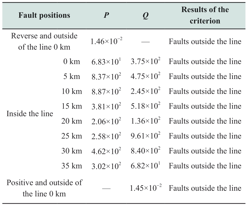
From the head to the tail end,the different distances to the fault that were designed ranged from 0,5,10,15,20,25,30,and 30 km at an interval of 5 km to record the faults on the traction line.The simulation experiment also included the same transition resistance of 0.1 Ω,with an identical initial fault angle of 20°.The results of the criterion for initiating protection are shown in Table 2.
Table 2 Results of the criterion to initiate protection under different initial fault angles
4.3 Various transition resistances
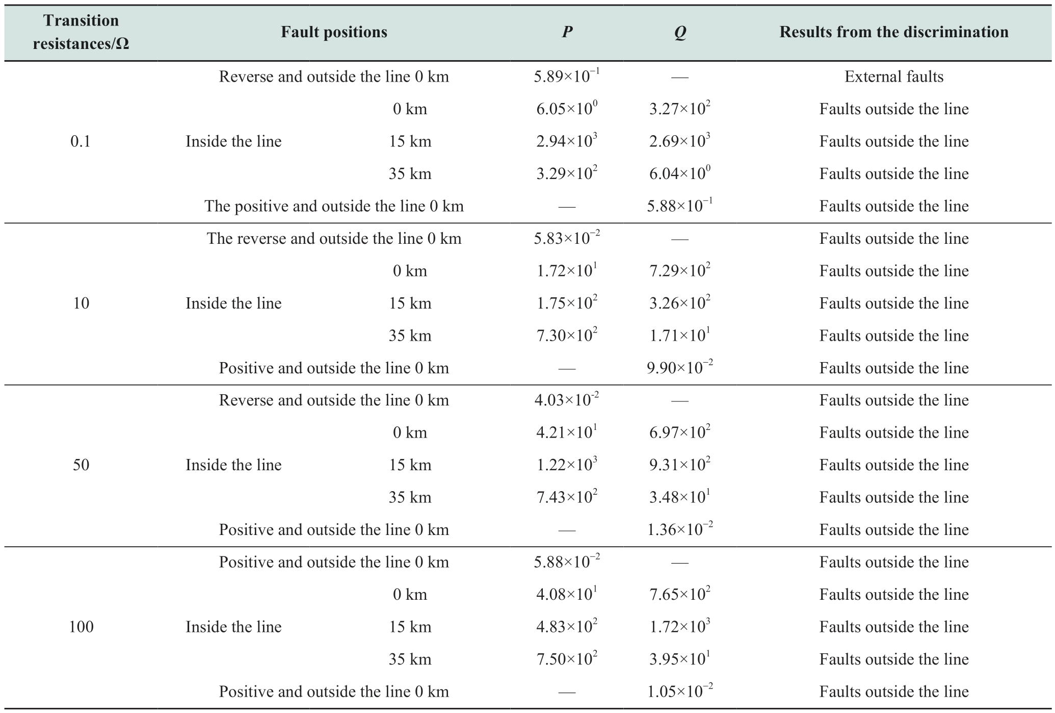
The simulation experiment was conducted under transition resistances of 0.1 Ω,50 Ω,100 Ω,and 300 Ω at various distances and identical initial fault angles of 60°.The results of these experiments are presented in Table 3.
Table 3 Results from the criterion to initiate the protection under various transition resistances
continue

Under the various initial fault angles,DTFs,and fault transition resistances in this simulation experiment,the values of the ratios P and Q of the high-frequency transient energy on both sides of the line were larger than when faults occurred in the line between points M and N.However,the values of P and Q were smaller than 1 when faults occurred beyond the line.This proved that the longitudinal protection scheme,through the attenuation that the boundary exerts on fault current signals,is effective under various fault phrase angles,fault positions,fault initial angles,DTFs,and transition resistances.
5 Conclusion
A longitudinal scheme to protect the traction network line based on the empirical wavelet was obtained based on the value of the high-frequency energy on both sides of the boundary through the attenuation exerted by the traction network line in the through-type cophase traction direct power supply system on the fault current high-frequency component.The following conclusions were drawn from the analysis of the theory and the results of the simulation experiment.
a.The parallel capacitance at the exit of the traction substation and the set of traction network lines in the through-type cophase traction direct power supply system can shape the traction network line boundary,which can significantly attenuate the high-frequency components of the fault current signals.
b.A significant difference was observed in the detected high-frequency transient energy on both sides of the traction network line boundary.The values of ratios P and Q of the high-frequency transient energy on both sides of the line are larger than one when faults occur in the line.However,the ratio of P or Q is smaller than one when faults occur beyond the line.Consequently,this ratio can be used to determine whether faults occur inside or outside a traction network line.
A large number of simulation experiments show that the longitudinal scheme to protect the through-type cophase traction direct power supply system based on EWT can discriminate faults inside or outside the line in an accurate manner and reliably protect the entire line under various fault initial angles,DTFs,and transition resistances.
Acknowledgements
This work was supported by the National Natural Science Foundation of China (51767012),Curriculum Ideological and Political Connotation Construction Project of Kunming University of Science and Technology(2021KS009),and Kunming University of Science and Technology Online Open Course (MOOC) Construction Project (202107).
Declaration of Competing Interest
The authors declare that they have no competing financial interests or personal relationships that may have influenced the work reported in this study.
References
[1] Yang H,Chen M W,Sheng W Q,et al.(2018) Modelling and operation characteristics analysis of a new continuous co-phase traction power supply system.Journal of Railway Science and Engineering,15(8): 2131-2139
[2] Guo L,Zhou L J,Chen M W,et al.(2016) Online catenary antiicing technique for electric railways employing direct feeding systems.IET Generation Transmission &Distribution,10: 1969-1975
[3] Wang H,Li Q Z,Xie S F,et al.(2020) Comprehensive compensation scheme of cophase power supply for electrified railway with dd transformer and static var generator.China Railway Science,41(4): 116-126
[4] Liu S P,Han Z Q,Gao S B (2015) Inter-tripping protection scheme for feeding sections of high-speed railway based on impedance features.Journal of Southwest Jiaotong University,50(2): 226-232
[5] Wang Y T,Zhang B H (2019) Backward travelling wavevariation-based protection for the transmission line of a hybrid HVDC system.The Journal of Engineering,2019(16): 1261-1265
[6] Luo S B,Gao H L,Wang D,et al.(2018) Non-unit transient based boundary protection for UHV transmission lines.International Journal of Electrical Power &Energy Systems,102:349-363
[7] Zou G B,Li Z,Sun C J,et al.(2018) A fast non-unit protection method based on S-transform for HVDC line.Electric Power Components and Systems,46(4): 472-482
[8] Yang Y Y,Tai N L,Liu J,et al.(2015) A pilot protection scheme for HVDC transmission lines based on boundary energy.Proceedings of the CSEE,35(22): 5757-5767
[9] Lin X N,Liu Q,Fan L X,et al.(2020) Blocking pilot protection based on ratio of superimposed energy for VSC-MTDC grid.Electric Power Automation Equipment,40(4): 2-8,16
[10] Zhou Y H,Zhang Z,Han J X,et al.(2020) A novel pilot protection based on open-close filtering and multi-resolution morphological gradient operators for HVDC transmission line.Proceedings of the CSEE,40(6): 1897-1906
[11] Zheng L M,Jia K,Bi T S,et al.(2019) Cosine similarity based pilot protection of teed transmission line connected to renewable energy power plants.Automation of Electric Power Systems,43(18): 111-119
[12] Dai Z H,Zhang C,He Y X,et al.(2020) Pilot protection based on traveling wave tuning energy for HVDC transmission lines.Power System Technology,44(7): 2710-2721
[13] Zhang Y H,Wang S L,Liu T Q,et al.(2021) A traveling-wavebased protection scheme for the bipolar voltage source converter based high voltage direct current (VSC-HVDC) transmission lines in renewable energy integration.Energy,216: 119312
[14] Cheng M W,Cui Z H,Gao H G,et al.(2017) Study of fault location method of high-speed railway using two-terminal electrical quantities.Journal of Railway Science and Engineering,14(10): 2033-2042
[15] Liu W,Tang Y W,Li F Q,et al.(2020) Two-terminal steady state fault location algorithm based on distribution parameters of railearth reflux system in DC traction power supply system.Electric Power Automation Equipment,40(11): 163-169
[16] Zhang X,Li Q,Yu L,et al.(2014) Fault location algorithm for DC traction supply based on two-ended data.Journal of the China Railway Society,36(10): 33-39
[17] Sun G Q,Liang Z,Yu N Y,et al.(2018) Short-term wind power probability density forecasting based on EWT and quantile regression forest.Electric Power Automation Equipment,38(8):158-165
[18] Gilles J (2013) Empirical wavelet transform.IEEE Transactions on Signal Processing,61(16): 3999-4010
[19] Liu W,Li S W,Wang J,et al.(2020) Identification of DC short circuit fault based on EWT energy entropy.Electric Power Automation Equipment,40(2): 149-154
[20] Kedadouche M,Liu Z H,Vu V H (2016) A new approach based on OMA-empirical wavelet transforms for bearing fault diagnosis.Measurement,90: 292-308

Scan for more details
Received:8 December 2023/Revised: 6 January 2024/Accepted:14 February 2024/Published: 25 April 2024
 Shilong Chen
chenshilong3@126.com
Lu Li
103586871@qq.com
Zeduan Zhang
1213684594@qq.com
Wang Cai
caiwang129@126.com
Qikang Zhuang
953643797@qq.com
Guihong Bi
KM_BGH@163.com
Jian Deng
1637622260@qq.com
Xiaorui Kan
kan.me@outlook.com
2096-5117/© 2024 Global Energy Interconnection Development and Cooperation Organization.Production and hosting by Elsevier B.V.on behalf of KeAi Communications Co.,Ltd.This is an open access article under the CC BY-NC-ND license (http://creativecommons.org/licenses/by-nc-nd/4.0/).
Biographies

Lu Li (1976-),Female,Ph.D.,associate professor,master’s supervisor;research interests are power market,traction power supply system,and energy economics.

Zeduan Zhang (1997-),Male,Master;research interests are power market,power economy and management,and renewable energy grid connection research.

Wang Cai (1995-),Male,Master;research interests are relay protection in power systems.

Qikang Zhuang (1996-),Male,Master;research interests are boundary protection of traction network in through-type cophase power supply systems.

Guihong Bi (1968-),Male,Ph.D,Professor,Master’s supervisor;research interests are modeling,optimization,and intelligent data analysis of new energy systems.

Jian Deng (1997-),Male,Master;research interests include new types of relay protection and its automation.

Shilong Chen (1972-),Male,Ph.D,Corresponding Author,Professor,Master’s supervisor;research interests include power system relay protection,and traction power supply systems.

Xiaorui Kan (1994-),Male,Master;research interests include power market,power economy and management,and renewable energy grid connections.
(Editor Yanbo Wang)
