0 Introduction
Owing to the advent of the global nonrenewable energy crisis,new energy sources have garnered increasing attention.Wind energy is a clean energy source,whose development has mitigated the current energy shortage problem.Modern wind power technology is becoming more mature but is restricted by improvements in wind power generation efficiency,utilization efficiency,and cost reduction.Currently,direct-drive permanent magnet synchronous generator (PMSG) has been widely used in variable-speed constant-frequency wind power generation system.
To highlight the high efficiency and reliability of synchronous generating units,they are typically designed as multipolar generators,and wind turbines and synchronous generators operate at corresponding angular velocities.Such a wind power system does not require gearboxes,thus reducing noise as well as installation and maintenance costs.However,because a wind turbine can only operate at a synchronous speed,the optimal wind energy capture efficiency cannot be maintained when the wind speed changes,thus resulting in energy wastage and efficiency deterioration.
In this study,to address the difficulty in identifying the maximum power point when the wind speed changes significantly,a fixed-step mountain climbing search method is devised.The method for identifying the maximum power reference signal is as follows: In cases where the speed controller parameters in the maximum power tracking controller cannot be self-adjusted under changes in the wind speed conditions,which affects the system performance,maximum power tracking based on a Back Propagation(BP) neural network is proposed.The controller parameter setting method improves the wind energy utilization effect in a permanent-magnet synchronous wind power generation system.
The remainder of this paper is organized as follows:Section 1 introduces the research status of the maximum power point search method and the maximum power tracking controller design method.Section 2 describes the modeling of a generator-side converter using a double-loop proportional-integral (PI) controller.Section 3 introduces the reference rotor speed generator based on fuzzy control.Section 4 introduces the neural network-based selftuning of a PI controller.Section 5 presents the simulation experiments and analyses.Finally,the conclusions are summarized in Section 6.
1 Literature review
Currently,the maximum power point search algorithm primarily includes the tip speed ratio (TSR) method [1],which requires an optimal TSR curve and is therefore difficult to transplant; the power signal feedback method [2],which requires an optimal power curve and whose parameter changes can affect the search accuracy; the hill climb search (HCS) method [3],which is proposed to overcome the shortcomings of the first two algorithms.Based on the different search steps involved,the HCS method can be classified into two types: constant and variable step lengths.
Although the method [3] improves response speed of the HCS algorithm,the search direction is inaccurate under rapid wind speed changes.Besides,It does not stop the rotor speed disturbance after searching for the MPPT but continues to perturb,thus resulting in rotor speed and output power fluctuations around the maximum power point.The long-term vibration of the drive-shaft system causes significant damage to the mechanical components of the fan.Hence,fuzzy control [4-5] and neural networks [6-8],which are products of artificial intelligence development,were applied to the maximum power point search method.
In [6],the Q-learning algorithm used featured Q-values for each state-action pair and were updated using the reward and learning rate.In [8],Q-learning was used in the proposed MPPT algorithm to learn the optimal relationship between the PMSG power and rotor speed online; subsequently,online reinforcement learning was converted into an online MPPT algorithm based on the optimal relationship.Neural network algorithms demonstrates outstanding self-learning but require long-term training,and their input/output data relationship cannot be expressed easily.
The maximum power point search method based on fuzzy logic adopts language-based control rules that are designed based on the relationship among the power difference,rotor speed difference,and rotor speed disturbance perturbation at the next moment.Unlike neural networks,this control mechanism does not require an accurate mathematical model of the controlled object.Therefore,this method is used in this study to determine the maximum power point for wind energy.
Owing to the development of wind energy conversion systems,significant achievements have been realized in terms of its control methods,including PI control,sliding mode variable structure control [9-10],robust control [11-12],and optimal control [13-14].
Sliding mode variable structure control effectively suppresses the effects of parameter changes and external disturbances on the system and improves the robustness of the control system; however,it exhibits chattering problems.Although robust control is robust to the uncertainty of the model parameters,the selection of the weight function complicates the design of the algorithm.Optimal control ensures the capture of maximum wind energy; however,its strategy is based on steady-state optimization,whereas the dynamic energy capture of the system is disregarded.As steady-state optimization involves various algorithms,the initial factors of the algorithm cannot be determined easily.PI controllers offers a simple structure,good stability,reliable operation,and easy regulation and are widely used in industry.Therefore,this control method is adopted in this study.
However,variable-speed,constant-frequency wind turbines are complex high-order nonlinear systems.The conventional PI controller can no longer satisfy highperformance control requirements; therefore,researchers have proposed self-tuning genetic algorithms [15],particle swarm optimization [16],and neural networks [17].
In [15],a genetic algorithm-based auto-tuning technique was developed to tune Proportional controllers that guarantee a delay.In [16],a particle swarm algorithm was used to optimize wind turbine PI controller parameters.In[17],a PI controller based on a radial basis function (RBF)neural network and gravitational search algorithm (GSA)was proposed.The GSA determined the best training dataset for training an RBF neural network.
In this study,a neural network-based PI controller selftuning method is proposed to address the accuracy and stability problems in wind power generation systems.The PI controller parameters are optimized via continuous self-learning and weight adjustment such that the system demonstrates favorable static and dynamic performances under rapid wind speed changes.
2 Modeling of generator side converter with double loop PI controller
A block diagram of the grid-side converter of the permanent magnet synchronous wind power generation system is shown in Fig.1.In the modeling of wind turbines,the idealized design of the generator-side model does not involve the grid-side converter; therefore,the grid-side converter is disregarded.As shown in Fig.1,the wind turbine is controlled by a double loop of external speed loop and internal current loop to maintain the optimal speed at the current wind speed,thus achieving the maximum power point search.
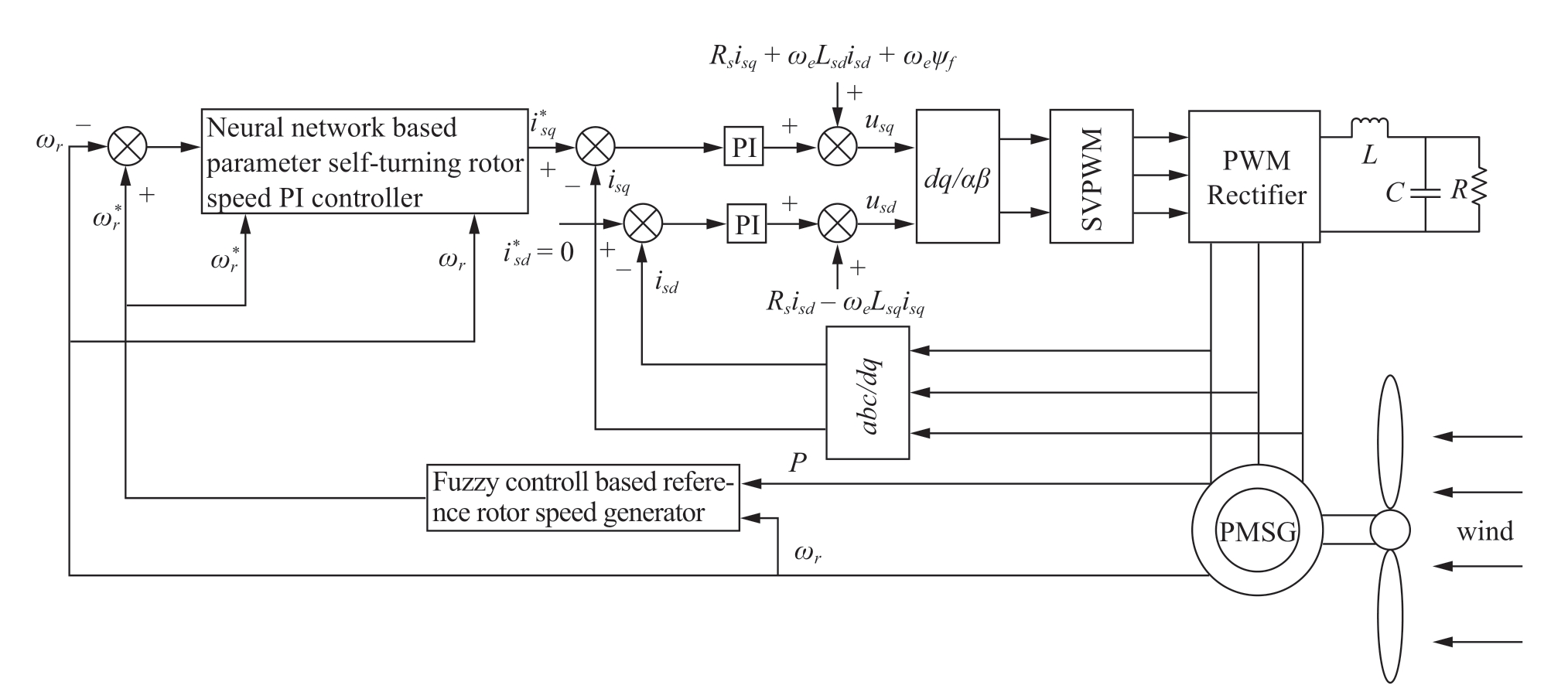
Fig.1 Diagram showing generator side converter of permanent magnet wind power generation system
2.1 Wind turbine model
The wind power output of the wind turbine is expressed as [18]
where ρ is the air density,R the fan radius,v the wind speed,λ the tip speed ratio,β the blade angle,and Cp the utilization coefficient.
As shown in Equation (1),the output value of the wind turbine is governed by the utilization coefficient.Meanwhile,Cp can be obtained as follows:

where λ is the tip speed ratio,β the blade angle,and ωr the wind turbine rotor speed.
When the blade pitch control is used,β=0.Subsequently,based on Equations (1) to (4),the wind turbine output characteristic curve is as shown in Fig.2.
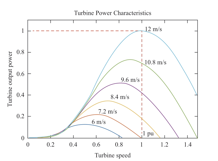
Fig.2 Output power characteristics of wind turbine
2.2 Model of generator side converter
Assuming that the PMSG is an ideal motor,the voltage equation is as follows [19]:


where Usd and Usq are the d-axis and q-axis stator terminal voltages,respectively; ψsd and ψsq are the d-axis and q-axis stator flux linkages,respectively; isd and isq are the d-axis and q-axis stator currents,respectively; ψf is the rotor flux linkage; Lsd and Lsq are the d-axis and q-axis inductances,respectively; Te is the electromagnetic torque; ωe is the electrical angular velocity; and p is the motor pole pair.
Substituting Equation (6) into Equations (5) and (7)yields

To improve the efficiency of the system and obtain large torques and high power levels for the output,a direct-drive permanent magnet synchronous motor is generally used as a surface paste,where Lsd=Lsq.Substituting this relationship into Equation (10) yields
Based on Equation (11),the electromagnetic torque is proportional to the q-axis current and independent of the d-axis current.After applying the flux linkage control strategy,all the stator currents are assumed to be expended to generate the electromagnetic torque,i.e.,the control strategy id=0 is adopted.When the speed command is known,the d-q axis current command is:

Subsequently,the control equation of the permanent magnet synchronous motor in steady state can be written as follows:

In order to allow the actual current to follow a given current,the feedback control is introduced.A PI controller is adopted in this study,and the final form of the system control equation is

where Kp and Ki are the proportional and integral coefficients of the current loop,respectively; εd= -isd is the d-axis input feedback error; and εq=
 -isq is the q-axis input feedback error.
The electromagnetic power of the generator is expressed as
Therefore,the generator output power is
where Pcu is the copper motor consumption.
Equations (11) and (15) indicate that the electromagnetic torque of the motor can be controlled by changing the q-axis current component; thus,the electromagnetic power of the motor can be controlled.
3 Fuzzy control based reference rotor speed generator
The conventional hill climbing method adopts a fixed rotor speed disturbance.When the wind speed changes significantly,the unit fluctuates,which renders it difficult to identify the best rotor speed timely.To address the step length in the conventional hill climbing method to capture the maximum wind energy,we combined fuzzy control with conventional hill climbing and used fuzzy rules to solve the fixed-step size problem in the conventional hill climbing to improve the accuracy of maximum power point search.The structure of maximum power point search based on fuzzy control is shown in Fig.3.
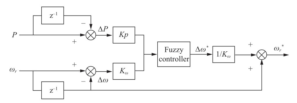
Fig.3 Structure of the fuzzy control based reference rotor speed generator
The power difference ΔP and rotor speed difference Δωr of the generator per unit time are regarded as the input variables of the fuzzy controller.The following new rotor speed increment Δω* is used as the output variable of the fuzzy controller.z-1 represents the time delay of the unit cycle.Kp and Kω are the quantification factors for the power and rotor speed differences,respectively.
3.1 Determination of fuzzy rules
A diagram of the hill climbing search process is shown in Fig.4.The graph shows that the velocity increases in the following manner:
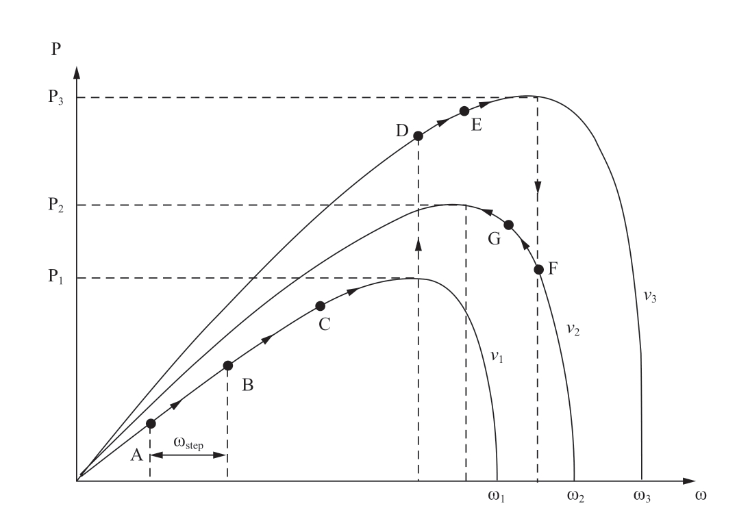
Fig.4 Diagram of the hill climbing search process
1) When the rotor speed varies less at a fixed wind speed,the power variation is significant,which implies that the operating point of the rotor speed is distant from the optimal speed point; therefore,the rotor speed increment output from the fuzzy controller should be large.
2) When the rotor speed varies less at a fixed wind speed,the power variation is relatively insignificant,which implies that the rotor speed operating point is near the optimal speed point; therefore,the rotor speed increment output from the fuzzy controller should be smaller.
3) When the rotor speed varies less at a fixed wind speed,the power variation is moderate,which implies that the rotor speed working point is moderately far from the optimal speed point; therefore,the rotor speed increment output from the fuzzy controller should be moderate.
4) When the rotor speed varies widely at a fixed wind speed,the slight power change implies that the rotor speed working point is to the right of and distant from the optimal speed point; therefore,the rotor speed increment output from the fuzzy controller should be larger.
5) When the rotor speed varies widely at a fixed wind speed,a significant change in power implies that the operating point of the rotor speed is close to the left of the optimal speed point.Therefore,the rotor speed increment output of the fuzzy controller must be small.
6) When the rotor speed varies widely at a fixed wind speed,a moderate power variation implies that the operating point of the rotor speed is moderately far from the optimal speed point; therefore,the rotor speed increment output from the fuzzy controller should be moderate.
After the rotor speed is determined,the direction of the rotor speed increment can be determined based on the following rules:
1) When the power and rotor speed differences are less than 0,the rotor speed increment should be greater than 0 to reach the maximum power point.
2) When the power difference is greater than 0 and the rotor speed difference is less than 0,the rotor speed increment should be less than 0.
3) When the power difference is less than 0 and the rotor speed difference is greater than 0,the rotor speed increment should be less than 0.
4) When the power difference and rotor speed difference are greater than 0,the rotor speed increment should be greater than 0.
5) When the power difference is 0,the operating point is at the maximum power point and the rotor speed increment is 0.
6) When the rotor speed difference is zero,the power difference is greater than zero,thus indicating an increase in the wind speed.At this time,the operating point is to the left of the maximum power point; therefore,the rotor speed increment should be greater than 0.
7) When the rotor speed difference is zero,the power difference is less than zero,thus indicating that the wind speed decreases.At this time,the operating point is to the right of the maximum power point; therefore,the rotor speed should be greater than 0.
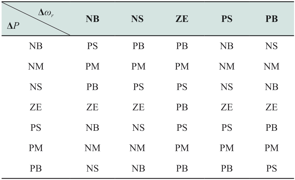
Based on the analysis above,ΔP and Δω* can be established as fuzzy linguistic variables NB,NM,NS,ZE,PS,PM,and PB; and Δωr can be established as fuzzy linguistic variables NB,NS,ZE,PS,and PB,where NB,NM,NS,ZE,PS,PM,and PB represent negative large,negative medium,negative small,zero,positive small,positive medium,and positive large,respectively.The fuzzy rules are presented in Table 1.
Table 1 Fuzzy control rule table
3.2 Fuzzification of variable and selection of membership functions
After constructing the fuzzy rule,which is the core of the fuzzy controller,the digital inputs must be encoded using an assembly of fuzzy sets.Subsequently,the fuzzy control rules can be used to perform fuzzy reasoning.The change interval of ΔP and Δωr is known as the physical domain,and after scaling,the corresponding fuzzy range is known as the fuzzy domain.
For wind speed measurements on wind farms,an anemometer is typically used to obtain one wind speed point for 1 s,and the wind speed changes by no more than 2 m/s.Therefore,the wind speed shown in Fig.5 was used as the input signal,and the initial rotor speed was set to the optimum value corresponding to a wind speed of 6 m/s.The rotor-speed difference curve is presented in Fig.6.

Fig.5 Wind speed
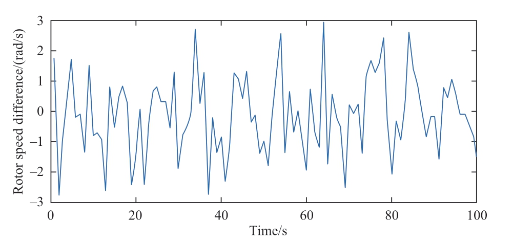
Fig.6 Rotor speed difference
As shown in Fig.6,the maximum value of the rotor speed difference is 3; therefore,the physical domain of the rotor speed difference is [-3,3].Similarly,the physical domain of the power difference is [-300,300].Here,we define the fuzzy domains of power difference and rotor speed difference as YP and Yω,respectively.Based on YP=Yω=[-3,3],the quantification factors from the physical domain to the fuzzy domain are as follows:
The scope of the fuzzy domain Y=[-y0,y0] is provided,and the actual value may not ideally exceed the specified range owing to external interference in the actual operation.Therefore,a certain processing margin must be maintained.
If the input variable in the physical domain is xi at a certain moment,then before transforming it into the fuzzy domain by yi=kixi and inputting it into the fuzzy controller,the quantized values in the fuzzy domain are processed as follows:

After this processing,whether the input variable is within of outside the specified range,it can still be guaranteed to be obfuscated,i.e.,yi ∈ Y=[-y0,y0].
The common and convenient calculation triangular membership function is adopted.For the rotor speed difference,the membership function is shown in Fig.7.
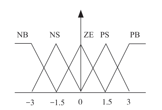
Fig.7 Rotor speed difference membership function
3.3 Fuzzy reasoning and defuzzification
After determining the fuzzy rules and fuzzy membership functions of the power difference,rotor speed difference,and rotor speed increment,fuzzy inference must be performed on the fuzzy variables.Subsequently,the reasoning result must be defuzzified to obtain the corresponding rotor speed increment in the fuzzy domain.
3.3.1 Fuzzy reasoning
The Mamdani fuzzy inference method was used.The fuzzy implication relation R(yP,yω) was obtained from the Cartesian product of the fuzzy sets UP(yP) and Uω(yω) as follows:
where UP(yP) is the value representing the current power difference in the fuzzy domain and corresponds to the membership set column vector of the fuzzy domain center,and there are 7 elements in total.Uω(yω) is the value representing the current rotor speed difference in the fuzzy domain and corresponds to the membership set column vector of the fuzzy domain center,where five elements are involved.R(yP,yω) implies that each element in the two vectors passes through “implicit operations,” i.e.,Cartesian product operations.A total of 35 elements correspond to 35 fuzzy control statements in the fuzzy control rule table.
After the operation,the following association matrix can be constructed:

3.3.2 Defuzzification
The fuzzy quantity was obtained after fuzzy reasoning.After defuzzification,a definite value was required to control the actual system.The center of gravity method is adopted to defuzzify.The center of gravity formula is as follows:

where Δω* is the actual specified value of the rotor speed increment,Ai the linguistic variable quantized value corresponding to the fuzzy subset in the i-th control statement conclusion in the fuzzy setting rule table,ui the element value of the corresponding position of the i-th fuzzy control statement in the abovementioned fuzzy relation matrix,and n the number of elements.
4 Neural network-based self-tuning PI controller
Conventional PI controllers cannot self-tune online parameters,and ensuring the good dynamic quality of the system under different operating conditions is difficult.
4.1 Neural network self- tuning PI controller structure
The controller comprises two components: One is the conventional PI controller,which does not possess the static tracking capability of the rotor speed component,and involves two controller parameters (Kp and Ki),which are rectified online by the neural network.The other is the structure of the BP neural network.Based on the operational state of the controlled object,specific weight adjustment rules are used to continuously modify and optimize the parameters of the controller such that the neural network output neurons correspond to the two optimal control parameters of the PI controller.A block diagram of the PI controller based on a neural network is shown in Fig.8.For the conventional incremental digital PI controller,the input is set as e(k),the output is u(k),and the formula for the PI controller is

Fig.8 Diagram showing neural network-based parameter self-tuning module and rotor speed PI controller

The PI controller can be expressed as the following nonlinear function:
where u(k-1) is the output of the PI controller at the last moment; e(k-1) is the input of the PI controller at the last moment; x(k) is the reference input; y(k) is the control object.
A rotor-speed control system is a complex multivariable system.Using a BP neural network to approximate a controlled object can yield good results.Depending on the complexity of the object,a structure can be constructed based on a neural network algorithm.The input layer comprises three neuron nodes,i.e.,the specified spee ωr*,the actual speed output ωr,and the difference Δωr between the two.The output layer comprises two neuron nodes: the proportional coefficient Kp and the integral coefficient Ki of the PI regulator.The hidden layer was set in five nodes.Through the self-learning and continuous training of the neural network structure,the optimal control parameters of the PI regulator can be achieved online.
4.2 Neural network adaptive PI control algorithm
The BP neural network algorithm comprises two components: forward learning of the signal and backward transmission of errors.During signal forward learning,the input of each neuron node is a weighted sum of the nodes in the previous layer,which is output to the next layer via the excitation function.In the backward error transmission process,if the system output deviates from the desired output,then the gradient descent algorithm is used to correct the weights of each layer of the network structure based on the minimum deviation function.
x1=ωr,x2=ωr*,and x3=Δωr are the inputs of the neural network; y1=Kp and y2=Ki are the outputs of the neural network; ωji(i=1 and 2,and 3; j=1,2,3,4,and 5) is the weight of the input layer to the hidden layer; and βkj (k=1 and 2; j=1,2,3,4,and 5) is the weight of the hidden layer to the output layer.Subsequently,based on the neural network model,the input of network hidden layer can be obtained as follows:
Because the PI controller parameters cannot be negative,the non-negative sigmoid function is the excitation function,and the hidden layer output can be expressed as
Similarly,the input of the network output layer can be expressed as
Using the non-negative sigmoid function as the output layer excitation function,the output layer can be expressed as
where f(x) is the sigmoid activation function,the function prototype expression is:
The parameter optimization of the BP neural network algorithm uses a gradient descent algorithm to obtain the optimal control law of the index function to optimize a certain index function.In this system,the target optimization function is selected as the 2-norm of the error between the rotor speed input x1 and rotor speed output x2 as follows:
To minimize this error,a gradient descent algorithm can be used to correct the weights between layers.To solve the problem in which the BP algorithm cannot guarantee the global minimization of the required hyperplane,we implemented a BP neural network with a momentum term.The additional momentum method allows to ignore small changes in the network characteristics,allowing the network to slip over local minimum point,the use of additional momentum method can get the hidden layer to the output layer weight correction:
where η is the learning rate and α is the inertia coefficient.Based on the chain derivation law of the composite function,the following expression can be obtained:

Because ∂x1(k)/∂Δu(k) is unknown,the symbolic function sgn(∂x1(k)/∂Δu(k)) replaces ∂x1(k)/∂Δu(k),and the resulting calculation of imprecise effects can be adjusted by adjusting the learning rate η.Based on Equation (22),we obtain

Using the formula above,we obtain the hidden layer-tooutput layer weight-correction algorithm as follow:
Similarly,the input layer for the hidden-layer connection weight correction algorithm is obtained as follows:

4.3 Neural network PI controller process
By using the self-correcting algorithm of neural network weights,the online optimum tuning of the PI controller parameters can be achieved to change the output of the input monitoring commands and improve the monitoring accuracy.The algorithm of the speed-loop system based on the neural network self-tuning PI control is as follows:
1) Determine the topological structure of the BP neural network,initialize the weights,and select the appropriate learning rate η and inertia coefficient α.
2) Sample and obtain the output rotor speed signal and specified rotor speed signal,and calculate the current rotor speed difference value Δω.
3) Input the specified speed signal,speed output signal,and current speed difference signal into the BP neural network; based on process output from the forward information of the neural network,calculate the output (Kp,Ki) of the neural network.
4) Based on the mathematical expression of an incremental digital PI regulator,obtain the deviation of the controller output Δu(k).
5) Use the gradient descent algorithm to calculate the network weights to adjust the weights of the network structure and realize an adaptive adjustment of the PI control parameters.
6) Let k=k + 1,return to step 2).
To address the problems of multivariable,nonlinear,and time-varying wind power generation systems,a selftuning PI controller based on neural networks that utilizes neural networks for the infinite approximation of nonlinear complex systems was designed.By optimizing the control parameters of the PI controller through self-learning and weight adjustment,the system exhibited good dynamic and static performances,high tracking accuracy,and strong parameter robustness under different conditions.
5 Simulation and analysis
Simulations were conducted using Simulink to validate the proposed method.Table 2 lists the PMSG parameters used in the simulations.
Table 2 Parameters of the PMSG

The aim of the maximum power point search was to maintain the maximum power output of the wind power system under variable wind speeds.To reflect random,intermittent,and abrupt changes in the wind speed,the wind speed model shown in Fig.9 was used as the input for the entire wind power system in this study.

Fig.9 Results of rotor speed
Figs.10 and 11 show the power comparison curves under the fuzzy control and hill climbing approaches,as well as the difference in area distribution between the two.As shown in Fig.10,the rotor speed under hill climbing does not track to the optimum rotor speed in most cases.As shown in Fig.11,the power of the fuzzy control exceeded that of the hill climbing control in most cases,and the difference was significant,thus indicating that the fuzzy control obtained more wind energy than hill climbing.

Fig.10 Results of active power variation
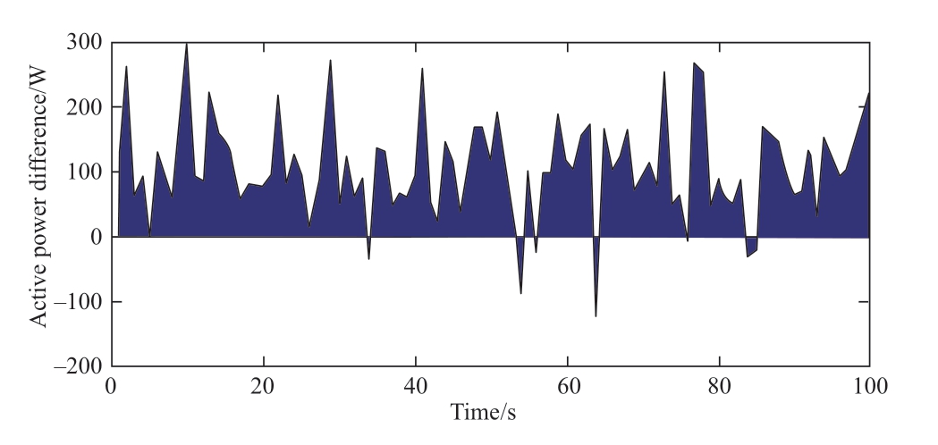
Fig.11 Power difference between the proposed generator and the hill climbing
Fig.12 shows the curve of the wind energy utilization coefficient under fuzzy control and hill climbing.As shown,most of the wind energy utilization coefficients based on fuzzy control exceeded 0.45 under variable wind speeds.However,the wind energy utilization coefficient under hill climbing was varied significantly,and it was approximately 0.3 when the wind speed changed considerably.This indicates that the hill climbing method cannot effectively monitor the optimum rotor speed under rapid changes in the wind speed,nor can it effectively suppress rotor speed fluctuations caused by wind speed noise,thus resulting in low-accuracy point monitoring.
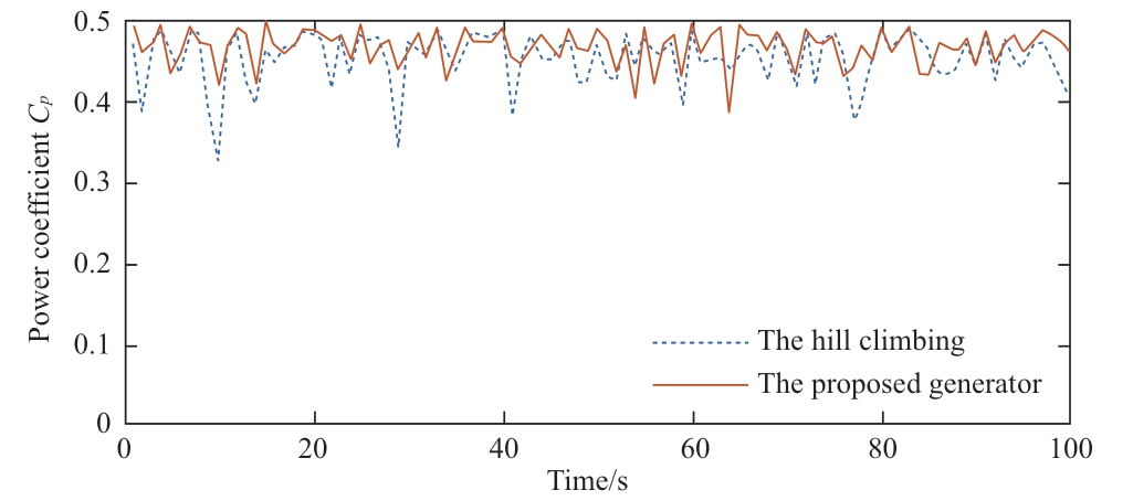
Fig.12 Wind energy utilization coefficient
In summary,the maximum power point tracking method based on fuzzy control satisfies the requirements for maximum wind-energy capture and is feasible.
During maximum power tracking,the conventional PI controller used by the rotor speed controller cannot selftune the parameters,and the good dynamic quality of the system under different wind speed conditions is challenging.In this study,a neural network-based self-correcting PI controller was designed to provide good dynamic and static performances despite external wind speed disturbances.
Both the switching and sampling frequencies were set to 5 kHz,and the system simulation time was 90 s.The neural network learning rate η was 0.3,the inertia coefficient α was 0.05,and the initial value of the weighting coefficient was a random number in the interval [-0.5,0.5].The maximum number of iterations was 100,and the error accuracy was set to 0.001.
Because the step signal significantly affects the system and can be analyzed and calculated easily,considering the wind speed shown in Fig.13 as the input of the entire machine-side model,the designed neural network selftuning PI controller was used as the rotor speed controller.The control effect of the neural-network PI controller was verified based on the electromagnetic torque,active power,and power coefficient of the unit,whereas the dynamic and static performances were verified based on two aspects: the overshoot and adjustment time.Therefore,we believe that the proposed method presents a relatively low computational burden and is suitable for online operations.
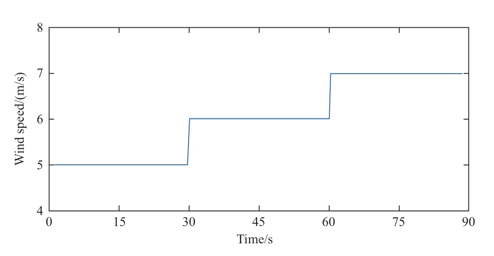
Fig.13 Simulated wind speed as step signal

Fig.14 Variation in Kp under step wind speed

Fig.15 Variation in Ki under step wind speed
The three wind-speed curves are shown in Fig.13.At 0-30 s,the wind speed was 5 m/s; 30-60 s,6 m/s; and 60-90 s,7 m/s.Based on the error index function,a gradient descent algorithm was used to calculate the network weightadjustment algorithm.The weight of the network structure was self-adjusted until the error reached a certain range.Subsequently,a new set of controller parameters was obtained.The curves of Kp and Ki varying with the wind speed are shown in Figs.14 and 15,respectively.
As show in the figures,when the wind speed changed,the values of Kp and Ki changed,although the value of Kp did not change significantly,thus indicating that the response speed of the system was not significantly affected by the increase in the wind speed.The change in Ki was significant,and it decreased continuously as the wind speed increased.
Figs.16-19 show the comparison curves of the rotor speed difference,electromagnetic torque,active power,and power coefficient under the neural network PI controller and conventional PI controller,respectively.As shown,when the wind speed changed,because the neural network PI controller can self-tune the controller parameters,the rotor speed difference,electromagnetic torque,active power,and power coefficient stabilized within a short duration.
Based on Fig.16 as an example,the wind speed changed at 30 s.Compared with the PI controller,the neural network PI controller required a shorter adjustment time by approximately 70%.Because the parameters of the neural network PI controller were self-tuned at this time,the overshoot was slightly greater than that of the PI controller,although the system performance requirements were satisfied,and the dynamic and static performance of the neural network PI controller was better than that of the conventional PI controller under the external wind speed disturbance,thus ensuring the accurate monitoring of the maximum power point.
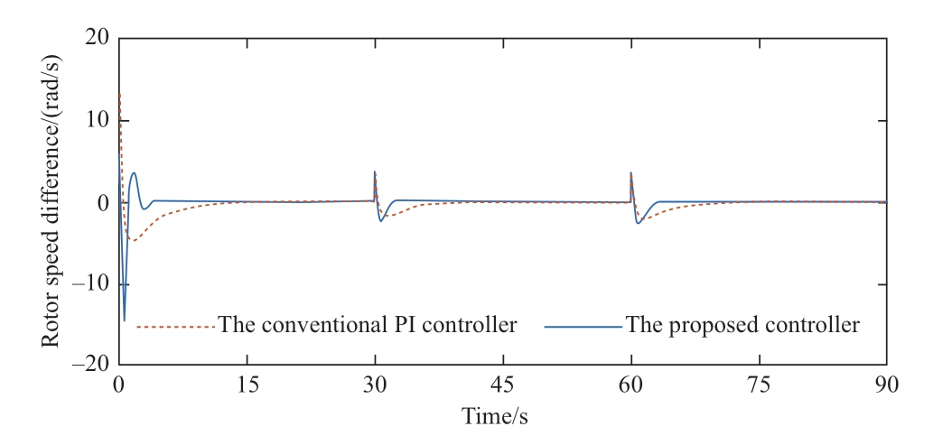
Fig.16 Results of rotor speed difference under step wind speed

Fig.17 Results of electromagnetic torque under step signal
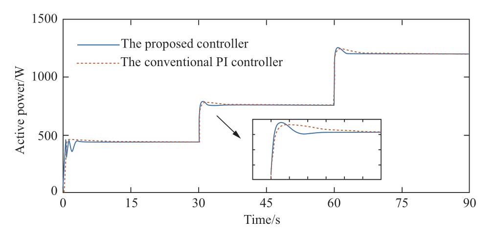
Fig.18 Results of active power under step wind speed

Fig.19 Results of power coefficient under step wind speed

Fig.20 The curve of Kp

Fig.21 The curve of Ki
Based on the actual wind speed shown in Fig.5 as the input to the system,Figs.20 and 21 show the curves of Kp and Ki changing with the wind speed,respectively.As the wind speed changed,Kp increased gradually,whereas Ki decreased gradually,and the change in amplitude was not significant as compared with the initial value.Meanwhile,an analysis of the difference in the rotor speeds shown in Fig.22 shows that the speed difference under the neural network PI controller fluctuated within a small range and the control effect was favorable.
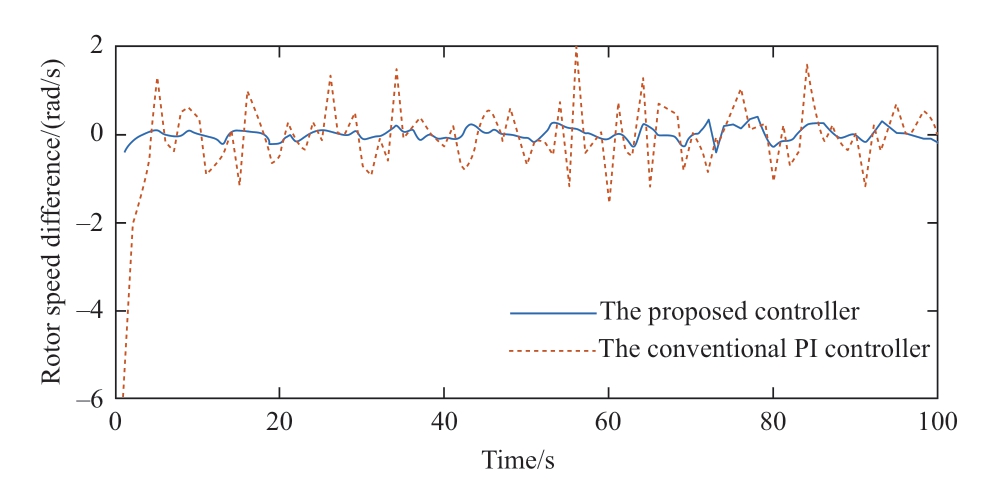
Fig.22 The curve of rotor speed difference
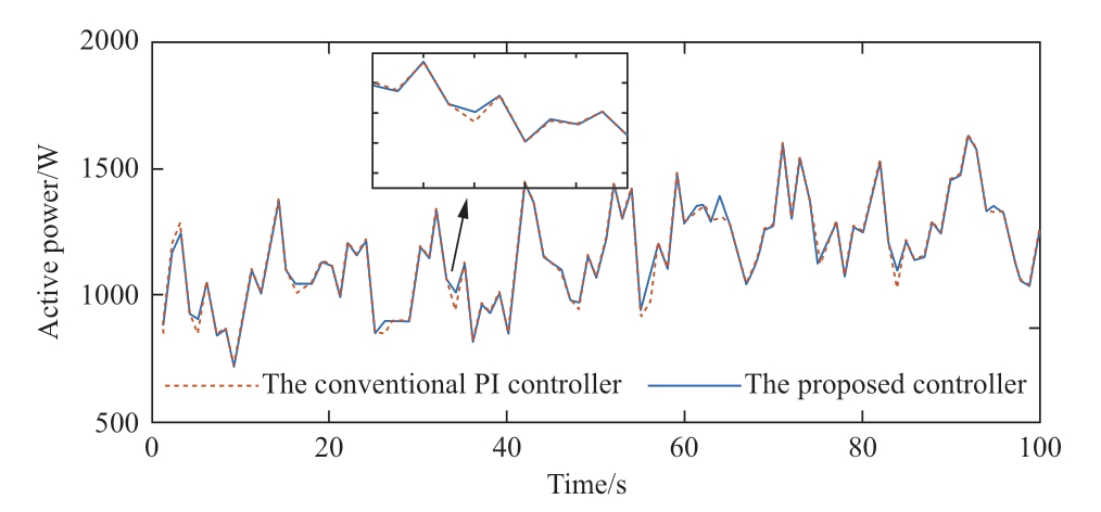
Fig.23 Active power under the conventional PI controller and the neural network PI controller
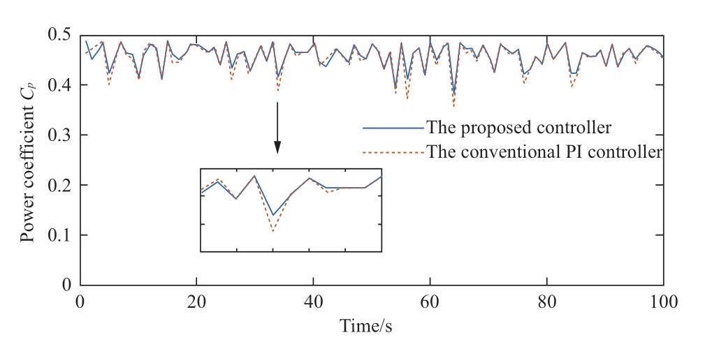
Fig.24 Power coefficient under the conventional PI controller and the neural network PI controller
Figs.23 and 24 show the comparison curves of the active power and wind energy utilization coefficients under the neural network and conventional PI controllers,respectively.As shown,the active power and wind energy utilization coefficients under the neural network PI controller exceeded those under the conventional PI controller when the wind speed changed significantly.
In summary,the control performance of the neural network PI controller was better than that of the conventional PI controller under external wind speed disturbance,and its control advantage was more evident,particularly when the wind speed changed considerably.
6 Conclusion
In this study,a maximum power reference signal search method was designed based on fuzzy control to improve hill climbing search.A parameter-setting method for a maximum power tracking controller based on a BP neural network was proposed to address the issue of speed controller parameters in the maximum power monitoring controller,i.e.,the inability to self-adjust to changes in the wind speed,which affects system performance.By considering external wind speed disturbances,we proposed a neural network PI controller with better control performance than classical PI controllers,which effectively improved the utilization efficiency of wind energy in permanent magnet synchronous wind power generation systems.
Acknowledgements
This study was supported partially by the National Natural Science Foundation of China under Grant 61503348,the Hubei Provincial Natural Science Foundation of China under Grant 2015CFA010 and the 111 project under Grant B17040.
Declaration of Competing Interests
The authors have no conflicts of interest to declare.
References
[1] Jeong H G,Seung R H,Lee K B (2012) An improved maximum power point tracking method for wind power systems.Energies,5(5): 1339-1354
[2] Chang T P,Liu F J,Ko H H,et al.(2014) Comparative analysis on power curve models of wind turbine generator inestimating capacity factor.Energy,73(7): 88-95
[3] Kesraoui M,Korichi N,Belkadi A (2011) Maximum power point tracker of wind energy conversion system.Renewable Energy,36(10): 2655-2662
[4] Pan C T,Juan Y L (2010) A novel sensorless mppt controller for a high-efficiency microscale wind power generation system.IEEE Transactions on Energy Conversion,25 (1): 207-216
[5] Bezza M,Moussaoui B E L,Fakkar A (2012) Sensorless mppt fuzzy controller for dfig wind turbine.Energy Procedia,18(4):339-348
[6] Kushwaha A,Gopal M,Singh B (2020) Q-learning based maximum power extraction for wind energy conversion system with variable wind speed.IEEE Trans.Energy Convers,35(3):1160-1170
[7] Alzayed M,Chaoui H,Elhaji E,et al.(2023) Universal Maximum Power Extraction Controller for Wind Energy Conversion Systems Using Deep Belief Neural Network.IEEE Transactions on Sustainable Energy,14(1): 630-641
[8] Wei C,Zhang Z,Qiao W,et al.(2016) An adaptive networkbased reinforcement learning method for mppt control of pmsg wind energy conversion systems.IEEE Transactions on Power Electronics,31(11): 7837-7848
[9] Torchani B,Sellami A,Garcia G (2016) Variable speed wind turbine control by discrete-time sliding mode approach.Isa Trans,62: 81-86
[10] Haq I U,Khan Q,Khan I,et al.(2020) Maximum power extraction strategy for variable speed wind turbine ystem via neuro-adaptive generalized global sliding mode controller.EEE Access,8: 128536-128547
[11] Buduma P,K Vulisi N,Panda G (2021) Robust control and Kalman MPPT or grid-assimilated wind energy conversion system.IEEE Trans Ind Ppl,57(2): 1274-1284
[12] Berkoune K,B Sedrine E,Vido L,et al.(2017) Robust control of hybrid excitation synchronous generator for wind applications.Mathematics and Computers in Simulation,131: 55-75
[13] Mesemanolis A,Mademlis C,Kioskeridis I (2013) Optimal efficiency control strategy in wind energy conversion system with induction generator.IEEE Journal of Emerging and Selected Topics in Power Electronics,1(4): 238-246
[14] Zamanifar M,Fani B,Golshan M E H,et al.(2014) Dynamic modeling and optimal control of dfig wind energy systems using dft and nsga-ii.Electric Power Systems Research,108 (3): 50-58
[15] Jimnez T,Merayo N,Andrs A,et al.(2015) An auto-tuning pid control system based on genetic algorithms to provide delay guarantees in passive optical networks.Expert Systems with Applications,42(23): 9211-9220
[16] Kim Y S,Chung I Y,Moon S I (2015) Tuning of the pi controller parameters of a pmsg wind turbine to improve control performance under various wind speeds.Energies,8(2): 1406-1425
[17] Assareh E,Biglari M (2015) A novel approach to capture the maximum power from variable speed wind turbines using pi controller,rbf neural network and gsa evolutionary algorithm.Renewable and Sustainable Energy Reviews,51(5-6): 1023-1037
[18] Morimoto S,Nakayama H,Sanada M,et al.(2005) Sensorless output maximization control for variable-speed wind generation system using ipmsg.IEEE Transactions on Industry Applications,41(1): 60-67
[19] Tan K,Islam S (2004) Optimum control strategies in energy conversion of pmsg wind turbine system without mechanical sensors.IEEE Transactions on Energy Conversion,19(2): 392-399
Received: 8 May 2023/ Accepted: 28 July 2023/ Published: 25 October 2023
✉Min Ding
dingmin@cug.edu.cn
Zili Tao
Taozl0947@163.com
Bo Hu
bo1-hu@geidco.org
Meng Ye
1923899303@qq.com
Yingxiong Ou
946256109@qq.com
Ryuichi Yokoyama
yokoyama-ryuichi@waseda.jp
2096-5117/© 2023 Global Energy Interconnection Development and Cooperation Organization.Production and hosting by Elsevier B.V.on behalf of KeAi Communications Co.,Ltd.This is an open access article under the CC BY-NC-ND license (http: //creativecommons.org/licenses/by-nc-nd/4.0/).
Biography

Min Ding received her B.S.degree in engineering from Central South University,Changsha,China,in 2009,and her Ph.D.degree in engineering from the Waseda University,Tokyo,Japan,in 2014.She is a faculty member of China University of Geosciences,Wuhan,China,where she is a lecture in the School of Automation.Her current research interests include renewable energy control,microgrid optimization,wind power forecasting,fault diagnosis.

Zili Tao received the B.S.degree in engineering from Yangtze University,Jingzhou,China,in 2021,and is currently pursuing the M.S.degree in China University of Geosciences.His research interests include microgrid control,inverter control,parallel operation of inverters,and droop control.

Bo Hu received her B.S.degree in engineering from Central South University,Changsha,China,in 2006,and his M.S.degree in engineering from Central South University,Changsha,China,in 2009,and his Ph.D.degree in engineering from the Waseda University,Tokyo,Japan,in 2013.He works for Global Energy Interconnection Group Co.,Ltd.His current research interests include smart grid and energy internet.

Meng Ye received the B.S.degree in engineering from Xiangtan University,Xiangtan,China,in 2020,and is currently pursuing the M.S.degree in China University of Geosciences.His research interests include microgrid control,inverter grid connection,low-voltage ride through and Robust control.

Yingxiong Ou received the B.S.degree in engineering from China Three Gorges University,Yichang,China,in 2016,and his M.S.degree in engineering from China University of Geosciences,Wuhan,China,in 2018.His research interests include maximum power point tracking,short-term wind power forecasting,time series forecasting model,machine learning and deep learning.

Ryuichi Yokoyama received the degrees of B.S.,M.S.,and Ph.D.in electrical engineering from Waseda University,Tokyo,Japan,in 1968,1970,and 1974 respectively.After working in Mitsubishi Research Institute,from 1978 through 2007,he was a professor in the Faculty of Technology of Tokyo Metropolitan University.Since 2007,he had been a professor of the Graduate School of Environment and Energy Engineering in Waseda University.His fields of interests include planning,operation,control and optimization of large-scale environment and energy systems,and economic analysis and risk management of deregulated power markets.Now,he is a Professor Emeritus of Waseda University,a Life Fellow of IEEE,a Senior Life Member of IEE of Japan,a member of CIGRE.He is also Chairmen of Standardization Commissions of Electric Apparatus in METI Japan.He is a President of Consortium of Power System Technology of Japan and CEO of the Energy and Environment Technology Research Institute.
(Editor Yanbo Wang)
