0 Introduction
Wind generators are typically located offshore or in remote areas, and they use a centralized, long-distance transmission mode to transmit the electrical energy. An increase in the line impedance produces a smaller shortcircuit ratio (SCR) at the point of common coupling (PCC),thereby reducing the system stability [1-3]. The increasing escalation of the wind generation penetration rate in power systems results in the decrease in the SCR at the PCC of wind generation and the weakening of the support provided by the AC network for wind generation [4-6]. In recent years, multiple system oscillation accidents have been caused by wind power plants, both domestically and abroad[7-9], which present a considerable risk to the safety and reliability of wind generation integrated systems.
The doubly-fed induction generator (DFIG) is widely used as a wind turbine owing to its advantages, such as small converter capacity, high energy conversion efficiency,ease of control, and a wide speed range [10-13]. The rotor of the DFIG is connected to the power system via an ACDC-AC frequency converter, whereas the stator is directly connected to the power system. The amplitude, frequency,and phase of the excitation current in the rotor winding can be varied through converter control to ensure that the DFIG has a variable-speed constant frequency [14-16]. In reference [17], the effect of the DFIG on electromechanical oscillation was analyzed using a modal analysis method, but the control and detailed dynamic characteristics of the wind turbine were not analyzed. In reference [18], the complex torque coefficient method was used to analyze the DFIG integrated system, and the oscillation mechanisms and influencing factors, such as the SCR and phase-locked loop(PLL), were determined; however, the correlation between the SCR and PLL has not been fully analyzed. In reference[19], a framework was proposed based on the analysis model of an infinite 15th-order DFIG integrated system at full wind speed, which determined a set of controller parameters by internalizing the influence of the controller parameters on the system stability; however, there was no quantitative analysis of the system small-signal stability.In reference [20], a reduced-order small-signal model of a DFIG integrated system was proposed, and the influence of the operating point, SCR, and outer-loop control interaction on the dynamic characteristics of the system was considered;however, this study did not consider the dynamics of the DFIG magnetic flux and fast current control. In reference[21], the influence of increased permeability of the DFIG on the transient/small-signal stability of a large power system was analyzed. However, the detailed dynamic characteristics of the wind turbine and converter control were ignored.Although the aforementioned studies modeled the DFIG integrated system and analyzed its small-signal stability, the detailed dynamic characteristics of the entire system were not fully considered.
In this study, we investigate a DFIG integrated system the entire system comprising consists of four modules: (1) a wind turbine that considers the maximum power point tracking (MPPT) and pitch-angle control, (2) induction generator (IG), (3) rotor/grid-side converter with the corresponding control strategy, and (4) AC power grid.The detailed small-signal modeling of the entire system is derived by linearizing the dynamic characteristic equation at the steady-state value. Furthermore, we propose a dichotomy method based on the maximum eigenvalue real part function to obtain the critical value of the parameters.The root-locus analysis method is employed to analyze the impact of the changes in the PLL, SCR, and blade inertia(J) on the system stability. Lastly, the accuracy of the small-signal model and the real and imaginary parts of the calculated dominant poles in the theoretical analysis are verified using PSCAD/EMTDC.
1 Mathematical Modeling of DFIG integrated System
Fig. 1 depicts the topology of the DFIG integrated system, where the DFIG comprises a wind turbine, an IG, and an RSC with the corresponding control, and the integrated system comprises a grid-side converter (GSC),transformer, and an AC power grid. Fig. 2 depicts the equivalent circuit and corresponding variables of the system.
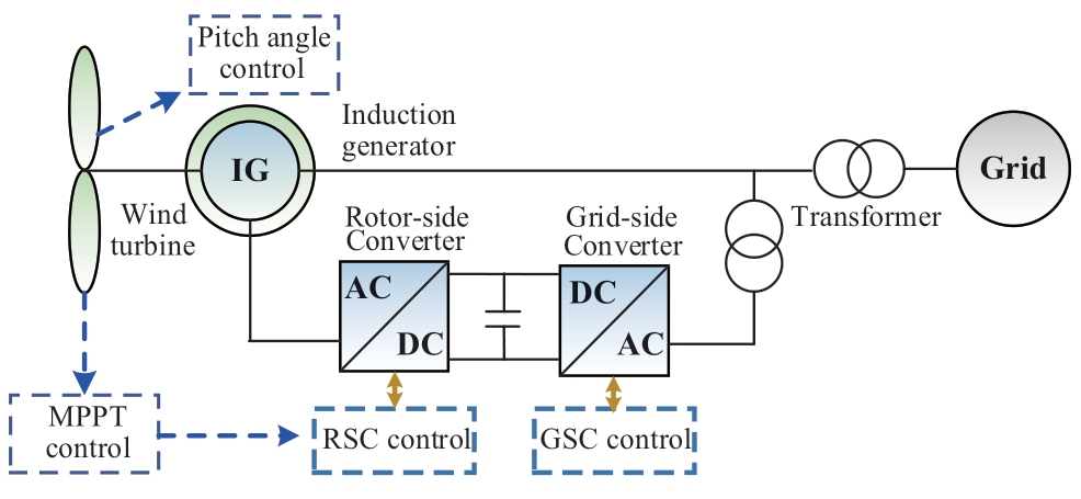
Fig. 1 Topology of the DFIG integrated system
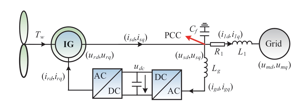
Fig. 2 Equivalent circuit of the DFIG integrated system
where R1/L1 denotes the equivalent resistance or inductance of the power system, L1 denotes the equivalent inductance of the transformer in GSC, and Cf denotes the filter capacitor at the PCC.
1.1 Mathematical modeling of wind turbine
The wind turbine comprises blades and a hub, and its output torque can be expressed as follows [18]:

where Tw denotes the wind turbine output torque, ρ denotes the air density, R denotes the blade radius, Vw denotes the input wind speed, ωt denotes the wind turbine rotational speed, and Cp denotes the wind energy conversion coefficient [18], which is expressed as follows:
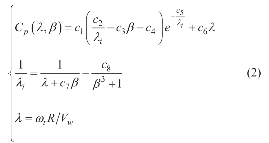
where λ denotes the tip speed ratio, which is determined by the wind turbine characteristics, c1-c8 represent the characteristic constants, and β denotes the pitch angle.
The transmission chain does not significantly affect the grid side, owing to the decoupling control effect of the RSC. Therefore, this study considered only the wind turbine single-mass concentrated model of the transmission chain and incorporated the wind turbine inertia constant into the inertia constant of the IG [22]. The equation of motion for the IG is as follows:

where θr denotes the rotor angle, ωr denotes the rotor mechanical speed, Hr denotes the inertia constant of the IG,and Te denotes the electromagnetic torque of the IG.
The wind turbines of a DFIG typically operate in the MPPT control mode. When Vw exceeds the rated speed Vrated, the wind turbine input power is greater than the power limit, and the wind turbine switches to a constant power control mode. The pitch angle is varied to limit the output power. The control of the pitch angle can be expressed as follows:
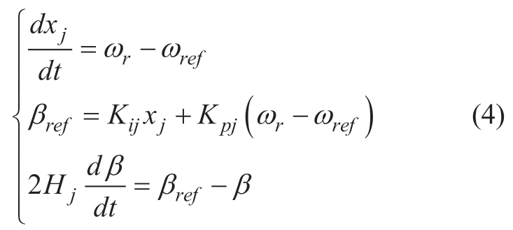
where ωref denotes the reference rotor speed and Hj denotes the inertia constant of the blade. Additionally, the state variable, xj, and the reference of the pitch angle, βref , must be limited to always be greater than zero. Otherwise, there the pitch angle control cannot be initiated in a timely manner.
1.2 Mathematical modeling of IG
The IG adopts a 4th-order model in which the stator/rotor-side current adopts the generator/rotor convention.The voltage and flux equations in the dq-axis are given as follows [23]:
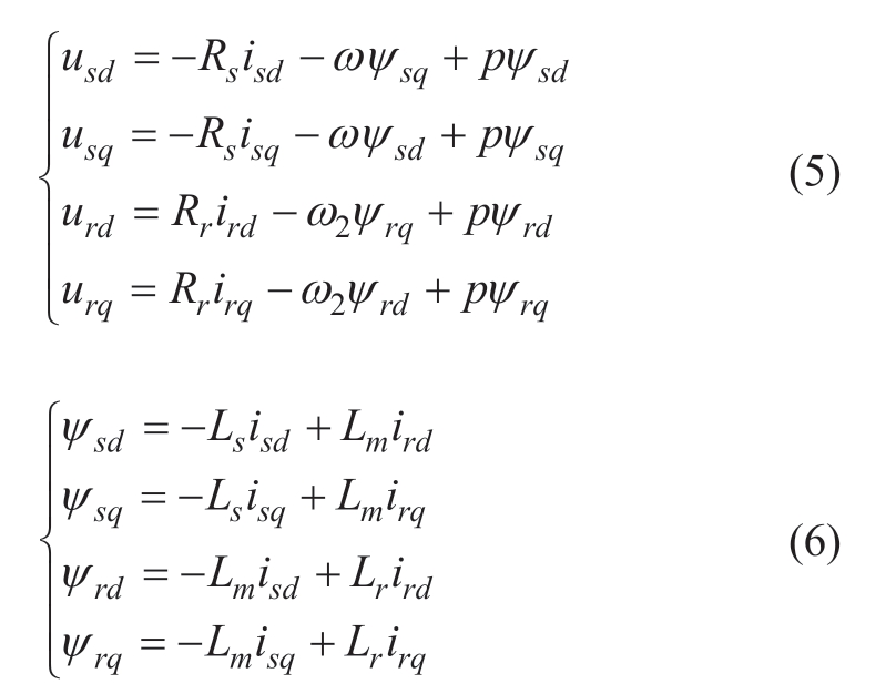
where usd/usq, isd/isq, and ψsd/ψsq denote the d/q-axis components of stator voltage, current and flux; urd/urq, ird/irq, and ψrd/ψrq denote the d/q-axis components of rotor voltage, current, and flux; ω/ω2 (ω2 = ω-ωr) represent the AC power grid/slip angular frequency; and p = d/dt denotes the differential operator. To obtain the state-space equation of the IG, the dq-axis current is considered as the state variable, and Equation (6) is substituted into Equation (5) to eliminate the flux. The correlation between the stator/rotor voltage and current is obtained as follows:
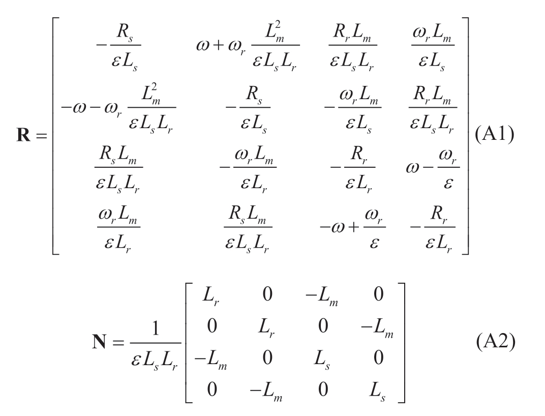
where I = [isd isq ird irq]T, U = [usd usq urd urq]T, and the specific expression of the matrix, R/N, is presented in Appendix A.
The dq-axis components of the stator voltage/current are passed separately through a first-order lag filter to suppress high harmonics as follows:
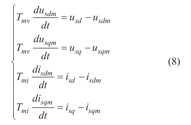
The active/reactive power, Ps/Qs, and electromagnetic torque, Te, on the stator side are expressed as follows:

1.3 Mathematical modeling of converter
1.3.1 Rotor-side converter
The RSC adopts control of the stator voltage-oriented vector and feedforward compensation, including outer loop power control and inner loop current control [24, 25]. The grid-voltage angle and frequency at the PCC were measured using a PLL. Fig. 3 depicts the control strategies for the RSC and the PLL.
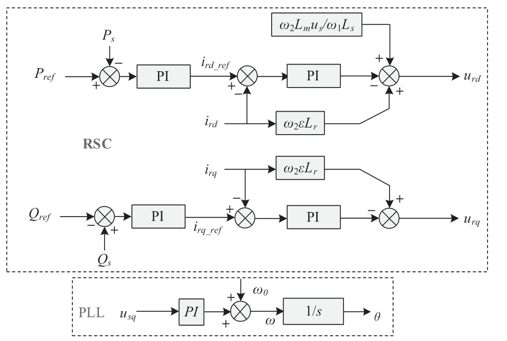
Fig. 3 Control strategy of RSC and PLL
Based on Fig. 3, the mathematical model for the control of the RSC and PLL can be obtained as follows:
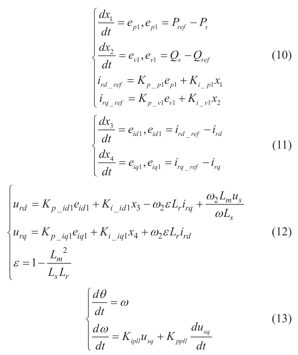
where Pref /Qref denotes the active/reactive power reference of the RSC. x1, x2, x3, and x4 are represent the integral terms of the PI controller, and ep1, ev1, eid1, and eiq1 represent the inputs of the PI controller. Kp and Ki represent the proportional and integral parameters of the PI controller,respectively. ε denotes the leakage coefficient, ω/θ denotes the PLL output angular frequency/angle, and ω0 denotes the rated angular frequency. Pref is determined by using the MPPT controller as follows:

where Cpmax denotes the wind energy conversion coefficient.λ0 denotes the blade tip speed ratio at the maximum power point, γ denotes the gearbox ratio, and Prated denotes the rated capacity of the wind turbine.
1.3.2 Grid-side converter
The GSC adopts the control of a constant DC voltage and unity power factor, where the DC voltage control is achieved by controlling the d-axis current, and unity power factor control is achieved by setting the q-axis current reference, igd_ref, to 0 [26]. Fig. 4 depicts the control strategy for the GSC.
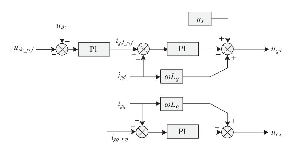
Fig. 4 Control strategy of GSC
The mathematical model of the GSC control strategy can be derived based on Fig. 4 as follows:
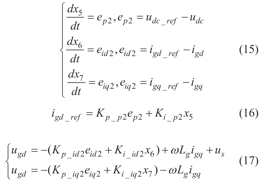
where x5, x6, and x7 represent the integral terms of the PI controller and ep2, eid2, and eiq2 denote the inputs of the PI controller. Kp and Ki represent the proportional and integral parameters of the PI controller, respectively, and ugd and ugq denote the control output voltages of the GSC.
1.3.3 DC line
Considering the dynamic characteristics of the capacitor voltage, the dynamic characteristics of the DC line can be obtained as follows:

where Cdc denotes the DC capacitor, udc denotes the DC voltage, and Pg/Pr denotes the active power output of the GSC/RSC.
1.4 Mathematical modeling of AC power grid
The AC power grid is represented by a Thevenin equivalent circuit, whose strength is reflected by the SCR[27-29]. The base impedance of the AC power grid is Zs =Rs+jXs, where the impedance angle is defined as φ = tan-1(Xs/Rs), and Rs/Xs denotes the equivalent resistance/reactance. The SCR is calculated as follows:
where Vrated /Prated denotes the rated voltage/power of the AC power grid.
The voltage of the AC power grid is transformed by dq decoupling, and the equivalent dq-axis voltages, umd and umq,are expressed as follows:
where Vm represents the voltage amplitude, α0 denotes the initial phase angle (i.e., the angle between the ideal voltage source Vm and the voltage Vs at PCC), and δ = θ-(ω0t+α0)denotes the power angle.
The mathematical model of the AC lines can be obtained as follows:
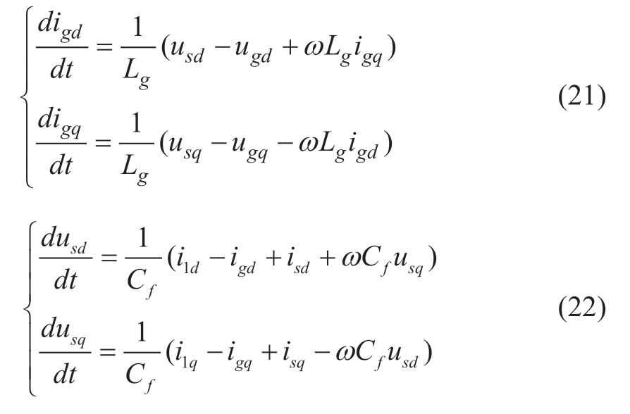
The GSC is directly connected to the AC power grid;therefore, the mathematical model of the AC power grid on the RSC can be written as follows:
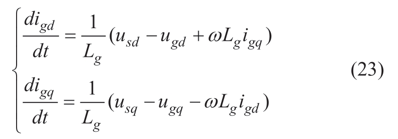
2 Small-signal modeling and analysis of DFIG integrated system
2.1 Detailed small-signal model of the whole system
By summarizing the mathematical models of the above modules, the mathematical model of the entire system(state-space equation) can be obtained as follows:
where x = [ωr, β, xj, isd, isq, ird, irq, isdm, isqm, x1, x2, x3, x4, x5,x6, x7, igd, igq, udc, usd, usq, usdm,usqm, θ, ω, i1d, i1q]T is a 27th state-variable, and u = [Vw, Qref, vdc_ref, igd_ref]T is a 4th inputvariable. The detailed small-signal model of the entire system can be derived by linearizing the state-space equation of the system at a steady-state value (SCR = 4, Vw =8 m/s Qref = 0 pu, vdc_ref = 1 pu, igd_ref = 0 pu), as follows:
where Δx = [Δωr, Δβ, Δxj, Δisd, Δisq, Δird, Δirq, Δisdm, Δisqm,Δx1, Δx2, Δx3, Δx4, Δx5, Δx6, Δx7, Δigd, Δigq, Δudc, Δusd, Δusq,Δusdm, Δusqm, Δθ, Δω, Δi1d, Δi1q]T, and Δu = [ΔVw, ΔQref,Δvdc_ref, Δigd_ref]T. The state matrix, A, is a 27th square matrix,and the dimensions of input matrix, B, are 27 × 4. The specific expression of A/B is not presented here owing to space constraints.
2.2 Comparison verification of the small-signal model
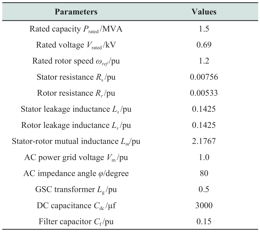
A detailed simulation model of the DFIG integrated system was established using PSCAD/EMTDC, as shown in Fig. 2, and Table 1/2 lists the system parameters are. The accuracy of the established small-signal model is evaluated by comparing the simulation results of the electromagnetic transient model (EMT) with the calculation results of the small-signal model (SS).
Table 1 Wind turbine parameters
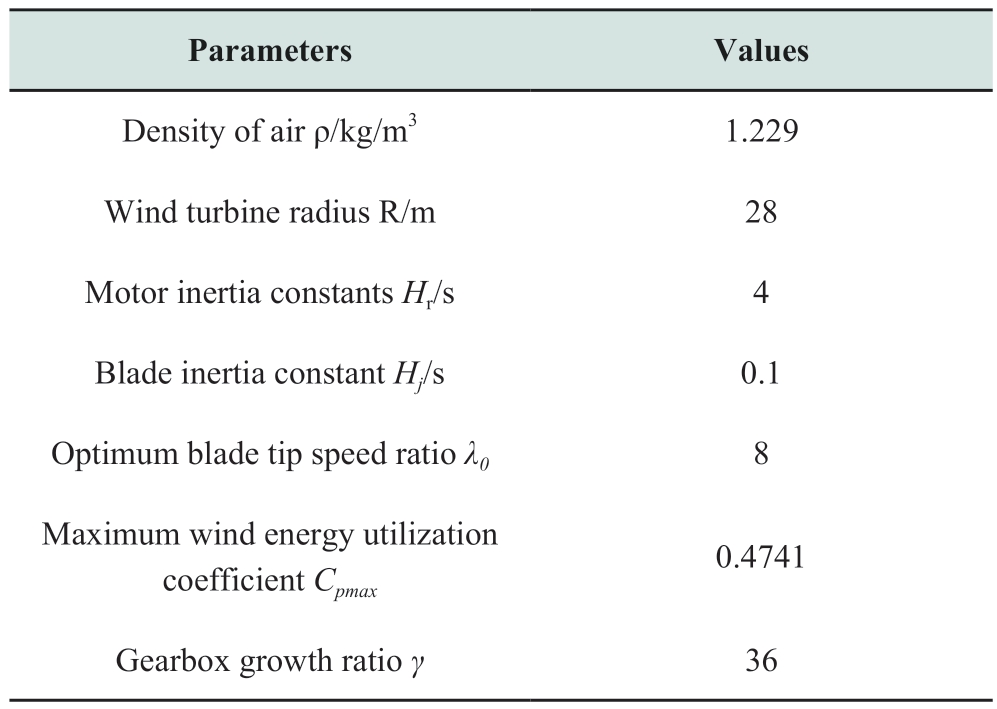
Table 2 Parameters of IG and converter
The following two scenarios were considered to verify the accuracy of the established small-signal model:
• Case 1: At 5 s, Vw steps from 8 m/s to 12 m/s (Vrated).
• Case 2: At 10 s, Vw steps from 12 m/s (Vrate) to 14 m/s.
Fig. 5 (a)-(b) depicts the simulation results for Case 1.
Fig. 5 demonstrates that when the wind speed increases from a low speed (8 m/s) to the rated speed (12 m/s), the dynamic responses of the small-signal modeling and the electromagnetic transient model are relatively consistent.Here, the wind turbine operates in the MPPT control mode,the pitch angle does not work, and the rotor speed increases with an increase in the wind speed, which concurs with the theoretical assumption, demonstrating the accuracy of the small-signal modeling. The established small-signal model is based only on the fundamental frequency characteristics.Therefore, it lacks high-order harmonics when compared with the electromagnetic transient simulation, but the overall trend is consistent.
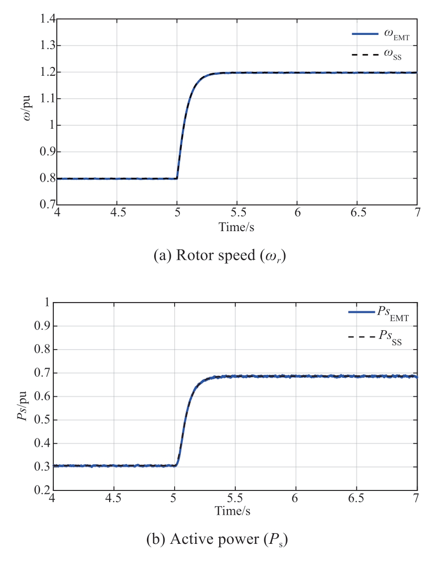
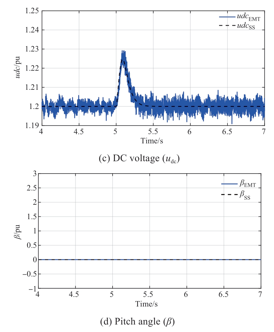
Fig. 5 Dynamic response of Case 1
Figs. 6 (a)-(b) depict the simulation results for Case 2.
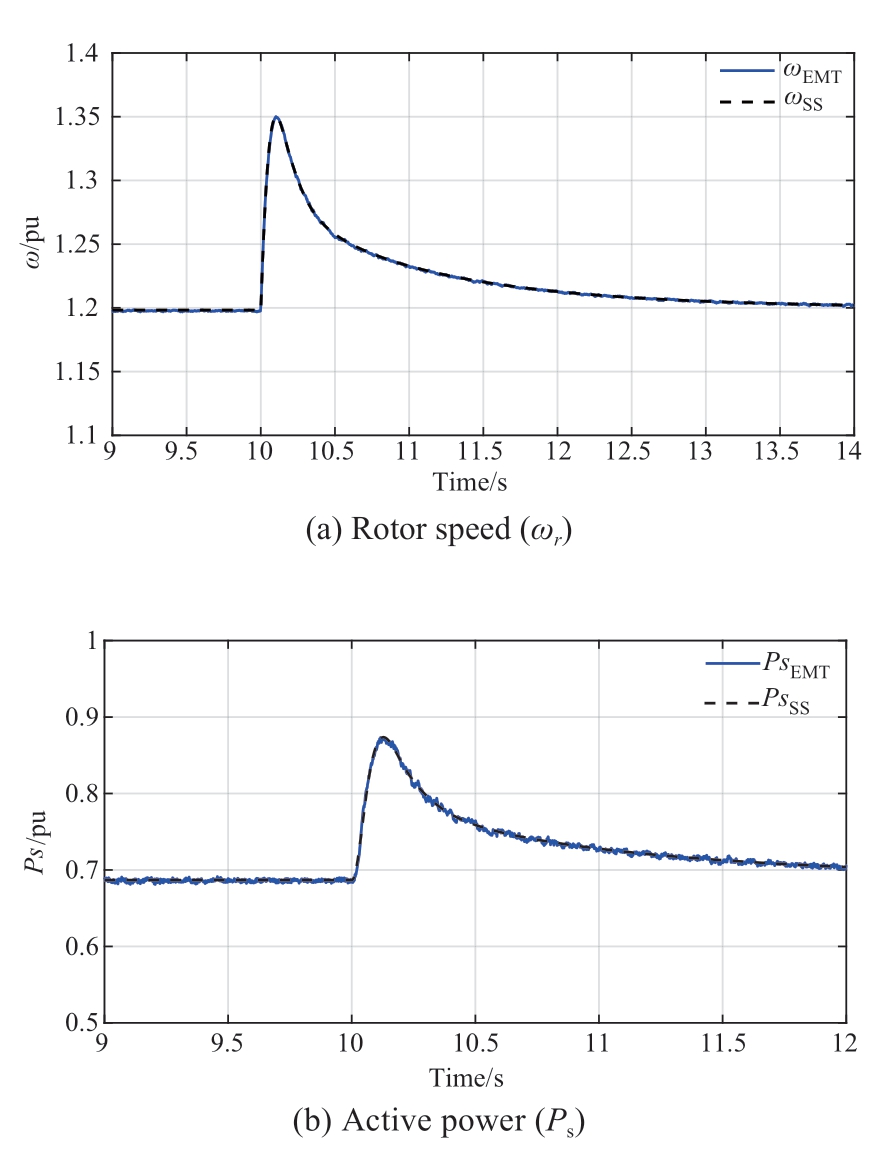
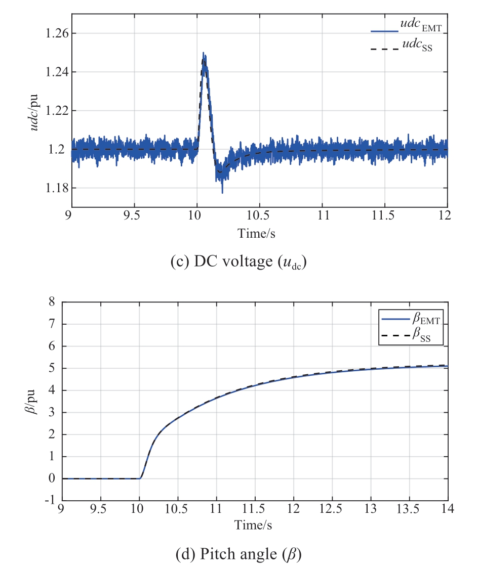
Fig. 6 Dynamic response of Case 2
These results demonstrate that when the wind speed steps up from the rated speed to super speed, the dynamic responses of the small-signal modeling and the electromagnetic transient model remain relatively consistent. Here, the wind turbine operates in the constant power control mode, the pitch angle works, and the active power and rotor speed return to the rated value, which concurs with the theoretical assumption, demonstrating the accuracy of the established small-signal model.
3 Small-signal stability analysis of the system
Based on the detailed small-signal model in Section 3,this section employs root-locus analysis to analyze the effect of the PLL, SCR, and blade inertia (J) on the system smallsignal stability.
The characteristic equation of state matrix A (27thorder) is a high-order polynomial. It is impossible to determine the analytic expression of the correlation between the eigenvalues and the selected parameter. Hence, this study uses a dichotomy to obtain the critical values of the parameters:
The selected parameter is set as variable, m, and the maximum eigenvalue real part function is expressed as follows:
where the eigenvalues of the state matrix, A(m), vary with the variation in m, max denotes the function used to obtain the maximum value, real denotes the function used to obtain the real part of the complex, and eig denotes the function used to obtain the eigenvalues.
f(m) denotes a continuous function. When the system is stable, f(m)<0; when the system is unstable, f(m)>0; when the system is in a critical state, f(m) = 0.
According to the existence theorem of the zero point of a continuous function, a dichotomous judgment program was compiled to approach the critical value. Fig. 7 depicts the flowchart of the program.
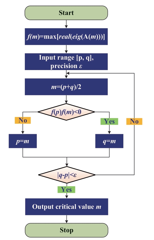
Fig. 7 Flow chart of dichotomy to obtain critical value of parameter
3.1 Impact of PLL on the system small-signal stability
The system initially operates at the rated conditions, and the other parameters remain fixed. Fig. 8 depicts the root locus of the system when the PLL gains KpPLL (KiPLL = 5 ×KpPLL) changes.
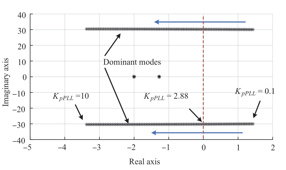
Fig. 8 Root locus of the system when KpPLL steps(SCR = 4, Vw = 8 m/s)
The system-dominant mode gradually approached the imaginary axis with the increase in KpPLL, as shown in Fig. 8.When KpPLL ≤ 2.88, the system exhibited positive real roots and small-signal instability, that is, the critical KpPLL of the system was 2.88.
KpPLL = 2 (the system was unstable) was used for validation to verify the accuracy and effectiveness of the above theoretical analysis. Fig. 9(a) and (b) depicts the system eigenvalues of the established small-signal model when KpPLL = 2.
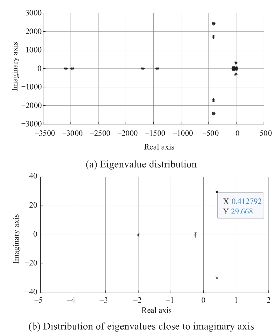
Fig. 9 Eigenvalues of the system when KpPLL = 2
Fig. 9(a)/(b) depicts that the dominant poles of the system at KpPLL = 2 are λ = σ ± jω = 0.4129 ± j29.67, the oscillation period, TSS = 0.2118s (2π/ω), damping ratio, ζSS =![]()
Furthermore, the dominant poles, λ = σ±jω are on the right half plane (which generate the amplification oscillation), and the remaining poles are all on the left half plane (which generate attenuation oscillation). The timedomain equations of the active power (PS) and its deviation(ΔPS) can be derived as follows:

where M denotes the amplitude corresponding to the steadystate value, σ corresponds to the rate of amplitude increase,ω corresponds to the oscillation frequency [30], Ps0 denotes the steady-state value of active power, and θ0 denotes the initial phase angle.
Subsequently, using PSCAD/EMTDC for simulation verification, KpPLL was stepped down from 10 to 2 at 3 s, and the simulation results are illustrated in Fig. 10(a) and (b).
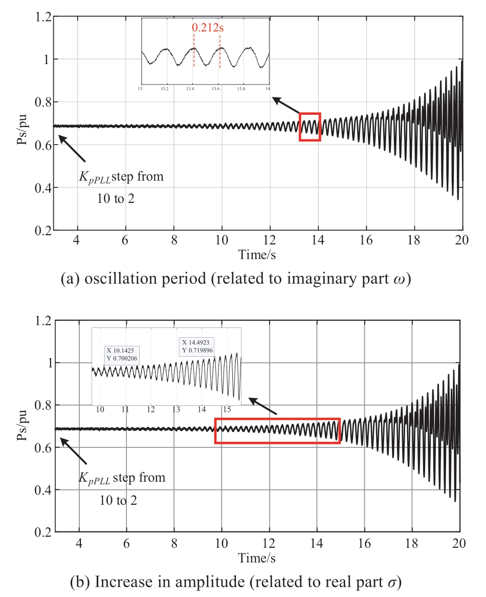
Fig. 10 Dynamic response of the system when KpPLL steps(SCR = 4, Vw = 8 m/s)
The active power (Ps) oscillated with the increasing amplitude after KpPLL steps, as shown in Fig. 10(a). When KpPLL is 2, the oscillation period result of the simulation is TEMT = 0.212 s, which concurs with the small-signal result,TSS = 0.2118 s, demonstrating the effectiveness of the smallsignal analysis of the imaginary part of the dominant poles.
The amplitude of point A/B is MA = 0.70/MB = 0.72, and the time of point A/B was tA = 10.14 s/tB = 14.5 s, as shown in Fig. 10(b). The steady-state value of the active power, Ps0,is 0.696 pu. Based on Equation (27), the following equation can be obtained as follows:
Based on equation (28) the correlation between σ and amplitude can be derived as follows:
Substituting the values of points A and B into equation(29) yields σEMT = 0.411, and based on the simulation results,σEMT and ωEMT = 2π/TEMT = 29.6377 rad/s, the damping ratio of the simulation is ζEMT = -1.4%, which concurs with the small-signal result, ζSS=-1.4%, demonstrating the effectiveness of the small-signal analysis.
This conclusion is based on an analysis of the MPPT control mode (Vw<Vwrated = 12 m/s) of a wind turbine.The following section presents an analysis of the constantpower control mode (Vw>Vwrated = 12 m/s) of a wind turbine. When the other parameters are maintained constant,the wind speed increases from 8 m/s to 14 m/s, the control mode of the wind turbine changes from MPPT control to constant power control, and the root locus of the system when the PLL gains KpPLL changes, as shown in Fig. 11.
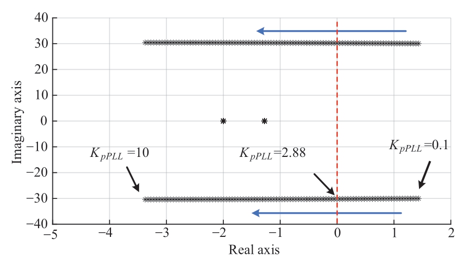
Fig. 11 Root locus of the system when KpPLL steps(SCR = 4, Vw = 8 m/s)
It can be observed from Fig. 11 that its root locus is almost consistent with that in Fig. 8, indicating that the changes in the wind speed (Vw) and control mode of the wind turbine have a negligible effect on the feasible range of the PLL gain (KpPLL). Therefore, when designing the PLL parameters, it is unnecessary to consider the impact of the wind speed and the control mode of the wind turbines on the small-signal stability of the system.
3.2 Impact of SCR on the system small-signal stability
When the other parameters remain unchanged, SCR decreases from 4 to 2, as explained in Section 3.1, and Fig.12 depicts the root locus of the system when the PLL gain,KpPLL, changes.
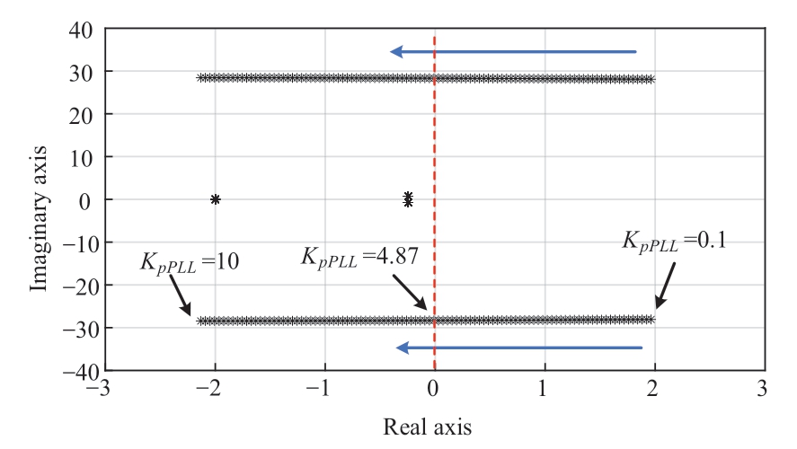
Fig. 12 Root locus of the system when KpPLL changes(SCR = 2, Vw = 8 m/s)
With the increase in KpPLL, the system-dominant mode gradually approached the imaginary axis, as shown in Fig. 12.When KpPLL ≤ 4.87, the system exhibited positive real roots and small-signal instability, that is, the critical KpPLL of the system was 4.87. KpPLL was stepped down from 10 to 3 at 3 s using PSCAD/EMTDC for simulation verification to verify the accuracy of the above analysis. It can be observed from Fig. 13 that the active power (Ps) of the system oscillates with the increase in the amplitude after KpPLL is stepped down. When KpPLL is 3, the dominant pole calculated by using the small-signal model is 0.7723±j28.23, and the oscillation period is 0.2225 s (2π/28.23), which concurs with the electromagnetic transient simulation result of 0.223 s,demonstrating the effectiveness of the small-signal analysis.
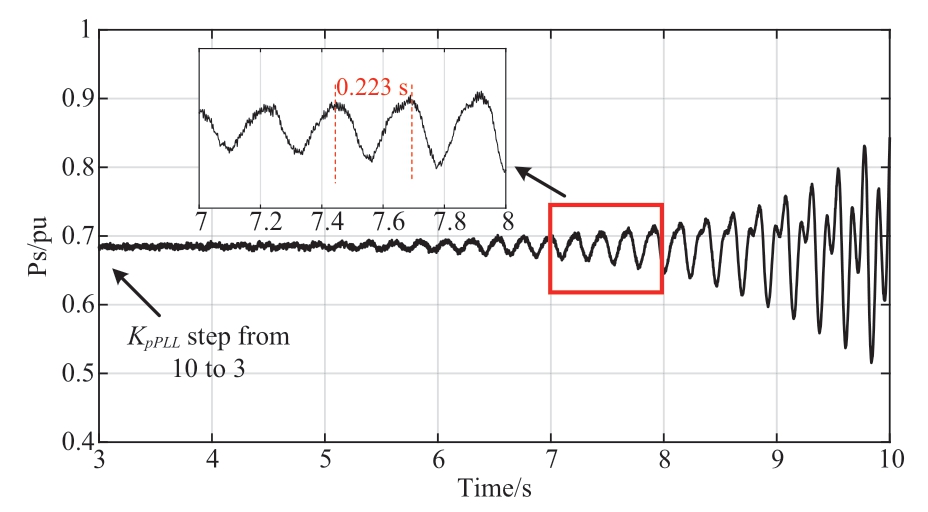
Fig. 13 Dynamic response of the system when KpPLL steps(SCR = 4, Vw = 8 m/s)
It can be concluded from Sections 4.1 and 4.2 that the increase in the PLL gain, KpPLL, can lead to the small-signal instability of the system. The larger the SCR, the smaller the critical stability point and the larger the system stability region.
3.3 Impact of blade inertia on the system smallsignal stability
This section analyzes the impact of the blade inertia, J(J = 2Hj), on the small-signal stability of the system. The system initially operates under the rated conditions; the other parameters remain fixed and Fig. 14 depicts the root locus of the system when J changes.
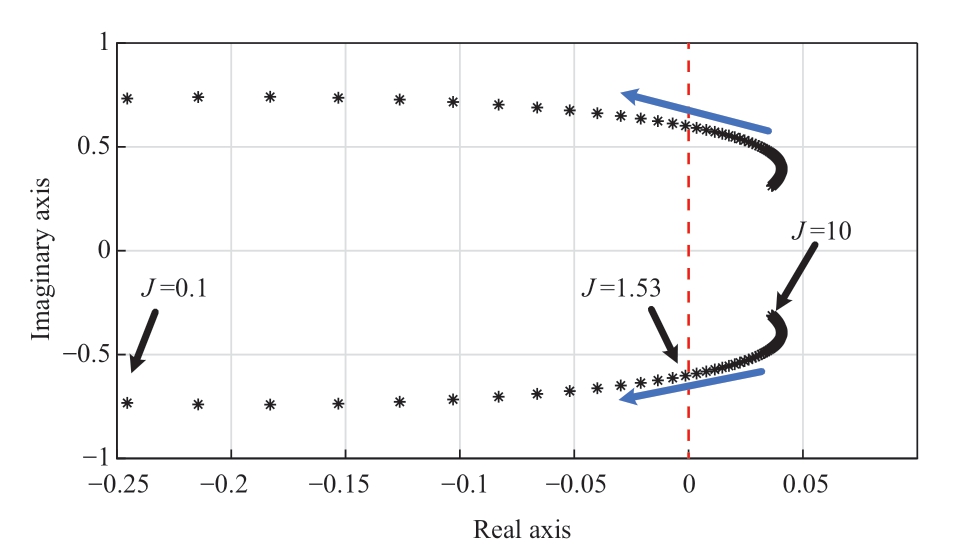
Fig. 14 Root locus of the system when J changes
The system-dominant mode gradually approaches the imaginary axis with the increase in J, as shown in Fig. 14.When J ≥ 1.53, the system exhibited positive real roots and small-signal instability; that is, the critical J value of the system was 1.53. To verify the accuracy of the above analysis, using PSCAD/EMTDC for simulation verification,J was stepped up from 0.2 to 3 at 3 s, and Fig. 15 depicts the simulation results.
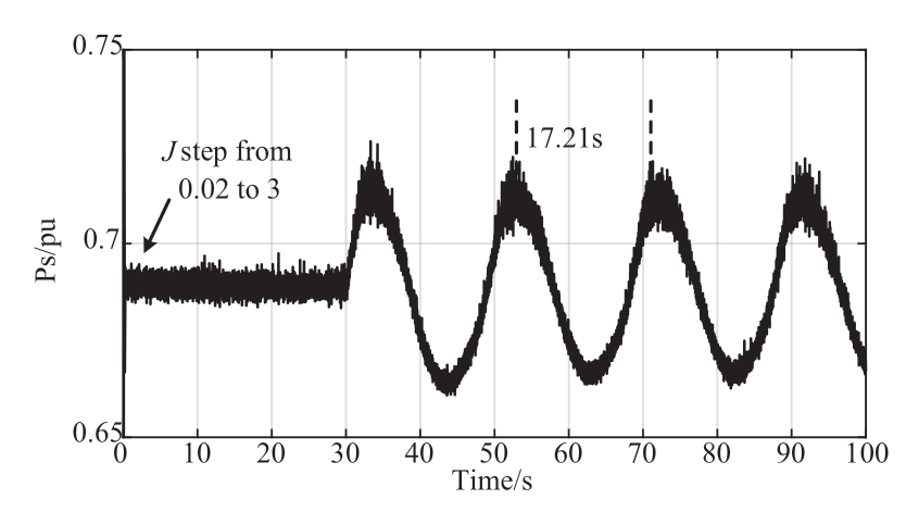
Fig. 15 Dynamic response of the system when J steps
The active power (Ps) of the system exhibited an amplified ultralow-frequency oscillation (0.058 Hz)after J is stepped up, as shown in Fig. 15. When J is 3,the dominant pole calculated by the small-signal model is 0.03371±j0.3674, and the oscillation period is 17.1 s(2π/0.3674), which concurs with the electromagnetic transient simulation result of 17.21 s, thus demonstrating the accuracy of the above analysis. It can be concluded that the large inertia of the wind turbine blades can easily lead to low-frequency or even ultra-low-frequency oscillations,which can adversely affect the system.
4 Conclusion
This study analyzed the modeling and small-signal stability analysis of a DFIG-integrated system. The investigated system comprises four modules: (1) a wind turbine considering MPPT and pitch angle control, (2) an IG, (3) rotor/grid-side converter with the corresponding control strategy, and (4) AC power grid. The detailed small-signal modeling of the entire system is derived by linearizing the dynamic characteristic equation at the steadystate value. Furthermore, we propose a dichotomy method based on the maximum eigenvalue real part function to obtain the critical value of the parameters. Root-locus analysis is employed to analyze the impact of variations in the PLL, SCR, and blade inertia (J) on the system stability.The contributions of this study are as follows:
(1) The accuracy of the derived small-signal model of the entire system was verified by comparing the PSCAD electromagnetic transient simulation model of the nonlinear strong-coupling DFIG integrated system with the dynamic response curve of the linearized small-signal model established in MATLAB under a small disturbance.
(2) The decrease in the PLL gain, KpPLL, can result in system small-signal instability. The larger the SCR, the smaller the critical stability point and the larger the system stability region.
(3) Variations in the wind speed (Vw) and control mode of the wind turbine had a negligible effect on the feasible range of the PLL gain (KpPLL). Therefore, when designing the PLL parameters, it is unnecessary to consider the impact of the wind speed and the control mode of wind turbines on the small-signal stability of the system.
(4) The large inertia of the wind turbine blades can easily produce low-frequency or even ultralow-frequency oscillations that can adversely affect the system.
Appendix A
Acknowledgements
This work was supported by the Key Laboratory of Modern Power System Simulation and Control &Renewable Energy Technology, Ministry of Education(Northeast Electric Power University), Jilin 132012, China(MPSS2023-06).
Declaration of Competing Interest
We declare that we have no conflict of interest.
References
[1] Catalán P, Wang Y B, Arza J, et al. (2023) A comprehensive overview of power converter applied in high-power wind turbine:Key challenges and potential solutions. IEEE Transactions on Power Electronics, 38(5): 6169-6195
[2] Du W J, Wang Y, Wang H F, et al. (2020) Analytical examination on the amplifying effect of weak grid connection for the DFIGs to induce torsional sub-synchronous oscillations. IEEE Transactions on Power Delivery, 35(4): 1928-1938
[3] Wang S, Hu J B, Yuan X M (2015) Virtual synchronous control for grid-connected DFIG-based wind turbines. IEEE Journal of Emerging and Selected Topics in Power Electronics, 3(4): 932-944
[4] Blaabjerg F, Teodorescu R, Liserre M, et al. (2006) Overview of control and grid synchronization for distributed power generation systems. IEEE Transactions on Industrial Electronics, 53(5):1398-1409
[5] Bray J W, Fair R, Haran K (2014) Wind and ocean power generators. IEEE Transactions on Applied Superconductivity,24(3): 1-7
[6] Chi Y, Li W, Wu Q, et al. (2020) Coordinated voltage control of renewable energy power plants in weak sending-end power grid.Global Energy Interconnection, 3(4): 365-374
[7] Blaabjerg F, Ma K (2017) Wind energy systems. Proceedings of the IEEE, 105(11): 2116-2131
[8] Erlich I, Shewarega F, Feltes C, et al. (2013) Offshore wind power generation technologies. Proceedings of the IEEE, 101(4): 891-905
[9] Yuan X M (2013) Overview of problems in large-scale wind integrations.Journal of Modern Power Systems and Clean Energy,1(1): 22-25
[10] Song Y P, Blaabjerg F (2017) Overview of DFIG-based wind power system resonances under weak networks. IEEE Transactions on Power Electronics, 32(6): 4370-4394
[11] Xu Y, Gao T(2022) Sub-synchronous frequency domainequivalent modeling for wind farms based on rotor equivalent resistance characteristics. Global Energy Interconnection, 5(3):293-300
[12] Lee J, Muljadi E, Srensen P, et al. (2016) Releasable kinetic energy-based inertial control of a DFIG wind power plant. IEEE Transactions on Sustainable Energy, 7(1): 279-288
[13] Miao Z X, Fan L L, Osborn D, et al. (2009) Control of DFIGbased wind generation to improve interarea oscillation damping.IEEE Transactions on Energy Conversion, 24(2): 415-422
[14] Cardenas R, Pena R, Alepuz S, et al. (2013) Overview of control systems for the operation of DFIGs in wind energy applications.IEEE Transactions on Industrial Electronics, 60(7): 2776-2798
[15] Edrah M, Lo K L, Anaya-Lara O (2015) Impacts of high penetration of DFIG wind turbines on rotor angle stability of power systems. IEEE Transactions on Sustainable Energy, 6(3):759-766
[16] Sun L, Zhao X W (2022) Impacts of phase-locked loop and reactive power control on inertia provision by DFIG wind turbine.IEEE Transactions on Energy Conversion, 37(1): 109-119
[17] Qin C, Yu Y X (2013) Small signal stability region of power systems with DFIG in injection space.Journal of Modern Power Systems and Clean Energy, 1(2): 127-133
[18] Liu J, Yao W, Wen J Y, et al. (2020) Impact of power grid strength and PLL parameters on stability of grid-connected DFIG wind farm. IEEE Transactions on Sustainable Energy, 11(1): 545-557
[19] Jia Y B, Huang T, Li Y B, et al. (2020) Parameter setting strategy for the controller of the DFIG wind turbine considering the smallsignal stability of power grids. IEEE Access, 8: 31287-31294
[20] Hu J B, Huang Y H, Wang D, et al. (2015) Modeling of gridconnected DFIG-based wind turbines for DC-link voltage stability analysis. IEEE Transactions on Sustainable Energy, 6(4):1325-1336
[21] Gautam D, Vittal V, Harbour T (2009) Impact of increased penetration of DFIG-based wind turbine generators on transient and small signal stability of power systems. IEEE Transactions on Power Systems, 24(3): 1426-1434
[22] Mei F, Pal B (2007) Modal analysis of grid-connected doubly fed induction generators. IEEE Transactions on Energy Conversion,22(3): 728-736
[23] Tang W, Hu J B, Chang Y Z, et al. (2018) Modeling of DFIGbased wind turbine for power system transient response analysis in rotor speed control timescale. IEEE Transactions on Power Systems, 33(6): 6795-6805
[24] Zhao M Q, Yuan X M, Hu J B (2018) Modeling of DFIG wind turbine based on internal voltage motion equation in power systems phase-amplitude dynamics analysis. IEEE Transactions on Power Systems, 33(2): 1484-1495
[25] Zhu R W, Chen Z, Tang Y, et al. (2016) Dual-loop control strategy for DFIG-based wind turbines under grid voltage disturbances. IEEE Transactions on Power Electronics, 31(3):2239-2253
[26] Mohammadi J, Vaez-Zadeh S, Afsharnia S, et al. (2014) A combined vector and direct power control for DFIG-based wind turbines. IEEE Transactions on Sustainable Energy, 5(3): 767-775
[27] Zhou J Z, Ding H, Fan S T, et al. (2014) Impact of short-circuit ratio and phase-locked-loop parameters on the small-signal behavior of a VSC-HVDC converter. IEEE Transactions on Power Delivery, 29(5): 2287-2296
[28] Wang P Y, Liu P C, Gu T M, et al. (2023) Small-Signal Stability of DC Current Flow Controller Integrated Meshed Multi-Terminal HVDC System. IEEE Transactions on Power Systems,38(1): 188-203
[29] Li Y, Fu L, Li Q, et al. (2023) Small-signal modelling and stability analysis of grid-following and grid-forming inverters dominated power system. Global Energy Interconnection, 6(3):363-374
[30] Kundur P, Balu N, Lauby M (1994) Power System Stability and Control. New York: McGrawhill
Received: 17 January 2023/ Accepted: 14 June 2023/ Published: 25 August 2023
 Puyu Wang
puyu.wang@hotmail.com
Tianming Gu
tianming.gu@qq.com
Dingyuan Liu
dingyuan.liu_1@qq.com
Ao Sun
ao.sun.njust@qq.com
Dejian Yang
yangdejian@neepu.edu.cn
Gangui Yan
yangg@neepu.edu.cn
2096-5117/© 2023 Global Energy Interconnection Development and Cooperation Organization. Production and hosting by Elsevier B.V. on behalf of KeAi Communications Co., Ltd. This is an open access article under the CC BY-NC-ND license (http: //creativecommons.org/licenses/by-nc-nd/4.0/ ).
Biographies

Tianming Gu received the B.Eng. degree from Nanjing University of Science and Technology(NUST), China in 2020, both in electrical engineering. He is currently pursuing the Ph.D.degree at the same university. His research interests include stability analysis and control of the power electronics applications in power systems and renewable energy integration.

Puyu Wang (S’13–M’15) is currently an Associate Professor in Department of Electrical Engineering, School of Automation at Nanjing University of Science & Technology (NUST),China. His research interests include control and protection of synchronous condenser,HVDC technology, DC–DC converters, grid integration of renewable energy, and power electronics applications in power systems.

Dingyuan Liu received the B.Eng. and M.Sc.degrees from Nanjing University of Science and Technology (NUST), China in 2020 and 2023,respectively, both in electrical engineering. His research interests include stability analysis and control of the power electronics applications in power systems and renewable energy integration.

Ao Sun received the B.Eng. degree from Nanjing University of Science and Technology (NUST),China in 2023, in electrical engineering. He is currently pursing the M.Sc. degree at the same university. His research interests include stability analysis and control of the power electronics applications in power systems and renewable energy integration.

Dejian Yang (S’15–M’20 ) is currently a Lecturer with the School of Electrical Engineering, Northeast Electric Power University, Jilin City, China. His research interest is in the development of control systems for renewable energy sources.

Gangui Yan is the Professor with Northeast Electric Power University, Jilin City, China.His research interests include power electronic,power system, wind power generation, steadystate operation analysis, and power electronic technology.
(Editor Dawei Wang)
