0 Nomenclature
pFe iron loss(W)
p1/50 iron loss coefficient
ΔP pressure difference(W)
L length of the stator core(m)
b wall thickness(m)
n number of water cold plates
pwater energy loss of cooling water(W)
1 Introduction
As the core component of power systems, motors are widely used in various fields in modern society.With the rapid development of industrial technology, the singlemachine capacity of motors continues to increase, and a type of high-loss-density motor has emerged.The highspeed permanent magnet synchronous motor(PMSMs)is small and has the characteristics of high power density and high loss density and the rotating speed was usually above 10000 rpm.It is a typical high-loss-density motor and has a wide range of applications.
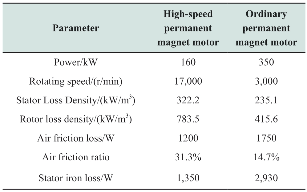
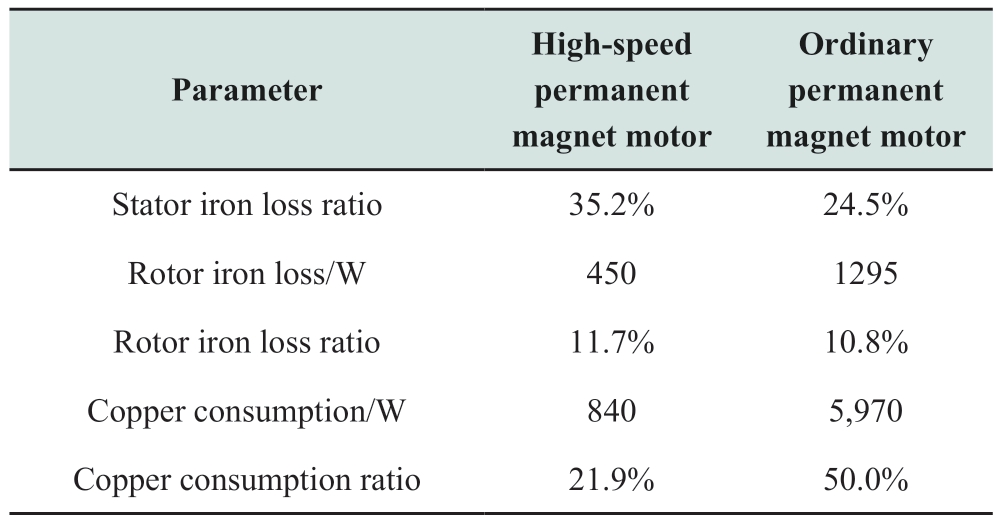
High-speed PMSMs offer many advantages, such as small size, light weight, and high power density.However,there are problems with high loss density and difficult heat dissipation.Compared with ordinary permanent-magnet motors, high-speed permanent-magnet motors have higher operating frequencies and rotational speeds.Consequently,its loss distribution is different from that of ordinary permanent magnet motors, and its loss parameters are compared in Table 1 [1].
The high-speed PMSM has a high operating frequency and high loss density, resulting in a high temperature increase.The temperature rise of the motor is an important factor that limits its capacity.In case of a very high temperature increase,the permanent magnet may be demagnetized or the insulation between the windings may be damaged.Consequently, the reliable operation of the motor is affected.Therefore, the design of high-efficiency cooling systems for high-speed PMSM is particularly important.
Table 1 Comparison of loss parameters between high-speed and ordinary permanent magnet motors
continue
Most high-speed PMSMs adopt the air-water mixing cooling method.Cooling air is introduced into the air gap of the motor to cool the interior of the rotor and stator.The external water jacket of the motor primarily cools the motor stator.Because the heat dissipation efficiency of air cooling is much lower than that of water cooling, the heat dissipation problem inside high-speed motors must be solved urgently.Several studies have focused on the cooling system of the motor, which has led to continuous improvement in the efficiency of the cooling system of the motor.Reference [2] shows the motor temperature fields of different cooling methods for a 1.12 MW highspeed permanent magnet motor were analyzed, including water cooling and air cooling, axial and radial ventilation,spiral water channels, reentrant water channels, and other cooling methods.In reference [3], the effect of different numbers of channels and the form of the spoiler on the cooling effect were analyzed, and the correctness of the finite volume method was verified through experiments.Aurelie F and Daniel L designed a water cold plate with water circulation only in the yoke, and the influences of the external environment, water cold plate arrangement, and lamination coefficient on the cooling effect were studied.It was concluded that the cooling efficiency of the structure is the most sensitive to changes in the external environment [4].
A hybrid cooling structure and control system were designed for electric vehicle motors in reference [5].The structure included an outer spiral water jacket and an air-cooled part comprising a heat pipe and fan.The cooling structure was designed according to the different working conditions of the electric vehicle.In reference[6], the flow state of the cooling medium in the motor and the temperature distribution of the motor based on the fluid-solid coupling heat transfer theory were analyzed.Computational fluid dynamics and the temperature field were used to analyze the flow velocity, pressure difference between the inlet and outlet, temperature distribution of the motor squirrel cage, and winding.
Reference [7] proposed a new iron loss calculation model that considered multiple physical fields, such as high frequency, temperature, and stress.First, the magnetic,temperature, and stress fields were analyzed using the finite element method, and then the iron loss of the silicon steel sheet and prototype was calculated using the proposed model.Further, the accuracy of the proposed iron-loss model was verified using experimental test measurements on the prototype.Based on a multi-physics simulation analysis, Wang T Y proposed a temperature calculation method considering the nonlinear change of material properties with temperature, and a fluid-solid-heat coupled heat transfer calculation model was established.Under basic assumptions and corresponding boundary conditions, the coupled field was calculated using the finite volume method[8].Further, the inverse iteration method was used to obtain the heat transfer coefficient of the water pipe surface, and an experiment was designed to verify the correctness of the coupled field solution method.
In reference [9], for a widely used reentrant channel structure for a PMSM, a fluid-structure coupling temperature field and a numerical simulation model of the flow field were established to accurately calculate the temperature rise and pressure drop of the motor.Reference[10] considered the linear function relationship between the derivative of the node temperature and the node temperature and heat loss in the discrete state equation, a multiple linear regression method was proposed to identify the parameters of the state equation offline.The state equation parameters were determined and the motor rotor temperature was estimated based on the state equation.The influence of different sizes of cooling teeth on the cooling performance of high torque motor was studied by simulation, and the optimal size and cooling performance of cooling teeth are obtained [11].
In reference [12], a three-dimensional (3D) temperature field simulation model was established for a PCB-winding disk-type ironless PMSM.The heating of the motor and the temperature rise of the various parts of the motor were studied.Consequently, the temperature rise of the motor was reduced by increasing the contact area between the motor casing and PCB stator.3D thermal simulation model was established, and the temperature increase of the motor under different working conditions was analyzed [13].The optimal flow rate at the inlet of the motor water channel was selected through comparisons and analysis of the temperature rise of the motor with different cooling water flow rates.
Reference [14] aiming at a 200kW marine high-speed PMSM, a 3D integrated motor model was established by simplifying the basic assumptions and boundary conditions.A cooling water channel of the motor was composed of resin injection molding, and the cooling liquid could enter between the windings, thus achieving a better cooling effect[15].In reference [16], the cooling channel of an axial flux motor was proposed, and the loss and temperature fields of the motor were analyzed.In reference [17], the related contents of oil injection cooling were studied, and the influence of nozzle type and nozzle number on the motor temperature rise was analyzed.A water-cooling structure was designed in reference [18], the cooling liquid circulated at the notch and the other parts were filled with potting glue, and the cooling effect of the structure was verified experimentally.
Reference [19] compared three different oil-cooling structures of an axial flux motor, it was shown that two parallel structures can achieve a higher cooling effect.In reference [20], the winding was wrapped by resin, and a baffle was arranged at the end of the motor such that the cooling liquid could circulate in the groove.Consequently, direct heat convection with the winding improved the heat dissipation performance of the motor.Advanced cooling system comprised several water-cold plates radially inserted into the core laminations, which can reduce the winding temperature by 20 °C compared with WJ under rated conditions [21].In reference [22], three designs were studied numerically.The special cooling jacket was slightly superior; however, it also resulted in a higher pressure drop and required more pumping power to achieve a low resistance.
Reference [23] showed one end of the heat pipe was inserted into the stator yoke, and the other end was outside the motor and connected with the aluminum radiator.Based on a 3D transient temperature field simulation, the influence of the axial size of the radiator and the thermal conductivity of the heat pipe on the temperature rise of the motor was analyzed.A packaged air-cooling system was developed,wherein the cooling air circulated inside the motor and exchanged heat convection with the inner wall of the casing, which effectively cooled the rotor [24].The cooling performance of a single conductor phase using EGW50/50 or water as coolant was studied, and the results showed that the cooling design was excellent, when the maximum temperature rise of the conductor was only 56.9℃, the power consumption was 710 W [25].
In reference [26], a new type of forced-air cooling technology assisted by a heat pipe was proposed.The heat pipe provided an auxiliary heat dissipation path for the winding and stator, which had reference significance in improving the operational reliability of the AFPM synchronous motor.In reference [27], an air-water mixed cooling system was proposed, and the finite element calculation was first used to determine the winding loss in the stator.Further, the influence of airflow velocity, airflow turbulence, and liquid velocity was discussed by CFD simulation.In reference [28], a flexible and detailed lumped parameter thermal network (LPTN) for a cooling system was proposed, wherein the LPTN was used to optimize the size and position of the groove channel to obtain the maximum thermal benefit.
Wu SN proposed a cooling structure of a water cold plate, and the influence of the thickness of the water cold plate and the number of water channels in the water cold plate on the heat dissipation capacity of the water cold plate was analyzed using theoretical and computational fluid dynamics methods [29].Reference [30] proposed an evaporative cooling scheme for a motor was proposed.The Novec-7200 dielectric coolant was used as the working fluid in the motor.The motor was half submerged by the coolant,and the end windings were also cooled by evaporation.In reference [31], heat transfer characteristics of ten typical thermal interface materials were studied by design experiments, and the selected thermal interface materials was applied to the stator winding of high-voltage motor belt to evaluate their influence on the cooling performance of the motor under different cooling conditions.
In this study, using a high-speed PMSM as an example,and aiming at solving its high loss density and difficulty in internal heat dissipation, the placement of a water cold plate cooling structure in the middle of the motor stator was proposed.With this structure, the cooling liquid was closer to the winding such that the motor could dissipate heat more quickly and thus improve the power density of the motor.
2 Design of motor cooling scheme using water cold plate
To address the problem of difficulty in heat dissipation inside a high-speed permanent magnet synchronous motor,a water-cold plate structure was proposed.The internal structure of a cold plate is illustrated in Fig.1.

Fig.1 Internal waterway structure of water cold plate
The designed water cold plate was embedded between the stator silicon steel sheets.The water cold plate and the iron core can be connected by bolts, or the casing can exert a pre-tightening force to fix them.The cooling water circuit circulated in the water-cold plate, stator yoke, and teeth.
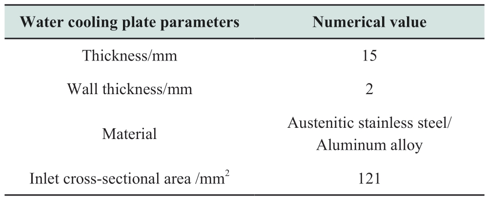
The heat generated by the motor teeth and windings was exported from the inside of the motor, which is better for the inside of the motor cooling.Its specific parameters are listed in Table 2.
Table 2 The main parameters of the water cold plate
The structure of the motor cooled by a cold-water plate is shown in Fig.2.Cooling water entered the water cold plate from the water inlet (upper part of the motor),conducted heat exchange through the water cold plate inside the motor, and then flowed out from the water outlet (lower part of the motor).The structural model used two cold-water plates.For motors with different axial lengths, different numbers of water cold plates must be selected to satisfy their temperature increase requirements.
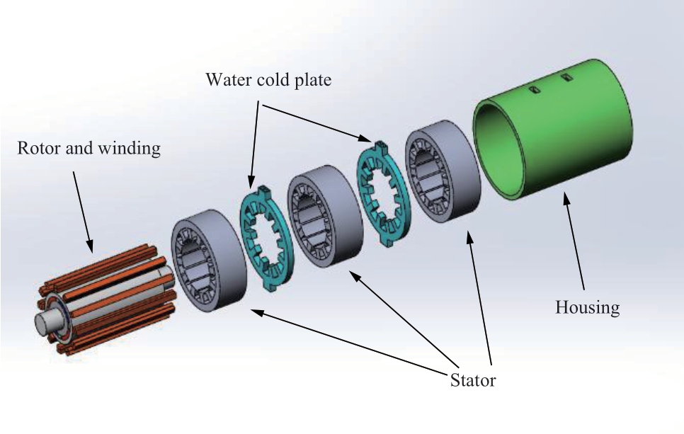
Fig.2 High-speed permanent magnet synchronous motor with water cold plate
3 Analysis of factors influencing the cooling performance of water cold plate
Various factors affect the cooling effect of the watercold plate, including the flow of cooling water, thickness of the water-cold plate, ambient temperature, wall thickness,and material of the water-cold plate.Because the heat transfer rate between the fluid and solid is mainly affected by the temperature difference, fluid velocity, and contact area between them, this section focuses on three main factors: the flow of cooling water, thickness of the water cold plate, and motor loss density.The finite element analysis method was used to study the influence of each parameter on the cooling effect of the water-cold plate.For a water-cold plate with different thicknesses and cooling water flow, the cooling capacity of the motor was different.This study utilized the effective cooling length to measure the cooling capacity of different specifications of a water-cold plate.The effective cooling length is the distance from the side of the water cold plate to the farthest point of the stator, which can satisfy the temperature rise conditions(The temperature rise condition of the stator was <60 °C).
3.1 Influence of cooling water flow on cooling effect of water cold plate
First, maintaining the key conditions, such as air speed,temperature, and loss density of each part constant in the environment where the motor was located, the flow of cooling water was gradually increased and the effective cooling length corresponding to each flow was recorded.The relationship curve between the effective cooling length and cooling water flow was obtained, as shown in Fig.3.As evident, increasing the cooling water flow significantly improved the cooling effect of the water cold plate in the lower flow range, which was 0-6 L/min.Beyond this range, the flow continued to increase; however,the cooling effect did not significantly increase.Therefore,in the process of designing and optimizing the cooling system of the motor, increasing only the cooling water flow may not improve the cooling system performance.
3.2 Influence of thickness on cooling effect of water cold plate
Keeping the water flow and other conditions that affect the temperature rise of the motor unchanged, the thickness of the water cold plate was gradually increased, and the effective cooling length corresponding to each thickness was recorded.The relationship curve between the effective cooling length and water cold plate thickness is shown in Fig.4.
When the cooling water flow was constant, as the thickness gradually increased, the water flow speed inside the water cold plate decreased.In addition, its cooling effect decreased continuously and finally tended to stabilize.
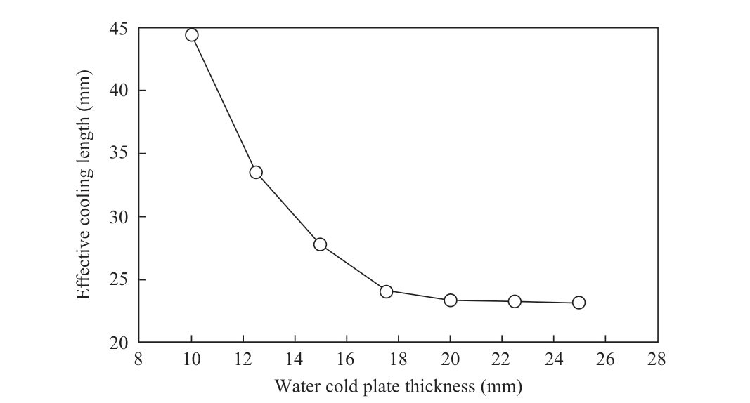
Fig.4 Relationship curve between effective cooling length and water cold plate thickness
3.3 Influence of motor loss density on cooling effect of water cold plate
Similarly, keeping other conditions, such as ambient temperature, cooling water flow, and water cold plate parametersunchanged, themotorloss density wasvariedin the range 50-200kW/m3and the effective coolinglength corresponding to each loss density was recorded.The relationship curve between the effective cooling length and motor loss density is shown in Fig.5.
As can be seen in Fig.5, the effective cooling length of the water-cold plate gradually decreased with increase in the motor loss density.Therefore, high-density motors must be equipped with more efficient cooling systems to satisfy their own temperature rise requirements.
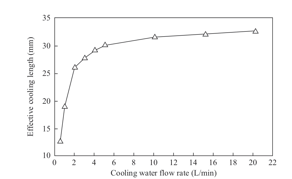
Fig.3 Relationship curve between effective cooling length and cooling water flow
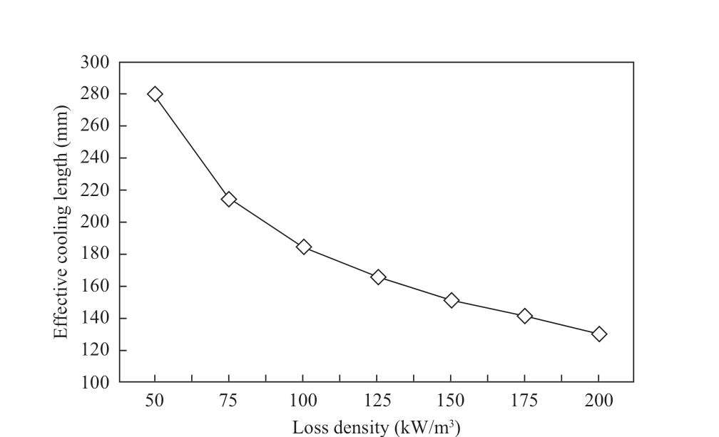
Fig.5 Relationship curve between effective cooling length and motor loss density
4 Comparative analysis of two cooling structures
To study the cooling effect of the water cold plate cooling structure, the finite element analysis method was used to compare the new structure with the widely used outer spiral water-jacket structure.
4.1 Simulation model and boundary conditions
When making a comparison, the principle of the controlled variable method must be followed.While changing only the cooling structure of the motor, the simulation conditions of the two models must be kept consistent.With the total length of the motor remaining constant, geometric models with the water cold plate structure and spiral water jacket were established, as shown in Fig.6.
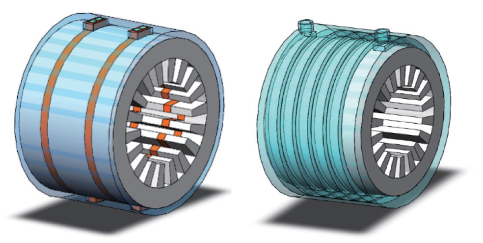
Fig.6 Water cold plate motor and Spiral water jacket motor structure model
Because the total length of the motor remains unchanged, the length of the stator core was reduced owing to the embedding of the water-cold plate between the stators.To maintain the original electromagnetic performance of motor, the magnetic load of the motor must be increased to a certain proportion.When the influence of the saturation of the magnetic circuit is ignored, the iron loss of the motor is
where pFe is the iron loss in the motor core, p1/50 is the iron loss coefficient, f is the motor operating frequency, β is the frequency index, and Bm is the magnetic induction intensity.
The total length of the iron core was 165 mm and the total thickness of the cold-water plate was 25 mm.
After the stator was embedded in the water cold plate,the total volume of the stator core was reduced to 0.85 times of the original; thus, the magnetic load increased by a factor of 1.18 times.
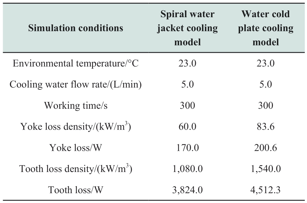
Referring to Eq.(1), the relationship between the iron loss and magnetic induction is quadratic, and the motor loss density increased by a factor of 1.39 times.Because the total volume of the iron core was reduced by a factor of 0.85 times, the total loss of the iron core was 1.18 times of the original.The motor loss density was increased by 1.39 times of the original, and the total loss was 1.18 times of the original.Simultaneously, a consistent external ambient temperature and cooling water flow must be maintained.The simulation conditions are listed in Table 3.
Table 3 Simulation initial conditions
4.2 Solution and result analysis
Based on the above models and boundary conditions,the 3D temperature field distributions of the two models were obtained, as shown in Fig.7.The temperature fields of the two structures showed that the motor tooth temperature was significantly lower with the water cold plate cooling structure than with the spiral water jacket structure, indicating that this structure can better cool the motor interior.Following post-processing analysis, the maximum temperature of the stator core of the spiral water jacket structure was 118.2 ℃, whereas that of the water cold plate structure was 87.9 ℃, which is 30.2 ℃ lower than the former.Further, the average stator temperature of the water cold plate structure was 21.3 ℃ lower than that of the spiral water jacket structure.
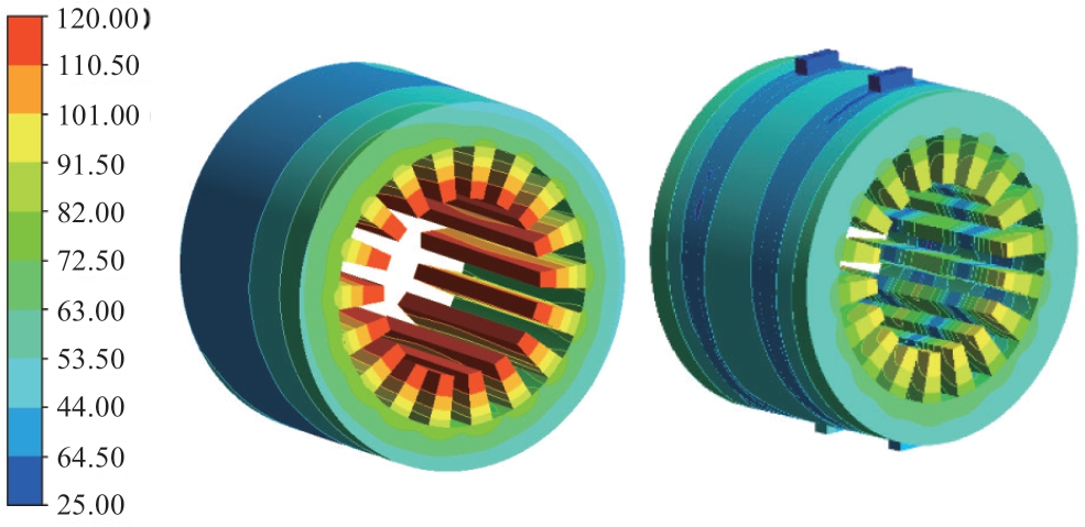
Fig.7 Water cold plate motor and Spiral water jacket motor
temperature field
Based on the temperature field distribution of the two structures, the temperature distribution of the stator core of the spiral water jacket structure showed that the internal temperature was relatively high, whereas the external temperature was relatively low.The temperature distribution of the stator core of the water cold plate structure was such that the part away from the water cold plate was high,whereas that in the water cold plate is low.
To describe the temperature distribution characteristics of the two models more intuitively, the same tooth of the two models was selected, and axial and radial lines were drawn through the center point of the tooth, which were used to determine the relationship between the temperature and the axial and radial positions of the motor.Among them, 30 and 20 points were considered for the axial and radial temperature sample points, respectively.
The relationship between the temperature and the motor axial and radial positions is shown in Figs.8 and 9.The temperature increase of the motor with the water cold plate structure was small, thereby proving that the motor cooling structure using water cold plates exhibited a better cooling performance.
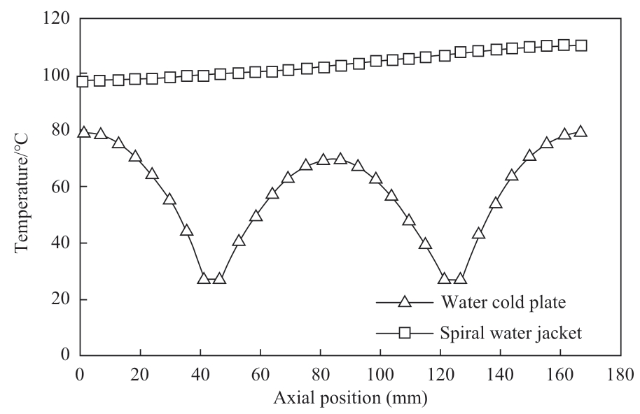
Fig.8 Comparison of axial temperature distribution of two structures
4.3 Comparative analysis of mass and volume of two structure motors
When designing the cooling system of the original motor, the structure of the motor will be changed, and the performance of the motor will be affected at the same time.Therefore, the objective physical indexes such as the quality, volume, size and cost of the motor should be weighed against the performance indexes such as the electromagnetism, stress and vibration noise of the motor.With the development of motor towards high power density,high integration and high reliability, the index margin of motor in all aspects is getting smaller and smaller.Compared with the motor with a traditional external spiral water jacket cooling structure, the overall outer diameter of the motor with the water cold plate structure was reduced, the overall volume was reduced accordingly,and the number of silicon steel sheets in the stator core was also reduced.Therefore, the consumption of various materials used in the manufacture of motors changed accordingly.The calculation results for material consumption are presented in Table 4.
Table 4 Comparison of the quality of the two structures
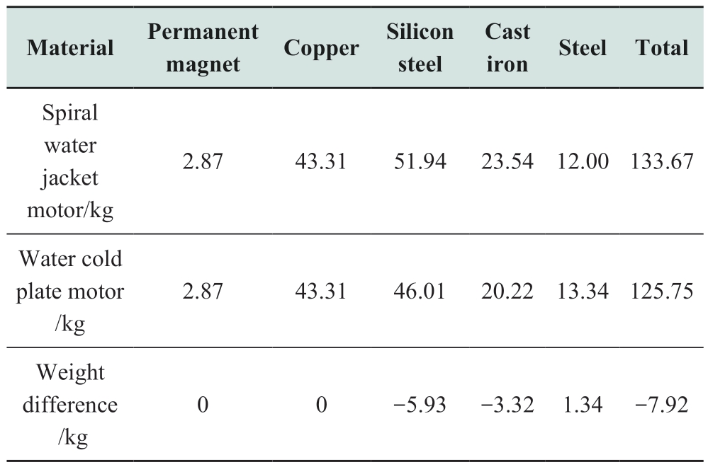
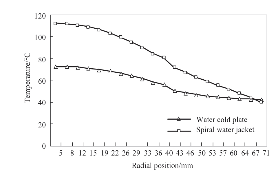
Fig.9 Comparison of radial temperature distribution of two structures
5 Design case of motor cooling system using water cold plates
The cooling system design of a high-speed motor is a vital part of the motor design.For the traditional cooling structure of an external spiral water jacket motor, the design process primarily includes the calculation of the cooling water flow and the design of the spiral water channel.When designing a cooling system for a high-speed permanent magnet synchronous motor with water cold plates, the required cooling water flow, thickness of the water cold plate, and required number of water cold plates are calculated from the motor loss density and axial length of the motor stator core.
5.1 Main parameters of the prototype
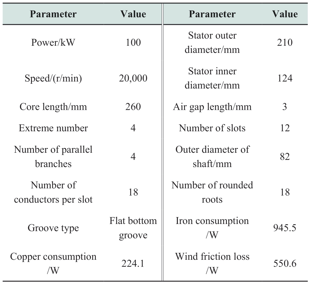
The prototype selected in this part is a high-speed permanent magnet synchronous motor with 4-poles and 12-slots.The winding was a double-layer winding, and the rotor sheath was a carbon fiber sheath.The primary parameters are listed in Table 5.
Table 5 Main parameters of the prototype
5.2 Design of motor cooling system using water cold plates
(1) Calculation of cooling water flow
When calculating the cooling water flow, it is necessary to start from the loss density or total loss of the motor and consider the temperature difference between the inlet and outlet as one of the constraints.Therefore, the cooling water flow is calculated as follows:
where ΔT is the temperature difference between the inlet and outlet, (its reasonable value should be between 5 and 10 K), ρ is the density of the cooling medium, the cooling medium in this part is water, p is the total loss of the water cold part, and c is the specific heat capacity of the cooling medium.
(2) Determination of the thickness and quantity of the water cold plate
The product of the thickness and the number of water cold plates is the total thickness of the water cold plate,which is the thickness ΔL of the replaced part of the stator core.The value of ΔL affects the cross-sectional area of the water channel, which further affects the power consumption of the pump, and the total loss of the iron core.
Increasing ΔL, reduces the flow resistance of the water channel, reduces the power consumption of the pump, and increases the total loss of the stator core.The optimal value of ΔL is obtained when the sum of the two is the smallest.
The pressure difference between the inlet and outlet of the water cold plate is calculated using Eq.(3).
where k is the loss coefficient, v is the water flow rate, S is the cross-sectional area of the inlet and outlet of the water channel, and q is the cooling water flow rate.
The energy loss of cooling water in the water cold plate is:

where n is the number of water cold plates, which is an integer greater than or equal to 1, and b is the wall thickness of the water cold plates.
Because the embedding of the water cold plates must replace an equal volume of the stator core, to maintain the original electromagnetic characteristics of the motor, its magnetic load must be increased by a certain proportion.Consequently, the main magnetic flux is increased, which increases the loss density.
When the effective iron core length is reduced, the magnetic load must increase proportionally, and the loss density increases quadratically.However, because the volume of the stator iron core is reduced in the same proportion, the total loss of the stator iron core after adding the water cold plates is:
where L is the length of the stator core.
Therefore, the sum of the kinetic energy loss of the cooling water in the water cold plates and the total loss on the iron core is:

From the relationship curve between the thickness of the water-cold plate and the effective cooling length,the optimal thickness of the water-cold plates should be between 12-15 mm.The length of the iron core is 260 mm,the wall thickness of the water cold plate is 3 mm, and the sum of the kinetic energy loss of the cooling water in the water cold plates and the total loss on the iron core had the minimum value.Further ΔL was 32.4 mm and n is 2.
Following comprehensive consideration, the cooling solution that can be obtained involved choosing two cold water plates with a thickness of 16.2 mm.
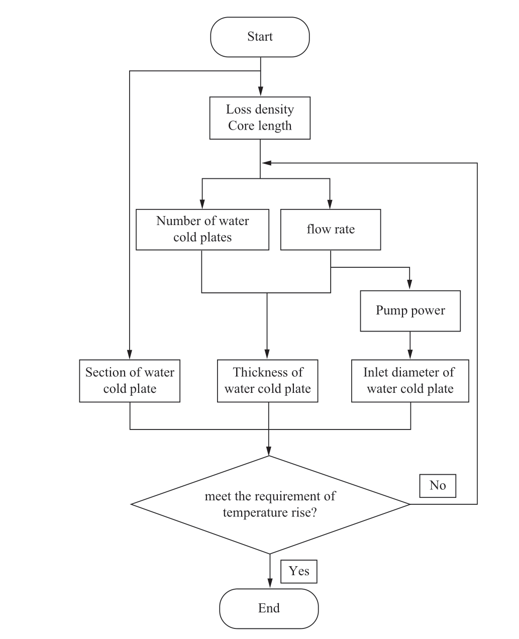
Fig.10 Flow chart of water cold plate design
The flow chart shown in Fig.10 describes the design process more clearly.
(3) 3D model of the motor cooling structure
Following the completion of the parameter calculations,according to the structural parameters of the prototype and the calculated parameters of the water-cold plate, the motor and its cooling structure model were drawn in the Solidworks software, as shown in Fig.11; the casing part is transparent.
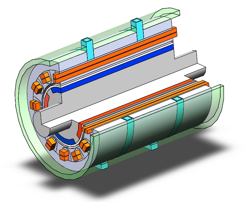
Fig.11 Model of 100 kW motor structure
5.3 Simulation verification in temperature field
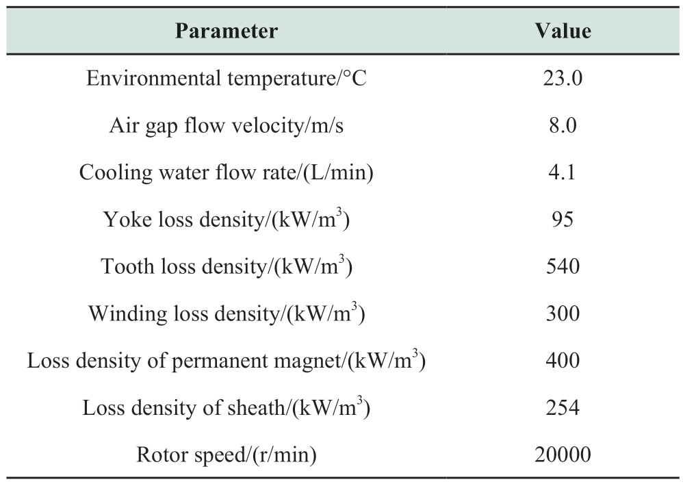
Based on the above model, a temperature field simulation was performed.The simulation conditions are listed in Table 6.
The simulation included the water and air-cooling parts of the motor cooling system.The water in the water cold plate and the airflow and heat transfer processes in the air gap are very complex.According to their structure, fluid flow, and heat transfer characteristics, certain reasonable basic assumptions must be made.
Table 6 Finite element simulation conditions
(1) The motor winding was equivalent to a conductor with a rectangular cross section, and two conductors were distributed in each slot.The insulation between the conductor and the conductor and between the conductor and the core was good.
(2) The boundary condition of the cooling medium inlet was defined as velocity-inlet, assuming that its velocity and temperature were constant.
(3) Owing to the complex structure of the winding end, an equivalent treatment was performed at the end of the winding.The connection between the windings was cancelled.The end of the winding was equivalent to an independent straight conductor.
(4) The rotor part was loaded with an average speed to simulate the rotation of the rotor.The heat source of each part of the motor was loaded with the average loss density.Air was assumed to be an ideal gas and the effect of gravity on the gas was considered during natural convection.
(5) The face of the stator and rotor, surface of the casing,and part of the shaft in contact with the air were loaded with the average convective heat transfer coefficient.The air wear on the rotor surface was directly obtained through fluid-structure coupling.
After completing the simulation, the temperature field distribution of each part was obtained via post-processing,as shown in Figs.12 and 13.
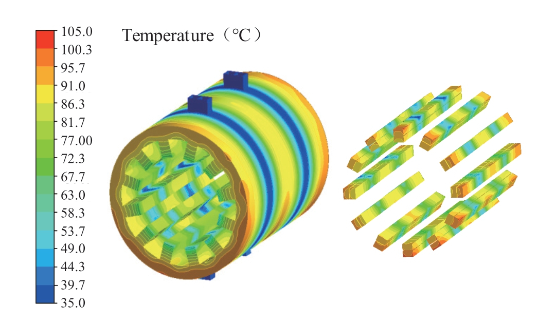
Fig.12 Temperature field of stator and winding
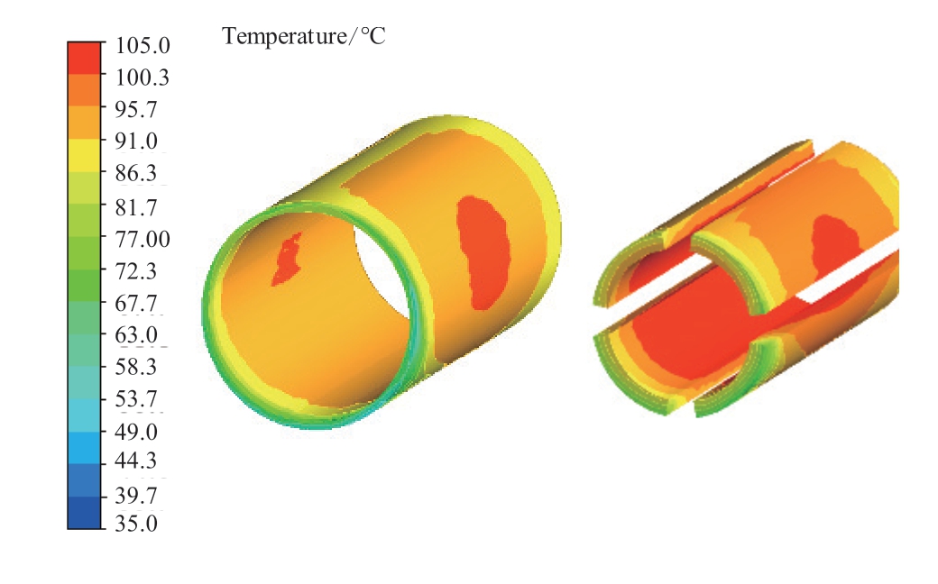
Fig.13 Temperature field of sheath and permanent magnet
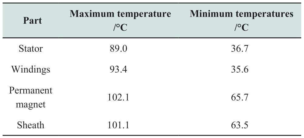
The simulation results were post-processed, and the maximum and minimum temperatures of each part were determined, as presented in Table 7.The maximum temperature of the motor appeared in the permanent magnet part, and its maximum temperature was 102.1 °C.The maximum allowable temperature of the motor insulation class E was 120.0 °C.Therefore, the designed water cold plate structure can satisfy the temperature rise requirements of the motor.
Table 7 Highest and lowest temperature of each part of the motor
6 Conclusions
To address the problems of high loss density and difficulty in dissipating the internal heat of a high-speed permanent magnet synchronous motor, a cooling structure using water-cold plates was proposed in this study.The following conclusions were drawn:
(1) The effective cooling length of the water cold plate increased with an increase in the incoming water flow,decreased with an increase in the thickness of the water cold plate, and decreased with an increase in the motor loss density.
(2) Under the condition that the total length,electromagnetic characteristics, and cooling water flow remain unchanged, compared with the outer spiral water jacket motor, the maximum and average temperatures of the motor stator with the water cold plate structure were reduced by 25.5% and 30.5%, respectively, the mass was reduced by 7.92 kg (decrease of 5.93%), and the volume was reduced by 1.92×10⁻³m3 (decrease of 10.27%).
(3) A 100 kW, 20,000 r/min high-speed permanent magnet motor was used as a prototype, and a cooling system using water-cold plates was designed.The simulation results showed that the maximum temperature of the winding was 93.4 ℃ and the maximum temperature of the permanent magnet was 102.1 ℃.This proved that the cooling structure can satisfy the temperature rise requirements of the motor.
In this study, CFD method is used to verify the effectiveness of the application of water cold plate in motor cooling system, but there are many uncontrollable factors in the actual operation of motor.In the deeper research, the design of high power density motor cooling system can also be raised to a higher level by studying these influencing factors through prototype tests and making reasonable equivalence or improvement in simulation design.With the application of high power density motor involving more and more extensive aspects and stricter requirements, it is an inevitable trend to study the hybrid cooling system of motor from the coupling of multiple physical fields.When all physical fields cannot be balanced, improvement and promotion should be made under the premise of following the principle of primary and secondary.
Acknowledgements
This work was supported by the National Natural Science Foundation of China (51920105011), Natural Science Foundation of Liaoning Province (2021-YQ-09),and Liaoning Bai Qian Wan Talents Program, China.
Declaration of Competing Interest
We declare that we have no conflicts of interest.
References
[1] Tang Y, Wan L, Hou J X (2019) Full electromagnetic transient simulation for large power systems.Global Energy Interconnection, 2(1): 29-36
[2] Wu Y Y, Wang C Y, Chen Y, et al.(2019) Influence of spacer insulator material temperature characteristics on its electric properties.Global Energy Interconnection, 2(1): 71-77
[3] Sun MC, Tang RY, Han XY, et al.(2018) Temperature field analysis of different cooling schemes for high frequency amorphous alloy axial flux permanent magnet motor(In Chinese).Journal of Motor and Control, 22(2): 1-8
[4] Fasquelle A, Laloy D (2017) Water cold plates cooling in a permanent magnet synchronous motor.IEEE Transactions on Industry Applications, 53(5): 4406-4413
[5] Huang J K, Shoai Naini S, Miller R, et al.(2019) A hybrid electric vehicle motor cooling system—Design, model, and control.IEEE Transactions on Vehicular Technology, 68(5):4467-4478
[6] Hu X, An YJ, Yang WG (2020) Analysis of cooling system of vacuum pump canned motor based on fluid-solid coupling method(In Chinese).Motor and Control Applications, 47(2): 80-85
[7] Liu G W, Liu M Y, Zhang Y, et al.(2020) High-speed permanent magnet synchronous motor iron loss calculation method considering multiphysics factors.IEEE Transactions on Industrial Electronics, 67(7): 5360-5368
[8] Wang T Y, Zhang Y, Wen F Q, et al.(2019) Coupling calculation and analysis of three-dimensional temperature and fluid field for high-power high-speed permanent magnet machine.IET Electric Power Applications, 13(6): 820-825
[9] Chen WR, Niu Z, Han Z, et al.(2019) Flow following control strategy for thermal management of water-cooled PEMFC.Chinese Journal of Solar Energy, 40(04): 942-949
[10] Guo MW, Gao J, Deng Y, et al.(2017) Study on design of cooling system for a 1.5mw wind turbine generator.Chinese Journal of Solar Energy, 38(03): 648-654
[11] Xia Y, Lv S, Jing B, et al.(2023) Improvement of Heat Dissipation Structure of Low Speed Permanent-magnet Motor.IEEE Access,1-1
[12] Wang XY, Zhou C (2016) Temperature field analysis and cooling method of disc permanent magnet synchronous motor based on PCB winding.Chinese Journal of Electrical Engineering, 36(11):3062-3069
[13] Jorge EE, José MBDL (2019) Bearing analysis for the electrofans in the water cooling system of Hyundai motors.Ingeniería Mecánica, 22(2): 85-91
[14] Satrústegui M, Martinez-Iturralde M, Ramos J C, et al.(2017)Design criteria for water cooled systems of induction machines.Applied Thermal Engineering, 114: 1018-1028
[15] Reuter S, Berg L F, Doppelbauer M (2022) Performance evaluation of a high-performance motor with thermoset molded internal cooling.2021 11th International Electric Drives Production Conference (EDPC).Erlangen, Germany.IEEE, 1-5
[16] Chang J J, Fan Y N, Wu J L, et al.(2021) A yokeless and segmented armature axial flux machine with novel cooling system for In-wheel traction applications.IEEE Transactions on Industrial Electronics, 68(5): 4131-4140
[17] Liu C, Xu Z Y, Gerada D, et al.(2020) Experimental investigation on oil spray cooling with hairpin windings.IEEE Transactions on Industrial Electronics, 67(9): 7343-7353
[18] Yamamoto S, Nishikawa A, Harada T, et al.(2022) Development of direct cooling stator structure using high thermal conductive epoxy molding compounds.2022 International Power Electronics Conference (IPEC-Himeji 2022- ECCE Asia).Himeji, Japan.IEEE, 407-414
[19] Wanjiku J, Ge L, Zhang Z Y, et al.(2021) Electromagnetic and direct-cooling analysis of a traction motor.2021 IEEE Energy Conversion Congress and Exposition (ECCE).Vancouver, BC,Canada.IEEE, 1461-1467
[20] Acquaviva A, Skoog S, Thiringer T (2021) Design and verification of In-slot oil-cooled tooth coil winding PM machine for traction application.IEEE Transactions on Industrial Electronics, 68(5): 3719-3727
[21] Fan X G, Li D W, Qu R H, et al.(2020) Water cold plates for efficient cooling: Verified on a permanent-magnet machine with concentrated winding.IEEE Transactions on Industrial Electronics, 67(7): 5325-5336
[22] Yao Z X, Mandel R K, McCluskey F P (2022) Cooling jacket for high power density segmented electric motor.2022 IEEE Transportation Electrification Conference & Expo (ITEC).Anaheim, CA, USA.IEEE, 1082-1086
[23] Yu Z Y, Li Y, Jing Y T, et al.(2022) Cooling system of outer rotor SPMSM for a two-seater all-electric aircraft based on heat pipe technology.IEEE Transactions on Transportation Electrification, 8(2): 1656-1664
[24] Berndl S, Kleimaier A (2021) Encapsulated air cooling system for scalable axial flux motors.2021 International Conference on Electrical Drives & Power Electronics (EDPE).Dubrovnik,Croatia.IEEE, 43-49
[25] Haller S, Persson J, Cheng P, et al.(2020) Multi-phase winding with In-conductor direct cooling capability for a 48V traction drive design.2020 International Conference on Electrical Machines (ICEM).Gothenburg, Sweden.IEEE, 2118-2124
[26] Zhang Y Q, Geng W W, Li Q (2022) Thermal design of aircooled YASA AFPM motor with heat pipes.2022 IEEE Transportation Electrification Conference and Expo, Asia-Pacific(ITEC Asia-Pacific).Haining, China.IEEE, 1-6
[27] Li Q, Shen X, Mecrow B, et al.(2021) Hybrid cooling design of permanent magnet synchronous machines.The 10th International Conference on Power Electronics, Machines and Drives (PEMD 2020)., Online Conference.Institution of Engineering and Technology, 395-400
[28] Zhang F Y, Gerada D, Xu Z Y, et al.(2022) Improved thermal modeling and experimental validation of oil-flooded highperformance machines with slot-channel cooling.IEEE Transactions on Transportation Electrification, 8(1): 312-324
[29] Wu S N, Hao D Q, Tong W M (2022) Cooling system design and thermal analysis of modular stator hybrid excitation synchronous motor.CES Transactions on Electrical Machines and Systems,6(3): 241-251
[30] Smith R, Tikadar A, Kumar S, et al.(2022) Evaporative cooling of high power density motors: Design and analysis.2022 21st IEEE Intersociety Conference on Thermal and Thermomechanical Phenomena in Electronic Systems (iTherm).San Diego, CA,USA.IEEE, 1-8
[31] Zhao H (2023) Effectiveness of Thermal Interface Materials on Electrical Machines Thermal Performance with Heat Pipes.IEEE Transactions on Transportation Electrification, 1-1
Received: 22 October 2022/ Accepted: 28 February 2023/ Published: 25 June 2023
Guangwei Liu
liu-gw@outlook.com
Xin Zhao
moonlight6363@qq.com
Haojie Cui
harris.cui@pan-good.com
Yun Teng
tengyun@sut.edu.cn
Zhe Chen
zch@et.aau.dk
f frequency (Hz)
β frequency index
Bm magnetic induction intensity (T)
ΔL total thickness of water cold plate (m)
q water flow (L/min)
p loss of the water cold plate (W)
c specific heat capacity (J/kg/℃)
ρ density (kg/m3)
ΔT temperature difference (℃)
k loss coefficient
v water flow rate (m/s)
S cross-sectional area (m2)
2096-5117/© 2023 Global Energy Interconnection Development and Cooperation Organization.Production and hosting by Elsevier B.V.on behalf of KeAi Communications Co., Ltd.This is an open access article under the CC BY-NC-ND license (http: //creativecommons.org/licenses/by-nc-nd/4.0/ ).
Biographies

Xin Zhao received her master’s degree in control theory and control Engineering from Shenyang University of Technology,Shenyang, China, in 2008.She joined the Shenyang University of Technology in 2008,where she is currently a researcher in electrical engineering.Her research interests include Special motor and its control system.

Haojie Cui received his master’s degree from Shenyang University of Technology,Shenyang, China, in 2021.Now, he is working as an engineer in Zhejiang PanGood Power Technology Co., Ltd.Jinhua, China.His research interests include the design of motor cooling system and axial flux motor.

Yun Teng received his doctor’s degree in electrical engineering from Shenyang University of Technology, Shenyang, China,in 2009.He joined the Shenyang University of Technology in 2010, where he is currently a professor in electrical engineering.He is a standing director as the IEEE PES DC Distribution Network Technical Subcommittee.His research interests include multi-energy system dispatching automation and smart grid control theory.

Zhe Chen received his B.Eng.and M.Sc.degrees from Northeast China Institute of Electric Power Engineering, Jilin City, China,and his Ph.D.degree from the University of Durham, Durham, U.K.He is a full professor with the Department of Energy Technology,Aalborg University, Aalborg, Denmark, where he is the leader of the Wind Power System Research program in the Department of Energy Technology.He is also the Danish Principle Investigator for Wind Energy of the Sino-Danish Centre for Education and Research.His research areas are power systems, power electronics and electric machines; and his main current research interests are wind energy and modern power systems.

Guangwei Liu received his B.Eng., M.Sc.and Ph.D.degrees in electrical engineering from Shenyang University of Technology,Shenyang, China, in 2005, 2008 and 2015 separately.He joined the Shenyang University of Technology in 2008, where he is currently a full professor in school of electrical engineering.His major research interests and activities are in the areas of permanent magnet electrical machines and its drive.
(Editor Dawei Wang)
