0 Introduction
Owing to the large-scale development of renewable energy,the multi-inverter grid-connected system has become a standard power generation structure,especially in new energy station,but grid conditions and complex interactions between inverters pose significant challenges to stable operation [1,2].Electromagnetic transient (EMT)simulation is one of the preferred tools for analyzing and verifying the dynamics of such a typical inverterdominated system.However,the inherent contradiction between simulation efficiency and accuracy is significant,especially when the switching frequency and number of grid-connected inverters increase,such that it is difficult to accept the time cost of EMT simulation [3,4].
In addition to using high-performance computing hardware [5],improving the simulation model and numerical algorithm is the most effective method for enhancing simulation speed.These two methods are mostly based on the expansion of time scale,where the averaging model is widely used,including state-space averaging method [6-8],circuit averaging method [9,10],and dynamic phasor (DP) method [11-13].DP is derived using a Fourier transform and reasonable Fourier coefficients,allowing the original state of instantaneous value to be modeled by a time-invariant phasor [14].Because the switching process in the time domain is replaced,the accuracy of the dynamic phasor model is between that of the detailed model and the ordinary average model,which has been gradually applied to the direct current (DC) distribution system,microgrid [15,16]and other scenarios [17].
However,when only the DP model is used in simulations,it is often difficult to achieve the desired level of accuracy,especially for the inverter-dominated system [18].To solve this problem,a hybrid simulation scheme that uses DP to model non-critical parts of the power system,and selects EMT to model critical parts is developed.By simulating at different time scales,a tradeoff between efficiency and accuracy can be finally achieved.In [19],the shifted-frequency phasor,DP and EMT were combined to form a transient simulation for hybrid line commutated converter-modular multi-level converter(LCC-MMC) grids,where LCCs are represented by DPs and most alternating current (AC) grids are covered in the EMT subsystem.The interface model between DP and EMT subsystems is modeled as a special controlled voltage and current circuit,but the errors caused by the interface are not fully considered.In [20],a DP-based interface model is introduced into EMT and transient stability hybrid simulations,thus improving interface errors caused by waveform distortion and time delay,but the scheme of hybrid simulation is too complex,making it only applicable to parallel simulation.In [21] and [22],the DP-EMT hybrid simulation is further applied to the multi-terminal DC distribution system,and the error mechanism is analyzed.However,the interface is located at the DC side,which is not applicable to the multi-inverter grid-connected system owing to the single- or three-phase topologies and control strategies.
To realize an efficient transient simulation of a multiinverter grid-connected system,the framework of hybrid simulation is adopted here,and the main works are as follows.
1) The DP model of single-phase and three-phase inverters are established first by the framework of hybrid simulation.
2) An interface scheme is designed considering the numerical compatibility problem between DP and instantaneous value,and then differences in the efficiency and accuracy of several extraction algorithms are compared in detail.
3) A DP-EMT hybrid simulation method is developed,as well as a platform of a multi-inverter grid-connected system built on MATLAB/Simulink,and then the performance of the hybrid simulation is evaluated via comparison with the EMT simulation.
The remainder of this paper is organized as follows.Section 1 introduces the basic concepts and properties of DP.Section 2 presents the DP-based modeling process of the single-phase and three-phase inverters.The interface,hybrid simulation method,and platform on MATLAB/Simulink are designed in Section 3.The case studies are discussed in Section 4,followed by Section 5,which concludes the paper.
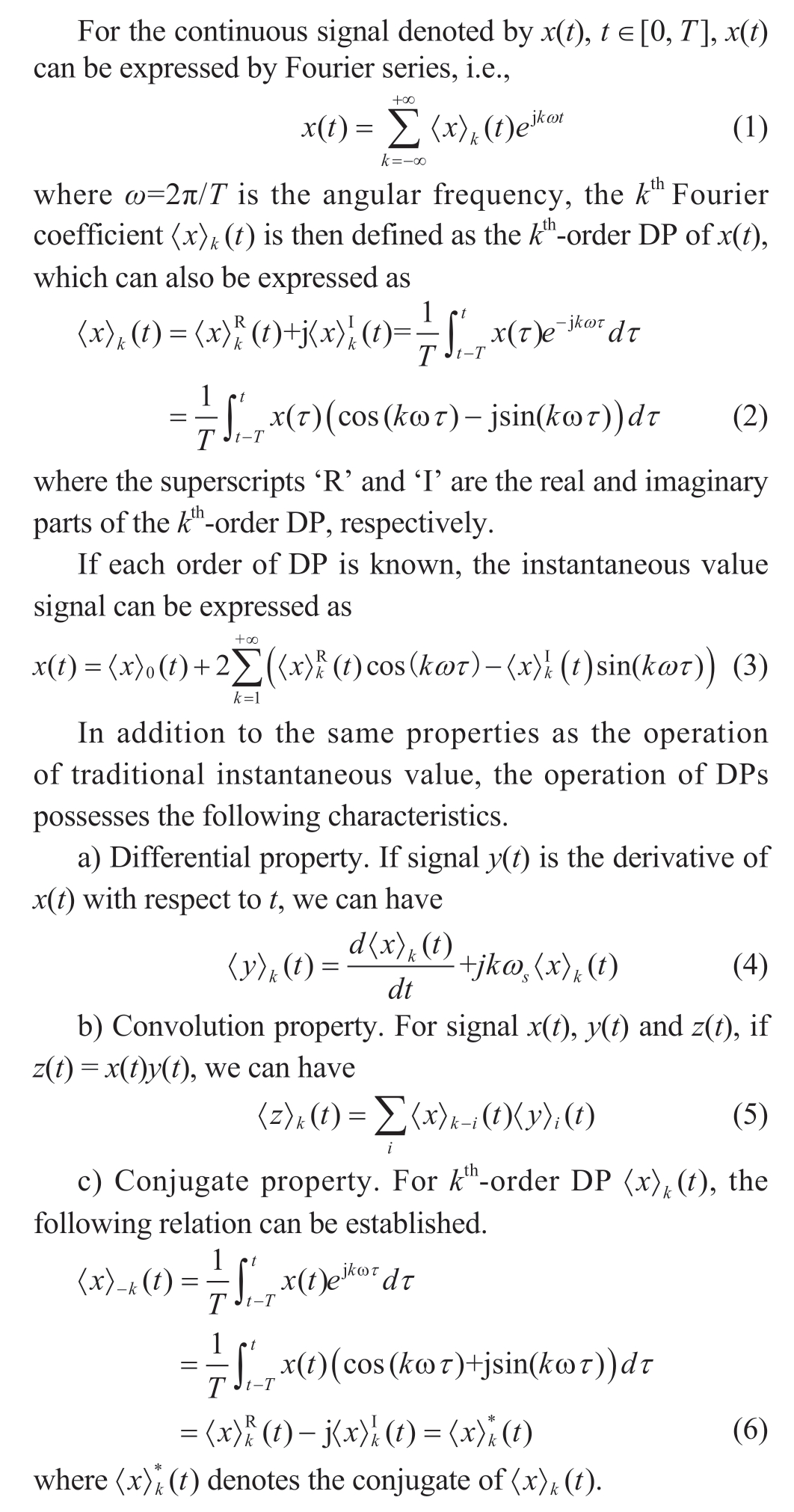
1 Basic concepts and properties of DP
2 DP-based Companion Circuit of Inverter
2.1 DP-Modeling of Single-Phase Inverter
According to the number of output phases,inverters can be categorized as single-phase inverters,three-phase inverters,and multi-phase inverters,and the former two are widely used in renewable energy generation.Taking the single-phase inverter shown in Fig.1 for example,its DP modeling process is as follows.
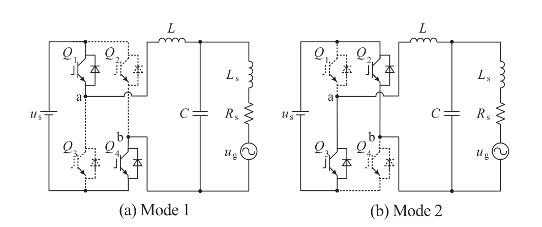
Fig.1 Circuit and its switching mode of single-phase grid-connected inverter


2.2 DP Modeling of Three-phase Inverter
Similar to the single-phase inverter,the upper and lower switching devices of each leg in the three-phase inverter shown in Fig.2(a) are not switched on simultaneously.The switching function of each leg (sp) can be expressed as

Fig.2 Circuit of three-phase grid-connected inverter
where p ∈ { a,b,c} represents three phases.
After introducing the switching function to express the switching process of three-phase inverter,the dynamics of the three-phase inverter can be expressed as
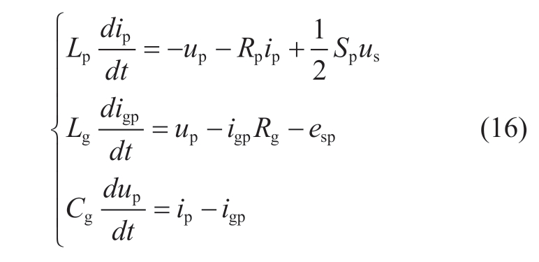
where Lp,Rp, Cg,esp,ip,isp,Lg,and Rg denote the equivalent inductance at AC side of bridge,resistance at AC side of bridge,filter capacitance,grid voltage of each phase,ACside current of each phase,grid current of each phase,equivalent inductance of unity grid,resistance of unity grid,respectively,and the switching function Sp =(2sp− 1).
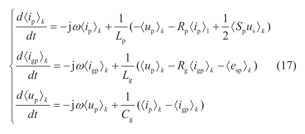
Similar to the modeling of single-phase inverter,(16)can be expressed by the kth-order dynamic phasor,thus forming the DP model shown in (17).The equivalent circuit is shown in Fig.2(b).
3 Design and implementation of hybrid simulation
As previously stated,there are significant differences in physical characterization,time scale and model composition between DP and EMT modeling.When they are applied together to the transient simulation of a multi-inverter grid-connected system,a reasonable interface mechanism becomes the indispensable link.
3.1 Interface Design in Hybrid Simulation
When the concerned inverter adopts the detailed EMT modeling (which is denoted by EMT subsystem for short),and the unconcerned inverter adopts DP modeling (which is denoted by DP subsystem for short),the DP subsystem can be expressed as a Thevenin equivalent circuit in terms of external characteristics.Therefore,the controlled voltage source can be uniformly used as the interface circuit for the single-step solution of the DP subsystem,and the interactive variable is the amplitude of the controlled source.
The interface scheme design for hybrid simulation is shown in Fig.3.The single-phase interaction is used in the single-phase inverter grid,while the three-phase system uses the three-phase variables.Under the premise of three-phase symmetry,two methods can be considered for reducing the number of interfaces and improve improving simulation efficiency.One is to extract the voltage and current of one phase and obtain the parameters of the other two phases after rotating 120 degrees.The other is to extract the voltage and current of two phases,and then superimpose them to obtain the third phase parameters.The main functions of the interface are as follows.
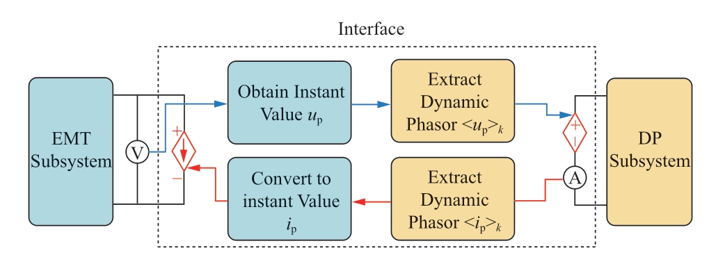
Fig.3 Interface mechanism in hybrid simulation
a) Instantaneous value generation of interactive variable
The interactive variable from the DP subsystem needs to correspond to the order of the dynamic phasor model.During the execution period of the interaction interval,the instantaneous value is sampled by the EMT simulation step∆t,and then the instantaneous value sequence required by the EMT subsystem is obtained.
b) Dynamic phasor extraction of an interactive variable.
To make the subsystems on both sides interact continuously,the DP subsystem’s simulation step length∆T can be the same as the interaction interval and is n times the ∆t,where n is an integer.There are two types of algorithms to extract dynamic phasor value of interactive variable from the data sequence of instantaneous value.One is to calculate by the definition,and the other is by waveform fitting.Although the definition calculation has the advantage of being highly efficient,its disadvantage is that the representation of the sequence has an inherent time delay.Conversely,the waveform fitting method has an advantage in accuracy which reduces the efficiency of simulation.The commonly used waveform fitting algorithms include the least-square algorithm,fast Fourier decomposition algorithm,and maximum likelihood estimation algorithm.These algorithms have different advantages and disadvantages.Taking the discrete data sequence shown in (18) as an example,this paper obtains the comparison results of the algorithms shown in Table 1 by analyzing the three aspects of computational efficiency;extraction accuracy and anti-noise performance.
Table 1 Comparison of extraction methods for dynamic phasor
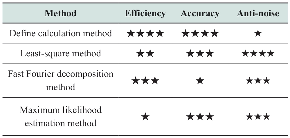

The noise part in (19) consists of the white noise and the 5th- and 7th-harmonics.The signal-to-noise ratio of white noise is 15 dB.The sampling interval and length of data window are 10 μs and 20 ms,respectively.
3.2 Main Process of Hybrid Simulation
For the hybrid simulation of grid-connected systems based on multiple inverters,the low-voltage and highvoltage bus can both be chosen as its interface position.Taking the low-voltage bus as an example,the division of the DP EMT subsystems is shown in Fig 4,where Inverters D and E constitute the EMT subsystem while the remaining inverters constitute the DP subsystem.

Fig.4 Subsystem division of multiple inverters gridconnected system in hybrid simulation
Due to the existence of an interface between the EMT and DP subsystems,there is no strict correspondence required for solving this sequence,thus generating serial and parallel simulations.When the hybrid simulation is implemented on the existing EMT simulation platform,serial simulation can be applied in the offline simulation platform while parallel simulation is more applicable to realtime simulation platforms.The selection of specific schemes needs to consider the limitation of simulation platforms on embedded modules.Taking the realization of serial hybrid simulation based on MATLAB/Simulink as an example,the DP subsystem and interface module can be compiled by custom components.The specific implementation process is shown in Fig.5.

Fig.5 Main process of the hybrid simulation algorithm
4 Case studies
The isomorphism hybrid simulation platform based on MATLAB/Simulink is developed to demonstrate the performance of the DP-EMT hybrid simulation method,and it is implemented on an Intel Core i7-9700 3.20 GHz machine with 16 GB RAM.If no time steps are specified,the EMT and DP subsystems default to 1 s and 100 s,respectively.
4.1 Hybrid simulation of single-phase multiinverter system
Five single-phase inverters,lines,and unity grid,are involved,and the topology is like that of Fig.4.The three inverters constitute the DP subsystem and the remaining part of the system constitute the EMT subsystem.To verify the accuracy of the DP-based hybrid simulation,openloop testing is adopted first.Fig.6 demonstrates the ACside voltage of single-phase inverter connected to strong grid.Trajectories of hybrid simulation and EMT simulation stay highly consistent.In Fig.7,the strong grid is changed into weak grid,DC voltage us steps from 800 V to 600 V at t = 0.5 s,and the AC-side voltage of single-phase inverter is shown.The DP-based hybrid simulation maintains high accuracy in both steady and transient states.

Fig.6 AC-side voltage of single-phase inverter connected to strong grid
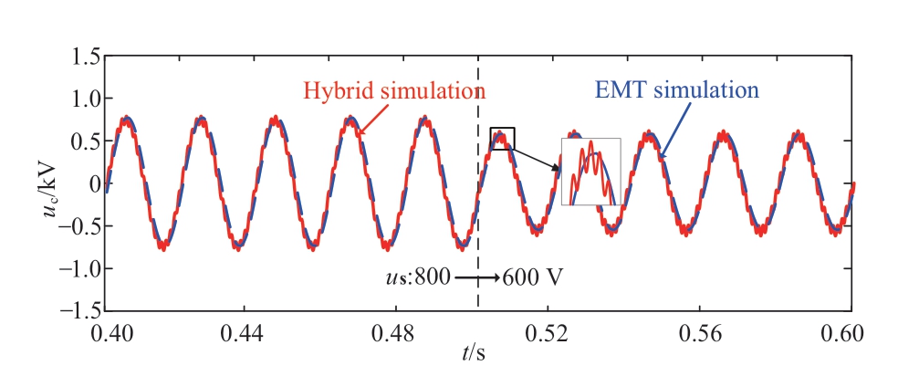
Fig.7 AC-side voltage of single-phase inverter connected to weak grid
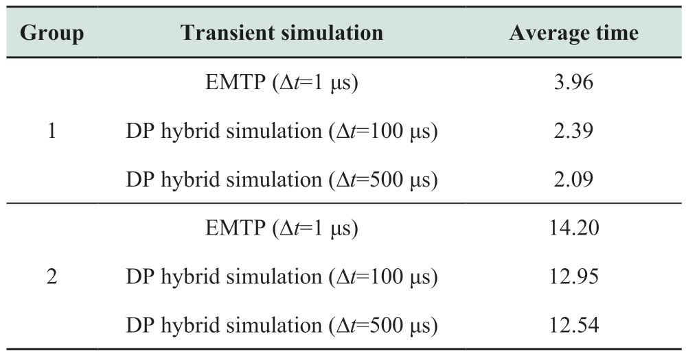
The average time costs of 50 simulations using DPbased hybrid simulation and EMT simulation are given in Table 2,where the 1st and 2nd groups of experiments have 1 inverter and 5 inverters,respectively,whereas the corresponding hybrid simulations have 1 interface and 3 interfaces,respectively.In the 1st group,when compared to EMT simulations,the average time cost of DP-based hybrid simulation is reduced by 39.65% and 47.22% respectively,with an increase in time step for an inverter circuit.In the 2nd group,owing to an increase in the interface number,the efficiency of DP-based hybrid simulation is reduced.
Table 2 Average time cost of transient simulation
4.2 Hybrid simulation of three-phase multiinverter system
A three-phase five-inverter grid-connected system with power control is adopted to further illustrate the performance of DP-EMT hybrid simulation,as shown in Fig.4.The steady operating points of each three-phase inverter are all set to Pref =5 kW,and Qref = 0 kW.
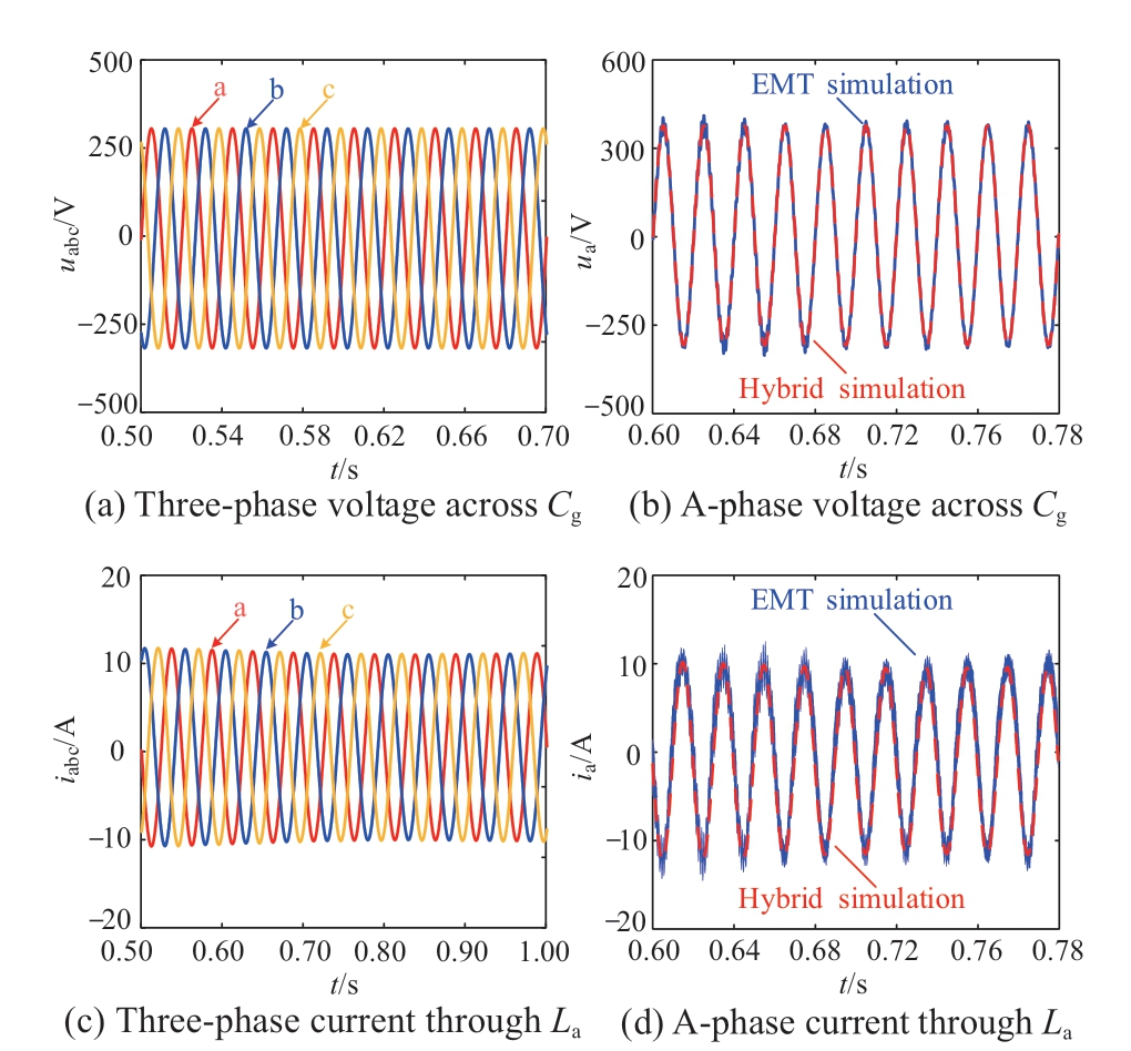
Fig.8 AC-side voltage and current of three-phase inverter
Figs.13 and 14 present the AC-side voltage and current of DP-based hybrid simulation for the three-phase inverter.At t = 1.0 s,the steady operating point of Inverter A is changed.Compared with the EMT simulation,hybrid simulation can quickly reflect the characteristics of multiterminal system and maintains high accuracy.

Fig.9 A-phase voltage and current of three-phase inverter
5 Conclusions
Here,a DP-EMT hybrid simulation method is proposed for multi-inverter grid-connected power systems,and a hybrid simulation platform based on MATLAB/Simulink is implemented.Via comparison with the full EMT simulation,the effectiveness of the hybrid simulation method was demonstrated.The hybrid simulation makes full use of the existing EMT platform,and the accuracy and high efficiency of multiple inverter grid-connected system can be guaranteed.
Acknowledgements
This work was supported by the State Grid Science and Technology Project (grant no.KJ2021-069).
Declaration of Competing Interest
We declare that we have no conflict of interest.
References
[1] Yu C,Xu H,Liu C,et al.(2021) Stability margin analysis of multi-inverter grid-connected system considering asynchronous control period under high penetration.Proceedings of the 2021 IEEE Energy Conversion Congress & Exposition-Asia,pp 2080-2085
[2] Mohamad A M I,Mohamed Y A R I (2018) Investigation and enhancement of stability in grid-connected active DC distribution systems with high penetration level of dynamic loads.IEEE Transactions on Power Electronics,34(9): 9170-9190
[3] Peng H,Mo W,Luan L,et al.(2020) Simulation of Distribution Network Using Shifted-Frequency Electromagnetic Transient Program.Proceedings of the 2020 IEEE International Conference on Power and Energy Systems,pp 114-118
[4] De Carne G,Lauss G,Syed M H,et al.(2022) On modeling depths of power electronic circuits for real-time simulation–a comparative analysis for power systems.IEEE Open Access Journal of Power and Energy,9: 76-87
[5] Guo J,Li Y,Zhu H,et al.(2019) Research on Performance Improvement of Power Simulation Software by Cloud Platform.Proceedings of the 2019 IEEE Sustainable Power and Energy Conference,pp 2927-2930
[6] Han Y,Sun H,Huang B,et al.(2021) Discrete-time state-space construction method for SSO analysis of renewable power generation integrated AC/DC hybrid system.IEEE Transactions on Power Systems,37(3): 2322-2334
[7] Azer P,Emadi A (2020) Generalized state space average model for multi-phase interleaved buck,boost and buck-boost DC-DC converters: Transient,steady-state and switching dynamics.IEEE Access,8: 77735-77745
[8] Kwon B K,Han S,Kwon W H (2007) Minimum variance FIR smoothers for continuous-time state space signal models.IEEE Signal Processing Letters,14(12): 1024-1027
[9] Akbarabadi S A,Atighechi H,Jatskevich J (2013) Circuitaveraged and state-space-averaged-value modeling of secondorder flyback converter in CCM and DCM including conduction losses.Proceedings of the 2013 IEEE International Conference on Power Engineering,Energy and Electrical Drives,pp 995-1000
[10] Sanders S R,Verghese G C (1990) Synthesis of averaged circuit models for switched power converters.IEEE international Symposium on Circuits and Systems.IEEE,679-683
[11] Wang Q,Ye H,Zhang G (2017) Improved dynamic phasorbased modeling and simulation of modular multilevel converter.Proceedings of the 2017 IEEE Conference on Energy Internet and Energy System Integration,pp 1-6
[12] Chen P W,Liu Y Z,Ruan X B,et al.(2023) Dynamic simulation method of virtual synchronized power grid based on Haar wavelet collocation methld.Proceedings of the CSEE,1-12
[13] Vejdan S,Sanaye-Pasand M,Malik O P (2015) Accurate dynamic phasor estimation based on the signal model under offnominal frequency and oscillations.IEEE Transactions on Smart Grid,8(2): 708-719
[14] Chen P W,Liu Y Z,Ruan X B,et al.(2020) Stochastic Electromagnetic Transient Simulation Algorithm Applied to Power Electronics Dominated Power System.Proceedings of the Chinese Society of Electrical Engineering 41(11): 3829-3840
[15] Chavan R (2017) Dynamic phasor based modelling of hybrid FCPV module for microgrid application.Proceedings of the 2017 IEEE North American Power Symposium,pp 1-6
[16] Shuai Z,Peng Y,Guerrero J M,et al.(2018) Transient response analysis of inverter-based microgrids under unbalanced conditions using a dynamic phasor model.IEEE Transactions on Industrial Electronics,66(4): 2868-2879
[17] Venkatramanan D,John V (2017) Modeling and analysis of passive networks using dynamic phasors for study of islanded inverters.Proceedings of the 2017 IEEE Transportation Electrification Conference,pp 1-6
[18] Guo X,Lu Z,Wang B,et al.(2014) Dynamic phasors-based modeling and stability analysis of droop-controlled inverters for microgrid applications.IEEE Transactions on Smart Grid,5(6):2980-2987
[19] Shu D,Wei Y,Dinavahi V,et al.(2019) Cosimulation of shiftedfrequency/dynamic phasor and electromagnetic transient models of hybrid LCC-MMC DC grids on integrated CPU–GPUs.IEEE Transactions on Industrial Electronics,67(8): 6517-6530
[20] Shu D,Xie X,Dinavahi V,et al.(2017) Dynamic phasor based interface model for EMT and transient stability hybrid simulations.IEEE Transactions on Power Systems,33(4): 3930-3939
[21] Chen P W,Lu L,Liu N,et al.(2023) Dynamic phasorelectromagnetic transient hybrid simulation and error mechanism analysis of DC distribution system.Proceedings of the CSEE,43(06): 2283-2295
[22] Lu L,Chen P,Liu N (2022) Stochastic Transient Simulation Method Based on Dynamic Phasor.Proceedings of the 2022 IEEE/IAS Industrial and Commercial Power System Asia,pp 2101- 2106
Full-length article
Received: 28 October 2022/ Accepted: 8 January 2023/ Published: 25 April 2023
 Yunfei Xu
xyfly0528@hotmail.com
Peng Yang
candela_yp@163.com
Qian Li
527874527@qq.com
Junyu Zhao
zjy809@yeah.net
Juanjuan Lu
1209949079@qq.com
2096-5117/© 2023 Global Energy Interconnection Development and Cooperation Organization.Production and hosting by Elsevier B.V.on behalf of KeAi Communications Co.,Ltd.This is an open access article under the CC BY-NC-ND license (http: //creativecommons.org/licenses/by-nc-nd/4.0/).
Biographies

Peng Yang received the B.S.degree in power system and automation from Shanghai Jiaotong University,Shanghai,China,in 1998.He is currently working in State Grid Hebei Electric Power Co.,Ltd..His research interests mainly include power grid planning and power electronics technology.
Qian Li received the B.S.degree in power system and automation from Shijiazhuang Railway University,Shijiazhuang,China,in 2011,and a M.S.degree in power electronics and power transmission from Shijiazhuang Railway University Shijiazhuang,China,in 2015.She is currently working at State Grid Hebei Electric Power Co.,Ltd..Her research interests mainly include flexible AC/DC power grid and power electronics technology.

Junyu Zhao received the B.S.and M.S.degrees from North China Electric Power University,Beijing,China,in 2012 and 2017.He is currently working at State Grid Baoding Power Supply Company.His research interests mainly include electrical engineering and automation,electronics and communication engineering.

Juanjuan Lu received the B.S.and M.S.degrees from North China Electric Power University,Beijing,China,in 2017 and 2020.She is currently working at State Grid Smart Grid Research Institute Co.,Ltd..Her research interests mainly include IGBT series technology and power electronics.

Yunfei Xu received the B.S.degree from Chongqing University,Chongqing,China,in 2013,and a Ph.D.degree from North China Electric Power University,Beijing,China,in 2017.He is currently working at State Grid Smart Grid Research Institute Co.,Ltd..His research interests mainly include lowfrequency transmission,flexible substation,and IGBT series technology.
(Editor Tongming Liu)
