0 Introduction
Compared with traditional electromagnetic synchronous motors,wind turbines constituting permanent magnet generators have the advantages of being of small size and low weight and exhibiting low loss and high efficiency owing to the use of rare earth materials with high magnetic energy product.Thus,such permanent magnets have been widely applied in many fields.The performance of a permanent magnet generator,which is the core driving component of a wind power system,influences the operation mode of its respective unit and the stable operation of the entire wind turbine[1].
The conditions for wind turbine operation in the modern industrial field are complex,and hence,fault phenomena are common.Faults can be classified into two categories:mechanical and electromagnetic.Mechanical faults are mainly based on the eccentric phenomenon,which can occur if a wind turbine operates in an excessively hot environment,resulting in bearing deformation,air gap flux imbalance due to uneven distribution of the air gap between the rotor and the stator,formation of unilateral magnetic tension and harmonic torque,abnormal vibration and noise,and severe friction between the rotor phase,which can generate a large current and burn the motor.Electromagnetic faults include coil insulation layer damage,which results in short-circuit faults between turns,causing three-phase stator current imbalance and uneven distribution of the induced magnetic field.In a severe case,the motor can rapidly heat and burn.When the temperature is substantially high,the armature winding produces a reverse magnetic field and permanent magnet material failure,whereas other factors lead to demagnetization.Therefore,online monitoring for early detection of eccentricity,shortcircuit,and demagnetization faults in the permanent magnet generators of wind turbines is crucial for the stability and safety of wind turbine operation.
At present,scholars worldwide are conducting extensive research on motor fault problems.A hybrid approach was established to detect rotor bar damage and rotor mixed eccentricity faults in three-phase squirrel cage induction motors based on a single-phase stator current signal[2].A non-complex,time domain analysis method was proposed to consider the voltage induced in an airgap flux sensor for reliable prediction and identification of insulation failures in the rotor field winding turn and rotor dynamic eccentricity[3].Moreover,a mathematical model based on the winding function method was established[4].In reference[5-7],characteristic harmonics were extracted from the spectra of the stator current and vibration signals to determine the characteristics of motor rotor faults.In reference[8],the spectrum features of the stator current and vibration signals were fused as the basis for judging the interturn short-circuit fault.In addition,the improved wavelet packet transform algorithm and fast Fourier transform were combined to accurately detect the interturn short-circuit fault of the motor through the fault characteristic frequencies of the current and vibration signals.These studies were focused on the determination of motor faults by using various fault diagnosis methods;the most commonly employed method is a non-complex,time domain analysis method,followed by fault diagnosis from fusion of information features,vibration signal spectral analysis,and finally,magnetic analysis and diagnosis.
In this study,the stator current and induced electromotive force spectra are predominantly considered.Accordingly,a method combining wavelet packet analysis with the decomposition of abnormal nodes is proposed to reconstruct frequency segments;it can extract abnormal characteristic frequencies effectively and accurately.Based on the theory and finite element simulation results for the stator current and induced electromotive force under different fault degrees,the harmonic content is found to vary significantly with the aggravation of the fault degree;this has a certain value for early fault warning in practical engineering applications.
1 Motor parameters and finite element model
Permanent magnet direct drive fans have significant technical advantages over traditional fans.The predominant feature is that the wind wheel is directly connected to the generator rotor.Compared with doubly fed motors,permanent magnet direct drive fans can better adapt to low wind speed,with less energy consumption and lower follow-up maintenance cost.Thus,the application of permanent magnet direct drive fans is of greater importance.Three areas with low wind speed account for approximately 50% of the wind energy resources in China;hence,the use of wind turbines having permanent magnet direct drive fans is more suitable.Between 2015 and 2020,the global consumption of high-performance NdFeB permanent magnet materials for wind turbines increased from approximately 7,170 t to ~12,880 t,representing a compound annual growth rate of ~12.4%.The global consumption of high-performance NdFeB,permanent magnet materials for wind turbines,is expected to reach approximately 19,620 tons in 2025,with a compound annual growth rate of ~8.8%[9].Permanent magnet direct drive fans have gradually become the mainstream choice for wind turbines with a capacity of 3 MW or more.Furthermore,adopting gearless direct drive technology can reduce the number of wind turbine set parts,avoid the regular replacement of gearbox oil,and reduce the operation and maintenance costs.In general,the focus on the development of permanent magnet direct drive fans for wind turbines will increase in China in the future.
The generator is the core component of a wind turbine as it is responsible for converting the rotating mechanical energy into electricity and powering the electrical system.However,the generator can easily break down if it operates under variable working conditions and electromagnetic environments for a long time.Fig.1 depicts the common fault modes,including electrical,sensor,blade,control system,gearbox,yaw system,and generator faults[10].According to the fault probabilities during the actual operation of a fan,the three typical faults of permanent magnet generators in wind turbines were selected for systematic study.
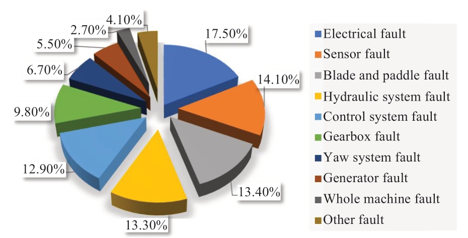
Fig.1 Wind turbine set fault ratios
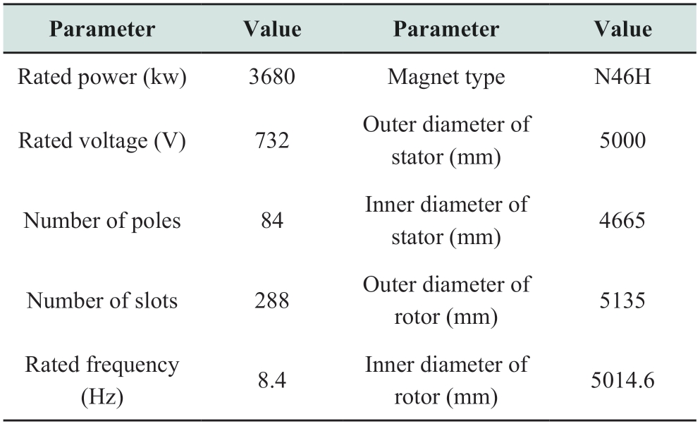
For the fault analysis of a permanent magnet generator for use in a wind turbine,an actual model of a 3680 kW motor was considered to simulate and determine the most consistent data for fault monitoring due to the complexity of the structure and the lack of a corresponding prototype test.The electromagnetic characteristics of the 3680 kW permanent magnet generator were investigated under ideal working conditions.Based on the finite element method,parametric modelling was conducted by using Ansoft Maxwell,as shown in Fig.2.Further,and Table 1 lists the motor parameters.
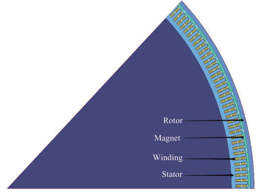
Fig.2 Model of 288-slot 84-pole 1/8 fan generator
Table 1 Motor parameters
2 Establishment of typical fault models
2.1 Rotor eccentricity simulation model
When the motor runs for a long time,with high strength and high load,the bearing will become extremely hot,resulting in bearing deformation and uneven distribution of the air gap between the rotor and the stator.Therefore,this eccentric fault was modeled and comprehensively examined.Fig.3(a)presents a schematic diagram of the motor in a normal state.The dynamic eccentricity in ANSYS was set,and under the normal state of the generator,the rotor and permanent magnet of the model have shifted a certain distance along the X-axis of the motor;the rotating axis and stator were maintained,as shown in Fig.3(b).In the case of static eccentricity,an additional local coordinate system should be set,as depicted in Fig.3(c).To study the change in the electromagnetic characteristics of the permanent magnet generator with different degrees of rotor eccentricity,the eccentricity of multiple rotors was increased to realize fault[11-13].
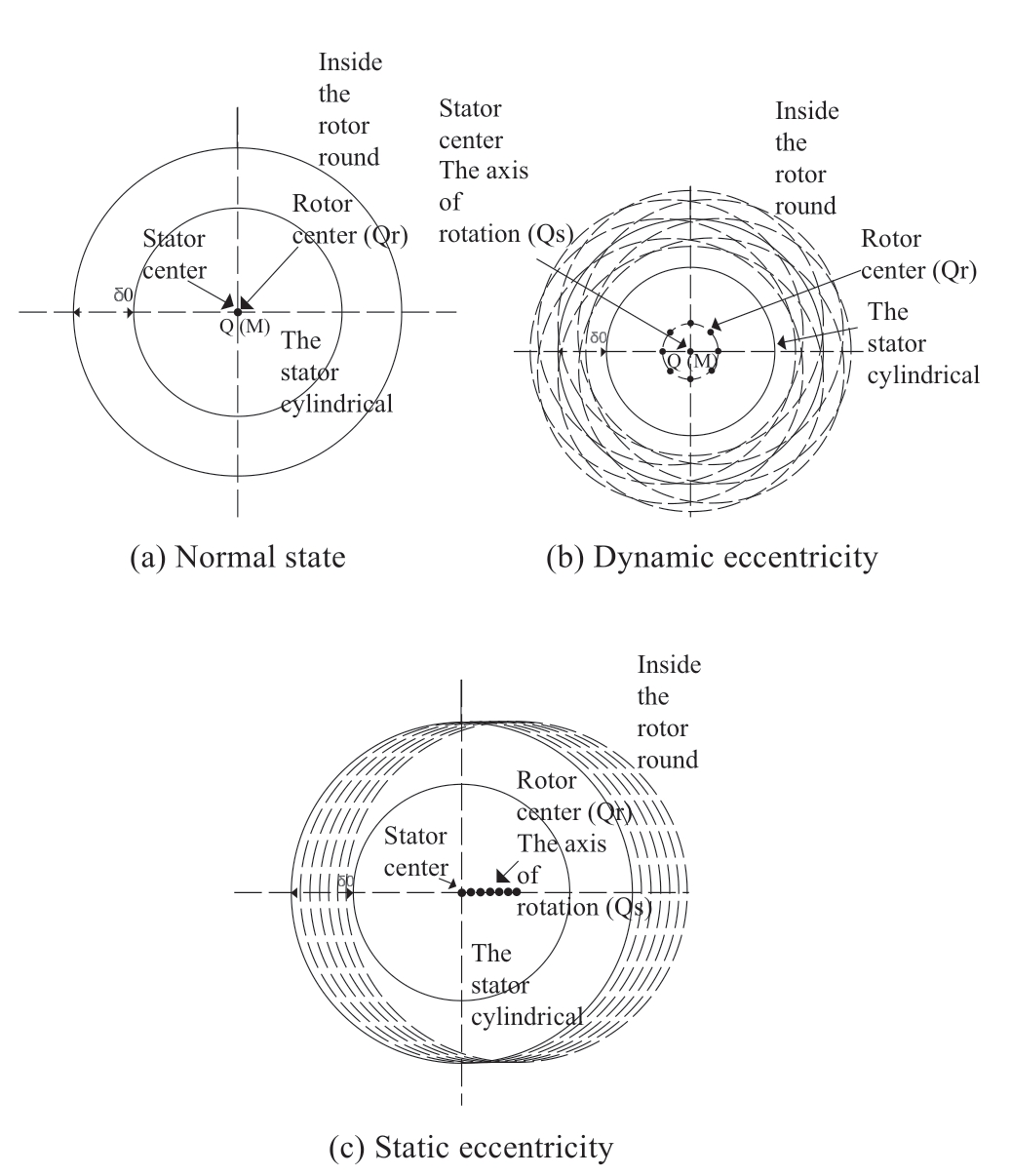
Fig.3 Structure of permanent magnet generator
2.2 Short-circuit fault simulation model
In the case of long-term,overloaded operation of the motor,the coil insulation is easily damaged,causing shortcircuit fault.Thus,a model was established to assess this between turns via simulation,considering the operation of the permanent magnet motor under a rated load.In the simulation,the stator resistance and the end leakage inductance were varied,whereas the conductor in the stator slot was decomposed into two sub-conductors.In the new model,the simulation of interturn short-circuit was established with the Maxwell circuit.LPhaseAsc in Fig.4 is the short-circuit coil of stator PhaseA,which is equivalent to R1 and R2 in the figure.Changing the number of turns of coil LPhaseAsc can simulate different degrees of interturn short circuits in the rotor winding.LPhaseA is the normal coil in stator Phase A,and the short-circuit switch is closed at 500 ms to simulate the interturn short circuit.The contact-resistance short-circuit current,and PhaseA current results are presented in Fig.5.The interturn short-circuit ratio was increased to study the changes in electromagnetic characteristics inside the permanent magnet generator at different interturn short-circuit degrees[14-16].
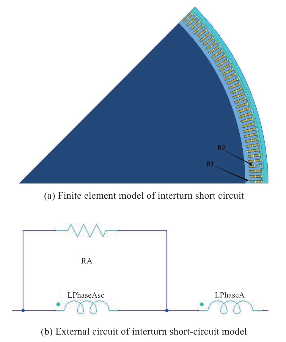
Fig.4 Interturn short-circuit models
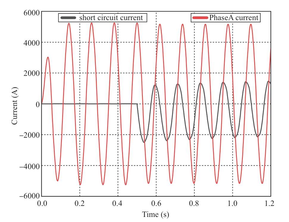
Fig.5 Contact resistance short-circuit current and a-phase current
2.3 Demagnetization fault simulation model is established
The permanent magnet direct drive generator has high efficiency,but the constituent material is prone to magnetic loss under vibration,shock,and high temperature;thus,the permanent magnet demagnetization fault was also investigated in this study.The demagnetization of a permanent magnet is either reversible or irreversible.The temperature performance index of magnetic material comprising NdFeB is poor.With the increasing temperature of the permanent magnet,an inflection point will occur in the second quadrant of the BH curve.A short-circuit fault in the permanent magnet motor will generate a large demagnetization field at the moment,equivalent to the addition of a reverse magnetic field.This will weaken the magnetic properties of the steel in the permanent magnet motor and cause demagnetization of the permanent magnet,inevitably producing reversible demagnetization.If the intensity of the demagnetization field is greater than that of the inflection point,it will cause irreversible demagnetization of the permanent magnet,weakening the performance of the respective motor.Thus,the motor will eventually be scrapped,resulting in serious economic losses[17-19].
Fig.6 displays the Id current curve for A-phase current at the angle of 90°.Id straight-axis current has demagnetization,therefore,the demagnetization current is all added to axis Id straight-axis.As the amplitude of Id demagnetization current increases,the demagnetization effect on the armature reaction becomes more serious.The inflection point was obtained from the demagnetization curve of the permanent magnet,and the moment of irreversible current was determined in the Id straightaxis current curve as 8.34 kA,approximately 2.27 times the rated current.The demagnetization curve and loop are presented in Fig.7(a),considering Id values less than this.Accordingly,the intensity of the reverse magnetic field is less than that of the inflection point,and reversible demagnetization occurs.For Id values greater than 2.27 times the rated current,the corresponding demagnetization curve and loop are shown in Fig.7(b).In this case,the intensity of the reverse magnetic field is greater than that of the inflection point,and irreversible demagnetization occurs[20].
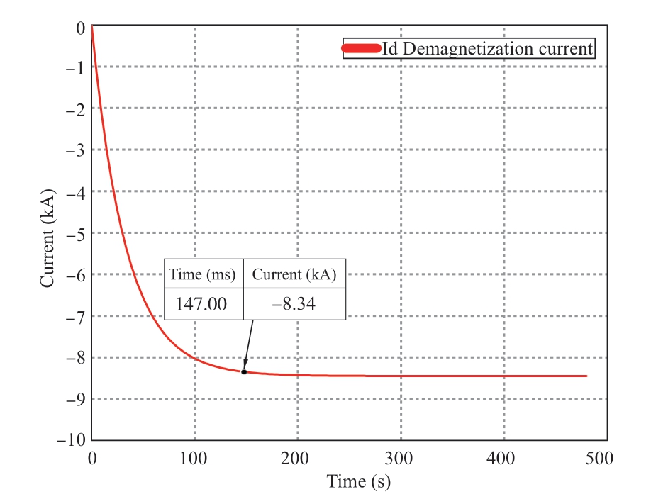
Fig.6 Id direct axis current
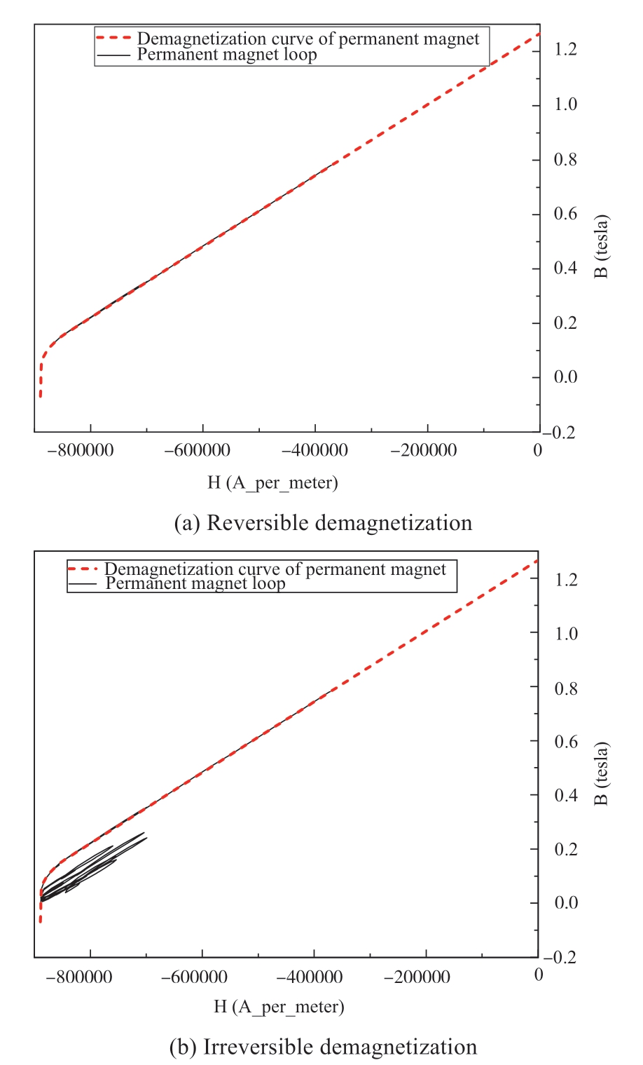
Fig.7 Demagnetization curves and loops
To further verify the demagnetization of magnetic steel when the threshold current is exceeded and observe the influence of demagnetization on the induced voltage,an analysis of the threshold current provides more accurate results than the traditional method involving the observation of the average magnetic density.The Root Mean Square of the induced voltage of A after demagnetization was approximately 406.62 V,indicating a small drop in amplitude compared with that of the no-load induced voltage of 411.93 V,before exceeding the threshold current by 2.27 times,as presented in Fig.8.Therefore,magnetic steel starts to demagnetize when the Id current is more than 2.27 times the threshold.
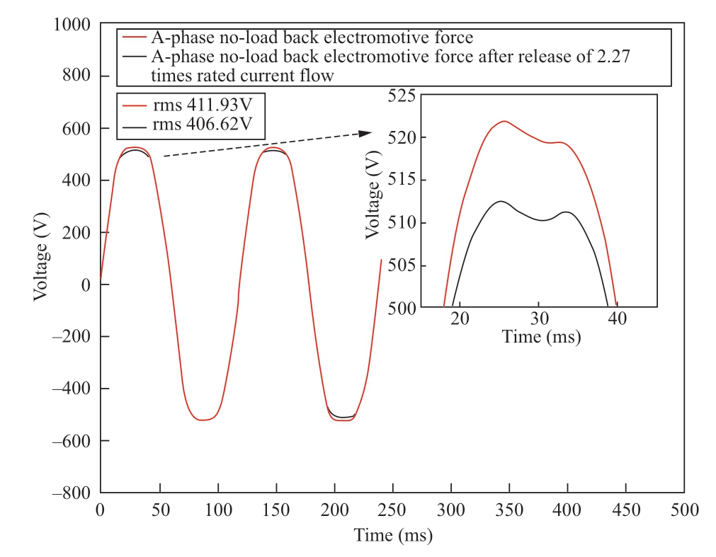
Fig.8 Induced voltage comparison
The traditional analytical calculation method was used to determine the average value for the maximum demagnetization operating point of a permanent magnet,but there are different degrees of local demagnetization when a permanent magnet is demagnetized.Therefore,the analytical calculation method cannot truly reflect the demagnetization of a permanent magnet and cannot be used as an accurate basis for demagnetization identification.In this study,ShinEtsu_N46MH-MF,a permanent magnet,was employed to simulate the demagnetization condition.The calculation of Maxwell permanent magnets based on the demagnetization rate involves the local demagnetization analysis of permanent magnets and overcomes the disadvantage that the degree of demagnetization is not easily observed.The demagnetization analysis was conducted on the permanent magnet at 80 °C,and the demagnetization range of the permanent magnet was more accurately reflected.In addition,the demagnetization rates(Demag)of permanent magnets with different Id values were analyzed under direct-axis current loading at 80 °C.The demagnetization rate of 0 signifies complete demagnetization,whereas that of 1 indicates no demagnetization,as depicted in Fig.9[21].Demag is given as
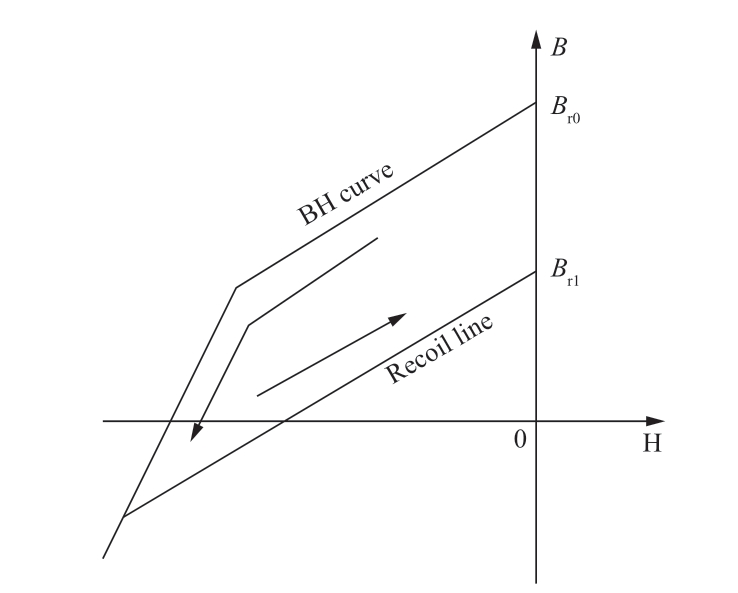
Fig.9 Rate of demagnetization
Fig.9 depicts that when two times the rated current is loaded,almost no demagnetization of the permanent magnet occurs,and the demagnetization rate is 1.000(Fig.10(a)).When the overload current is three times the rated current,weak demagnetization occurs at both ends of the permanent magnet,and the demagnetization rate is 0.8000(Fig.10(b)).When four times the rated current is loaded,local demagnetization occurs at both ends of the permanent magnet,and the demagnetization rate is 0.6000(Fig.10(c)).When the overload current is five times the rated current,the permanent magnet has a wide range of demagnetization,and the demagnetization rate is 0.2667(Fig.10(d)).When the overload current is more than six times the rated current,demagnetization at the two ends of the permanent magnet is almost complete,and the demagnetization rate is approximately 0(Figs.10(e)and(f)).Therefore,the simulation models of various demagnetization degrees were established by using the residual magnetic density Br of magnetic steel to study the changes in the internal electromagnetic characteristics of a permanent magnet generator at different demagnetization degrees[22].
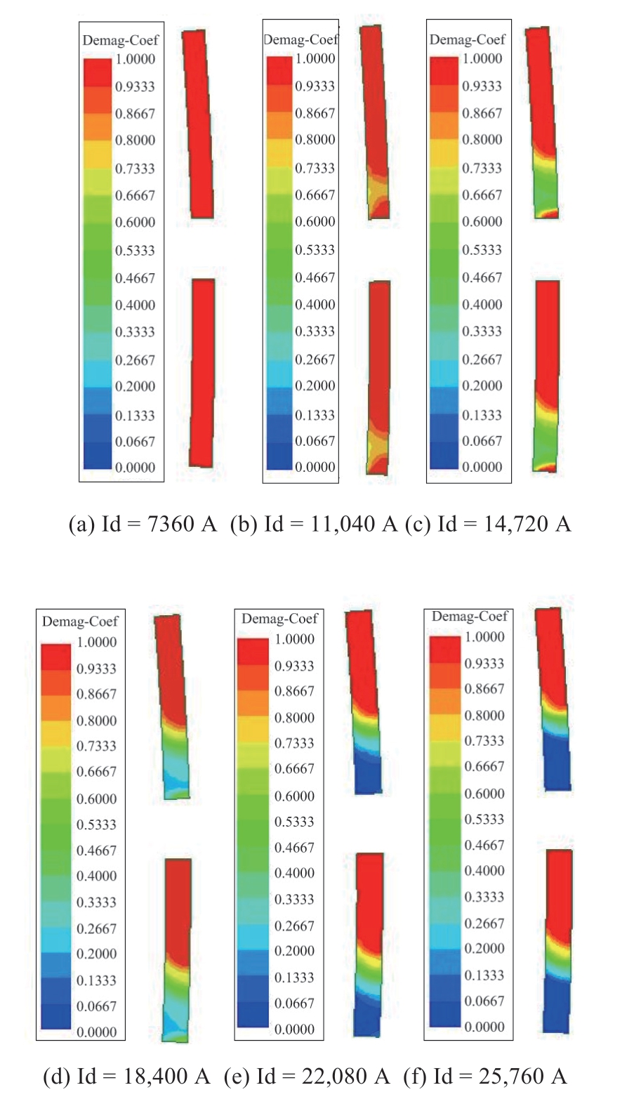
Fig.10 Cloud maps of demagnetization rates of permanent magnet under varying overload current
3 Wavelet packet analysis
Because Fourier transform cannot express nonstationary signals,windowed Fourier transform has the limitation of both time and frequency detection.The frequency resolution of wavelet transform in the high-frequency band is poor,whereas the time resolution in the low-frequency band is poor;thus,fault features are submerged and difficult to monitor.Wavelet packet transform can decompose both the low- and high-frequency parts of the signal and adaptively select the corresponding frequency band,considerably improving the time-frequency resolution;combined with the method of decomposition and reconstruction of frequency segments of abnormal nodes,the frequency segment is gradually screened.When the permanent magnet generator fails,the current and voltage waveforms will be distorted,and with the deepening of eccentricity,the degree of distortion will also increase.In this work,the db4 wavelet packet was adopted to decompose the electromagnetic signal under the fault state by five layers,and the abnormal node energy and coefficient waveforms were extracted to reduce the fault frequency range.Rotor eccentricity fault was determined at nodes(5,0),(5,1),(5,2),(5,3),and(5,5)(Fig.11(a)),whereas short-circuit fault was determined at nodes(5,2)and(5,3)(Fig.11(b)),and demagnetization fault was determined at node(5,3)(Fig.11(c)).Finally,the characteristic signal frequency band was reconstructed to verify the characteristic frequency,and the fault could be determined[23].
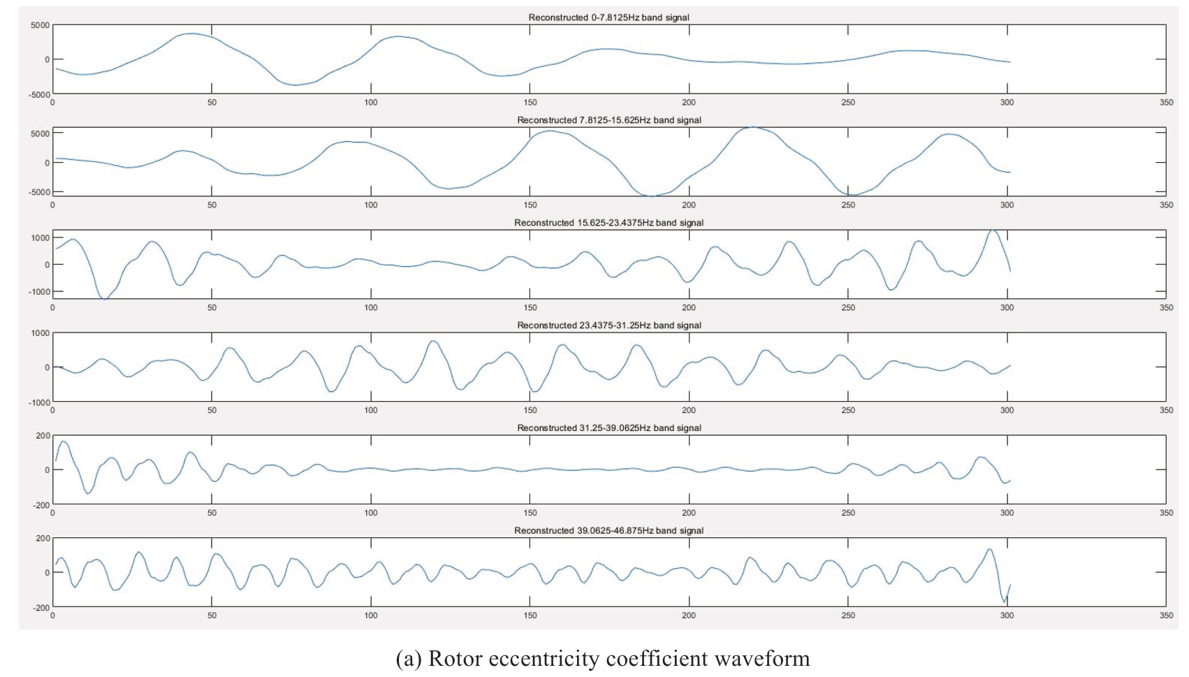
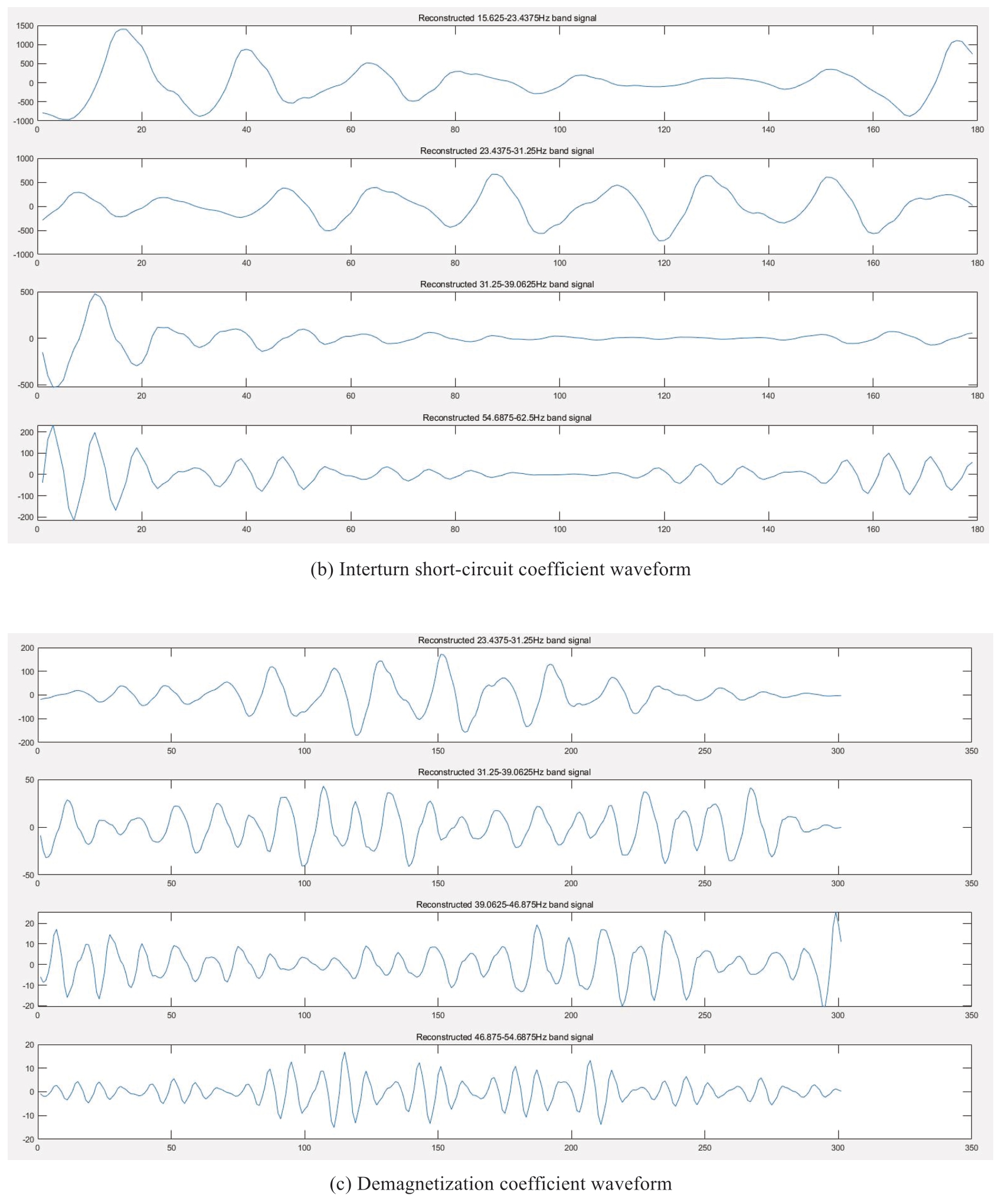
Fig.11 Coefficient of waveforms
4 Typical fault analysis
4.1 Eccentric fault analysis
Wind turbines comprise many moving components that are difficult to detect by sensors.Therefore,corresponding stator winding current data can be used to obtain the current without any additional equipment,and the fault can be monitored online.
The characteristic frequency of the stator current spectrum for the permanent magnet motor with eccentricity is expressed as:

Where nt is an arbitrary integer,Zr is the number of slots,nd is an arbitrary integer,s represents slip,p is a logarithm,n1 is an odd integer,and f0 is the rated frequency.
After the eccentricity of the permanent magnet generator,the air gap flux is distorted,and the fault is reflected in the current.The permanent magnet generator operates at synchronous speed,with no slip,and the rotor adopts a permanent magnet structure without a rotor slot.In general,only the fundamental frequency,nd,in the power supply is considered,and it is usually 1.Therefore,the formula for an eccentric fault in a permanent magnet generator can be obtained[24].
In formula(3),nd is an arbitrary integer,p is a logarithm,and f0 is the rated frequency.
An eccentric fault in a permanent magnet motor leads to uneven magnetic conductivity,resulting in asymmetric distribution of the air gap magnetic field.This influences the current of the motor,and a corresponding harmonic current will be generated in the stator windings.Therefore,stator current can be considered to judge eccentric faults in a generator.Based on the simulation of static and dynamic eccentric faults under rated load,the current harmonic amplitudes clearly increased at 4.98,6.64,9.97,and 11.63 Hz with increasing eccentricity according to wavelet packet analysis compared with the normal condition.Static eccentricity is displayed in Fig.12,whereas dynamic eccentricity is shown in Fig.13.When nd is 9 and 17,the results are consistent with the parameters of the permanent magnet generator used in the simulation.To verify the accuracy of characteristic frequency harmonics,the integer harmonics were analyzed.The rise and fall of the 5th and 7th harmonics can easily cause misjudgment,and the other harmonics exhibited no significant change.Therefore,the harmonics of 4.98,6.64,9.97,and 11.63 Hz were characteristic frequency harmonics of the rotor eccentricity fault in the permanent magnet generator[25-26].
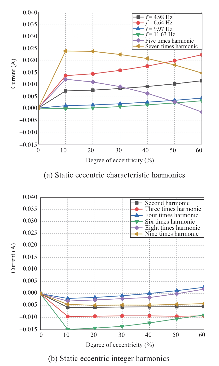
Fig.12 Static eccentricity frequency domains
From the rotor eccentricity fault of the permanent magnet generator,the characteristic frequencies of static eccentricity and dynamic eccentricity overlap,which needs to be further distinguished.With the increasing eccentricity of the permanent magnet generator rotor,the differentiation of harmonic amplitudes of 5 times(42Hz)is particularly obvious.In order to verify the correctness of the fifth harmonic as the characteristic frequency to distinguish the static eccentricity from the dynamic eccentricity,the relationship between the amplitude of other subharmonics in the stator current and the rotor eccentricity is analyzed.
Fig.14 shows the difference of stator current harmonic content between static eccentricity and dynamic eccentricity under different degrees of eccentricity.It is found that the amplitude variation of the two(16.8Hz),three(25.2Hz),four(33.6Hz),six(50.4Hz),seven(58.8Hz),eight(67.2Hz)and nine(75.6Hz)harmonics in the stator current of permanent magnet generator is almost zero.Therefore,the fifth(42 Hz)harmonics in the stator current can be used as characteristic frequency harmonics to distinguish the types of eccentric faults[27-28].
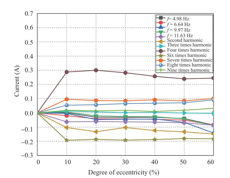
Fig.14 Comparison of current frequency domains regarding static eccentricity and dynamic eccentricity
Fig.13 Dynamic eccentricity frequency domains
4.2 Short-circuit fault analysis
The above finite element modeling method was adopted to study the interturn short circuit,and the current value of the rotor with different degrees of interturn short circuit was obtained.The wavelet packet analysis results were compared with the normal condition,and it was found that with the advancement of the short-circuit fault,the current harmonic amplitude of 17.76 Hz significantly increased,and that of 58.66 Hz significantly decreased.The amplitudes of the 3rd and 9th harmonics first increased and then decreased,and the other integral harmonics exhibited no obvious change,as in Fig.15.When the characteristic harmonic content has obvious changes,short circuit fault is easy to occur because the insulation layer of two adjacent coils between the same phase windings is damaged,so the cause can be found from this aspect to improve the monitoring efficiency[29-30].
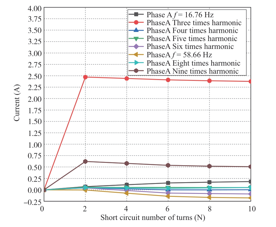
Fig.15 Current frequency domains for interturn short circuit
4.3 Demagnetization fault analysis
After the demagnetization of the NdFeB permanent magnet,the remanence of the permanent magnet decreases,and the induced electromotive force of stator winding decreases and becomes easy to extract.Subsequently,various voltage frequencies are produced.According to the wavelet packet analysis and the comparison with normal conditions,with increasing demagnetization fault,the third voltage harmonics exhibit a significant downward trend,as in Fig.16;the downward trend of a magnetic pole pair is nearly two times that of a single magnetic pole,as in Fig.17.Because of this,heat dissipation and the use of permanent magnet materials can reduce the fault[31-34].
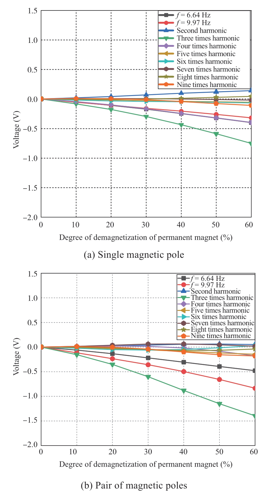
Fig.16 Voltage frequency domains of permanent magnet demagnetization voltage
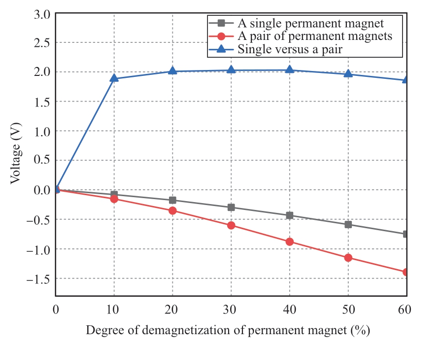
Fig.17 Comparison of voltage frequency domains regarding demagnetization fault in a single pole and a pair of poles
5 Conclusion
In the practical application of permanent magnet generators in wind turbines,electromagnetic signals collected by using current and voltage sensors can be used as diagnostic quantities.In this study,rotor eccentricity,stator winding interturn short-circuit,and demagnetization faults of permanent magnets were investigated by applying the Ansys software platform,and the stator current and induced voltage were evaluated by conducting finite element analysis.Moreover,wavelet packet analysis was employed to divide the frequency-band part of the signal at multiple levels,and the high-frequency part that was not subdivided in the multi-resolution analysis was further decomposed.The corresponding frequency band was selected adaptively to match the signal spectrum.The frequency segment was gradually screened by combining the decomposition and reconstruction of abnormal nodes to extract the fault feature accurately,thereby providing a theoretical basis for fault identification.The analysis of the frequency spectra for the stator current and the induced voltage is useful for the early monitoring of permanent magnet generator faults in wind turbines and will lead to better intuitiveness in engineering practices.After the fault type is confirmed,the software algorithm can locate the corresponding fault,thus providing an important research direction and breakthrough in this field.Accordingly,faults can be discovered in advance,allowing for appropriate maintenance planning.This topic can be further studied and explored in the future.
Acknowledgements
This work is supported by the National Natural Science Foundation of China(U22A20215 and 51537007)the Natural Science Foundation of LiaoNing Province(2021-YQ-09).
Declaration of Competing Interest
We declare that we have no conflict of interest.
References
[1]Zhao Z,Mei T Y,Li J Z,et al.(2022)Ventilation structure design and heat transfer analysis of 3.3MW permanent magnet direct drive wind generators.Energy Reports,8:1280-1286
[2]Agah G R,Rahideh A,Khodadadzadeh H,et al.(2022)Broken rotor bar and rotor eccentricity fault detection in induction motors using a combination of discrete wavelet transform and teager-Kaiser energy operator.IEEE Transactions on Energy Conversion,37(3):2199-2206
[3]Shaikh M F,Kim H J,Lee S B,et al.(2022)Online airgap flux based diagnosis of rotor eccentricity and field winding turn insulation faults in synchronous generators.IEEE Transactions on Energy Conversion,37(1):359-366
[4]Lasjerdi H,Nasiri-Gheidari Z,Tootoonchian F(2021)Static eccentricity fault diagnosis in wound-rotor resolvers.IEEE Sensors Journal,21(2):1424-1432
[5]Wei W D(2015)Analysis and diagnosis of three-phase induction motor rotor faults.Wuhan:Huazhong University of Science &Technology(in Chinese)
[6]Wei W D,Chen D Z,et al.(2015)Fault diagnosis of broken rotor bars of asynchronous motors based on stator winding signal current and noise signal.Electric Machines &Control Application,42(6):69-72
[7]Wang Y L.(2017)Research on the multi-fault intelligent diagnosis and separation methods for squirrel cage asynchronous motor.Taiyuan:Taiyuan University of Technology(in Chinese)
[8]Chen Y,Liang H,Wang C D,et al.(2020)Detection of stator inter-turn short-circuit fault in PMSM based on improved wavelet packet transform and signal fusion.Transactions of China Electrotechnical Society,35(S1):228-234(in Chinese)
[9]Chen X F(2011)Research and application of condition monitoring and fault diagnosis technology in wind turbines.Journal of Mechanical Engineering,47(9):45
[10]News,http://stock.10jqka.com.cn/20220114/c635994149.shtml,Accessed 14 January 2022
[11]Polat A,Ertuğrul Y D,Ergene L T(2015)Static,dynamic and mixed eccentricity of induction motor.2015 IEEE 10th International Symposium on Diagnostics for Electrical Machines,Power Electronics and Drives(SDEMPED).Guarda,Portugal.IEEE,284-288
[12]Krichen M,Ben Hadj N,Chaieb M,et al.(2021)Effects of airgap static eccentricity in permanent magnet synchronous motors by means of finite element analysis.2020 17th International Multi-Conference on Systems,Signals &Devices(SSD).Monastir,Tunisia.IEEE,422-427
[13]Gherabi Z,Benouzza N,Toumi D,et al.(2020)Eccentricity Fault diagnosis in PMSM using Motor Current Signature Analysis.2019 International Aegean Conference on Electrical Machines and Power Electronics(ACEMP)&2019 International Conference on Optimization of Electrical and Electronic Equipment(OPTIM).Istanbul,Turkey.IEEE,205-210
[14]Ebrahimi S H,Choux M,Huynh V K(2020)Modeling stator winding inter-turn short circuit faults in PMSMs including cross effects.2020 International Conference on Electrical Machines(ICEM).Gothenburg,Sweden.IEEE,1397-1403
[15]Dilovar G,Gandzha S(2020)Research of inter-turn short-circuit of a synchronous generator with permanent magnet.2020 Russian Workshop on Power Engineering and Automation of Metallurgy Industry:Research &Practice(PEAMI).Magnitogorsk,Russia.IEEE,128-132
[16]Xing Z X,Gao Y Z,Chen M Y,et al.(2022)Fault diagnosis of inter-turn short circuit of permanent magnet synchronous wind turbine under the random wind.2021 IEEE 2nd China International Youth Conference on Electrical Engineering(CIYCEE).Chengdu,China.IEEE,1-6
[17]Qi D D,Jing Y N,Zhang S Y(2021)The study of permanent magnet demagnetization in permanent magnet synchronous motor.2021 IEEE International Conference on Advances in Electrical Engineering and Computer Applications(AEECA).Dalian,China.IEEE,761-764
[18]Park Y,Fernandez D,Lee S B,et al.(2019)Online detection of rotor eccentricity and demagnetization faults in PMSMs based on Hall-effect field sensor measurements.IEEE Transactions on Industry Applications,55(3):2499-2509
[19]Drancă M,Chirca M,Breban Ş,et al.(2021)Thermal and demagnetization analysis of an axial-flux permanent magnet synchronous machine.2020 International Conference and Exposition on Electrical and Power Engineering(EPE).Iasi,Romania.IEEE,200-204
[20]Nakata A,Sanada M,Morimoto S,et al.(2022)Rotor structure for suppressing irreversible demagnetization of magnets in double-layered interior permanent magnet synchronous motors.2022 International Power Electronics Conference(IPEC-Himeji 2022- ECCE Asia).Himeji,Japan.IEEE,1005-1011
[21]Sarikprueck P,Lumyong P,Niroiana C N,et al.(2018)Magnetization of NdFeB permanent magnet considering demagnetization effect.2018 21st International Conference on Electrical Machines and Systems(ICEMS).Jeju,Korea(South).IEEE,649-652
[22]Khan M S,Okonkwo U V,Usman A,et al.(2018)Finite element modeling of demagnetization fault in permanent magnet direct current motors.2018 IEEE Power &Energy Society General Meeting(PESGM).Portland,OR,USA.IEEE,1-5
[23]Ping Z A,Juan Y,Ling W(2013)Fault detection of stator winding interturn short circuit in PMSM based on wavelet packet analysis.2013 Fifth International Conference on Measuring Technology and Mechatronics Automation.Hong Kong,China.IEEE,566-569
[24]Deng W Z,Zuo S G,Chen W,et al.(2022)Comparison of eccentricity impact on electromagnetic forces in internal- and external-rotor permanent magnet synchronous motors.IEEE Transactions on Transportation Electrification,8(1):1242-1254
[25]Ito F,Takeuchi K,Kotsugai T,et al.(2021)A study on asymmetry of electromagnetic force modes of permanent magnet synchronous motors with rotor eccentricity.IEEE Transactions on Magnetics,57(2):1-6
[26]Guo B C,Du Y L,Peng F,et al.(2022)Magnetic field calculation in axial flux permanent magnet motor with rotor eccentricity.IEEE Transactions on Magnetics,58(9):1-4
[27]Wang Y C,Liu K,Hua W,et al.(2022)Analysis and detection of rotor eccentricity in permanent magnet synchronous machines based on linear hall sensors.IEEE Transactions on Power Electronics,37(4):4719-4729
[28]Utomo R M,Yulistya Negara I M,et al.(2019)Wavelet filter selection analysis for air gap eccentricity in three phase induction motor.2018 International Seminar on Intelligent Technology and Its Applications(ISITIA).Bali,Indonesia.IEEE,199-204
[29]Kappes A D,Aprosin K I(2022)The detection analysis of the turn-to-turn fault in generators with a split winding.2022 5th International Youth Scientific and Technical Conference on Relay Protection and Automation(RPA).Moscow,Russian Federation.IEEE,1-13
[30]Dehina W,Boumehraz M,Kratz F,et al.(2019)Diagnosis and comparison between stator current analysis and vibration analysis of static eccentricity faults in the induction motor.2019 4th International Conference on Power Electronics and their Applications(ICPEA).Elazig,Turkey.IEEE,1-4
[31]Zhang S,Habetler T G(2018)Transient demagnetization characteristics of interior permanent magnet synchronous machines with stator inter-turn short circuit faults for automotive applications.2018 IEEE Energy Conversion Congress and Exposition(ECCE).Portland,OR,USA.IEEE,1661-1667
[32]Zhang C F,Wu G P,Rong F,et al.(2018)Robust fault-tolerant predictive current control for permanent magnet synchronous motors considering demagnetization fault.IEEE Transactions on Industrial Electronics,65(7):5324-5334
[33]Attestog S,Van Khang H,Robbersmyr K G(2019)Detecting eccentricity and demagnetization fault of permanent magnet synchronous generators in transient state.2019 22nd International Conference on Electrical Machines and Systems(ICEMS).Harbin,China.IEEE,1-5
[34]Darbandeh P Q,Ardebili M,Aliyari Shoorehdeli M,et al.(2022)Diagnosis of partial demagnetization in permanent magnet synchronous machine using wavelet packet transform.2022 International Conference on Electrical Machines(ICEM).Valencia,Spain.IEEE,1602-1608
Received:15 November 2022/Accepted:3 January 2023/Published:25 Feburary 2023
 Guangwei Liu
liu-gw@outlook.com
Wenbin Yu
1181939448 @qq.com
Xiaodong Wang
11661938 @qq.com
Yun Teng
tengyun@sut.edu.cn
Zhe Chen
zch@et.aau.dk
2096-5117/© 2023 Global Energy Interconnection Development and Cooperation Organization.Production and hosting by Elsevier B.V.on behalf of KeAi Communications Co.,Ltd.This is an open access article under the CC BY-NC-ND license(http://creativecommons.org/licenses/by-nc-nd/4.0/).
Biographies

Guangwei Liu received his B.Eng.,M.Sc.and Ph.D.degrees in electrical engineering from Shenyang University of Technology,Shenyang,China,in 2005,2008 and 2015 separately.He joined the Shenyang University of Technology in 2008,where he is currently a full professor in school of electrical engineering.His major research interests and activities are in the areas of permanent magnet electrical machines and its drive.

Wenbin Yu is currently pursuing the master’s degree in electrical engineering with Shenyang University of Technology,Shenyang.His research Interests include Analysis of Electromagnetic Characteristics of Typical Faults of Permanent Magnet Wind Generator.

Xiaodong Wang received his B.Eng.,M.Sc.degrees in computer application in 2001 and 2004,Ph.D.degrees in electrical engineering in 2011,from Shenyang University of Technology,Shenyang,China.He joined the Shenyang University of Technology in 2004,where he is currently a full professor in school of electrical engineering.His major research interests and activities are in the areas of wind turbine and its operation condition monitoring.

Yun Teng received his doctor’s degree in electrical engineering from Shenyang University of Technology,Shenyang,China,in 2009.He joined the Shenyang University of Technology in 2010,where he is currently a professor in electrical engineering.He is a standing director as the IEEE PES DC Distribution Network Technical Subcommittee.His research interests include multi-energy system dispatching automation and smart grid control theory.

Zhe Chen received his B.Eng.and M.Sc.degrees from Northeast China Institute of Electric Power Engineering,Jilin City,China,and his Ph.D.degree from the University of Durham,Durham,U.K.He is a full professor with the Department of Energy Technology,Aalborg University,Aalborg,Denmark,where he is the leader of the Wind Power System Research program in the Department of Energy Technology.He is also the Danish Principle Investigator for Wind Energy of the Sino-Danish Centre for Education and Research.His research areas are power systems,power electronics and electric machines;and his main current research interests are wind energy and modern power systems.
(Editor Dawei Wang)
