0 Introduction
The safe and reliable operation of a power system requires full-domain and high-precision positioning[1, 2].For example, various services, such as safety management, control of mobile operation devices, and the geological environment monitoring services in a power grid construction site require decimeter-level positioning accuracy [3, 4], while the positioning services of power grid facilities such as substations, transmission towers, and power line inspections in areas with frequent geological disasters require centimeter-level positioning accuracy[5].Developed in 2020, the Beidou-3 navigation satellite system (BDS-3) is based on the technologies of BDS-2 and BDS-1; however, BDS-3 uses more advanced calibration models and technologies to provide global navigation and positioning, short message communication, high-precision timing, and other functions worldwide [6-8].Compared with other global satellite navigation systems, such as the global positioning system (GPS), BDS-3 offers the advantages of full-domain and high-precision positioning by using groundbased augmentation [9-12].However, several challenges remain in the wide-range deployment of BDS-3 in power systems for full-domain and high-precision positioning.Details are introduced as follows.
First, the complex electromagnetic interference caused by the operation of high-voltage electrical equipment and power electronic components [13]increases the error in the pseudo range observations, which decreases the navigation and positioning accuracy based on BDS-3 [14,15].Second, traditional error elimination methods, suchas Wiener filtering, require prior knowledge and statistical characteristics of both desired signal and electromagnetic interference [16], which are infeasible considering the highly dynamic and complex application environment in which the power system operates [17, 18].Consequently,traditional methods result in incomplete error elimination and poor positioning accuracy.
Existing studies have explored BDS-3-based positioning technology.Koval et al.[19]proposed a time synchronization scheme based on Internet Protocol (IP)technologies, which enables monitoring of synchronization signals of BDS-3 in real time and provides guaranteed quality indicators.Li et al.[20]introduced a positioning calibration approach to optimize the stability of differential code bias of BDS-3 satellites.However, the above studies ignore the complex application scenarios of power systems and the influence of the electromagnetic interference, primarily because the pseudo range error caused by electromagnetic interference results in inaccurate positioning.Alfarozi et al.[21]reported a square wave quadrature amplitude modulation scheme where the decoder employs a wiener filter.The scheme performs better in terms of error elimination than the theoretical decoding scheme.However, it relies on perfectly known prior knowledge of signal and interference statistical characteristics, which cannot be applied to scenarios where the electromagnetic interference characteristics are unknown in a power system.
Adaptive filtering methods, particularly least mean square (LMS) filtering, with a range of advantages, such as low algorithm complexity, easy implementation, and high stability, have been extensively used for error elimination and positioning accuracy improvement.For instance, Hu et al.[22]proposed a method for analyzing the nonlinear effects of a power amplifier on adaptive arrays, where LMS filtering was utilized to achieve error elimination.Liu et al.[23]proposed an active vibration control system by applying an LMS adaptive filter as the controller,which suppresses vibration of the micron positioning stage to promote positioning stability.However, the standard LMS filtering used in the above studies is unsuitable for eliminating rapidly changing electromagnetic interference in power system positioning, resulting in slow convergence and low accuracy.
To address the aforementioned problems, we propose a back propagation (BP) neural network-improved LMS adaptive filtering method for the full-domain and highprecision power system positioning based on BDS-3.First,BP-LMS filters the observed pseudo range, and then inputs the input value, output value, and desired value of filtering into the BP neural network to obtain the compensated value to further compensate the pseudo range and eliminate the impact of electromagnetic interference, which enhances the accuracy of power system positioning and the convergence speed.Numerous simulation results reveal that the proposed BP-LMS exhibits superior performance in positioning accuracy and error elimination.
The remainder of this article is organized as follows.BDS-3 is briefly introduced in Section 1.BP-LMS adaptive filtering-based full-domain and high-precision power system positioning are presented in Section 2.The simulation results are presented in Section 3.Finally, the article is concluded in Section 4.
1 BDS-3 features
BDS-3 refers to a global navigation satellite system developed independently by China, which comprises a space satellite system, ground control system, and user devices.In the space satellite system, there are two geosynchronous satellites that perform the relay task of two-way radio signals between the ground control center and the user devices.The ground control center is primarily responsible for the reception and generation of wireless signals, as well as the monitoring and management of the entire system.The user device receives the positioning signals sent by the ground control center.The BDS-1 system was deployed and completed in 2003, which only provides positioning and navigation services to the Asia-Pacific region.In 2012,BDS-2 was established with 14 networking satellites to officially provide passive positioning services to the Asia-Pacific region.Following that, China constructed an allweather and real-time satellite navigation and positioning system BDS-3 for global service by 2020.The BDS-3 system comprises five geostationary orbit satellites, three synchronous inclined orbit satellites, and twenty-seven mid-orbit satellites to provide high-precision and reliable positioning services.Compared with BDS-2, BDS-3 provides an open service and authorized service.Moreover,BDS-3 adopts several new technologies, including better rubidium atomic clocks, new communication link,ionospheric delay correction model, and a series of new frequency point navigation signals, which provide BDS-3 with the advantage of global constellation, inter-satellite link, and multi-system interoperation.
2 BP-LMS adaptive filtering based fulldomain and high-precision power system positioning
In this section, the principle of pseudo rangepositioning based on BDS-3 is introduced.Based on it,a BP neural network improved LSM filtering method is proposed for eliminating the pseudo range error caused by electromagnetic interference and enhance the power system positioning precision.
2.1 Principle of pseudo range positioning based on BDS-3
The distance between the power device and the satellite is called the pseudo range.The principle of pseudo range positioning based on BDS-3 is shown in Fig.1.

Fig.1 Schematic of pseudo range positioning based on BDS-3
ConsideringN power devices deployed in the grid and MBDS-3 satellites, the sets are U={U 1,...,U n ,...,UN}and S={S1 ,...,S m ,...,S M}, respectively.Each BDS-3 satellite transmits its position coordinate information to the power devices to assist in device positioning.The device receives the coordinate information of BDS-3 satellite via the signal receiver.As illustrated in Fig.1, there is a clock difference between the satellite time of satelliteSm and the standard system time, i.e.,Tm,s.The time thatSm transmits the position coordinate information isTm , and the actual transmission delay from satelliteSm to device Un is Tm,n.Additionally,the clock difference between the receiver time of deviceUn and the system time is Tn,s.Accordingly, the time when Un receives the positional coordinate information is given by
The observed transmission delay from satellite Sm to device Un is
Therefore, the observed pseudo range value is
wherec denotes the speed of light.The real distance between Sm and Un is
The clock difference between Sm and Un is
Based on (3) and (4), (5) can be rewritten as
Generally, power devices are deployed in grid with complex electromagnetic interference; therefore, the pseudo range ρn,m between Un and Smshould consider the impact of electromagnetic interference, which is given by
where βn,mindicates the error caused by electromagnetic interference.Moreover, owing to the Earth rotation error,the coordinate of Sm received by the power devices, i.e.,(xm , y m , z m ), is deviated from the actual coordinate, which needs to be corrected as

whereϖdenotes the Earth rotation speed.Denoting the coordinate of the device Un as (xn , y n , zn ), the real distance between Sm and Un is given by
The coordinate of the device can be obtained based on the pseudo range, clock difference between the satellite and the device, and error caused by the environment.The threedimensional coordinate (xm , y m , z m )and pseudo range ρn,m between device Un and satellite Sm are known, while the clock differenceδn,m is unknown.Therefore, by measuring the pseudo range between deviceUn and several satellites,the coordinates ofUncan be obtained by solving the following equations.

Based on the relationship between device time and satellite time, the clock difference between device Un and all satellites is the same, i.e.,δn , 1 = δ n , 2 = δ n , 3 =δn ,4.Therefore, at least four satellites are required to obtain the three-dimensional coordinate of Un.For the error βn,m, which cannot be observed, we propose using adaptive filtering to reduce the impact of electromagnetic interference on device coordinate calculation.
2.2 Adaptive filtering principle
Adaptive filtering is an optimal filtering method developed on the basis of linear filtering [24, 25].The principle of adaptive filtering is illustrated in Fig.2.

Fig.2 Schematic of adaptive filtering
Here,p(j)andq(j)denote the input and output signal value at timejrespectively.ϕ(j)represents the reference signal value or the desired signal value at timej.The error signale(j)corresponds to the difference betweenϕ(j)andq(j).The filtering parameters of the adaptive filter are automatically adjusted according to the value ofe(j)to make the output q(j+1)closer to the desired reference signalϕ(j+1)at timej+1.The core of adaptive filtering involves an algorithm to adaptively adjust the filtering parameters to better adapt to the filtering requirements.
2.3 LMS adaptive filtering
LMS adaptive filtering method with simple structure and easy implementation is adopted, which includes filtering process and adaptive process [26, 27].
In aK -order LMS adaptive filtering process,we define the set of input states as X(n) =[x(n)x(n − 1 ),...,x(n − K + 1 )]T, and the set of filtering parameters asW ( n) = [w0 ( n),w 1 ( n ) ,...,w k − 1 ( n)]T.Subsequently, the output is given by
Denoting the desired output of the filtering asd(n), the errore(n)is given by
The objective of the LMS adaptive filtering is to minimize the mean square error functionJ(W)according to the minimum mean square error (MMSE) criterion, where J(W)is given by
To minimizeJ(W), the derivative ofJ(W)with respect toWshould be calculated and set to zero.However, as expressed in (12), the mathematical expectation should be calculated and all historical data and current data are required to estimate the statistical value of the current signal,which is unrealistic in practical engineering.Therefore, the instantaneous gradient∇J is used instead of the expectation derivative, which is given by

Subsequently, the LMS filtering parameters are updated as
whereµsymbolizes the step factor.The adaptive filtering ends when the number of iterations or the error accuracy is satisfied.LMS adaptive filters have obvious advantages in solving linear problems.However, traditional linear control step factor method of LMS adaptive filtering cannot match the complex electromagnetic interference environment in the power system, resulting in slow convergence speed and low accuracy.
2.4 BP-LMS adaptive filtering-based error elimination for BDS-3 power system positioning
A BP-LMS adaptive filtering method is proposed to eliminate the error caused by the electromagnetic interference in the BDS-3 power system positioning.The flowchart and schematic diagram of the proposed scheme are depicted in Fig.3 and Fig.4.Compared with LMS filtering, BP-LMS adaptive filtering inputs the output of LMS filtering into the BP neural network.The output of the BP neural network is used to compensate the output of the LMS filtering and update the filtering parameters,which accelerates the convergence speed of the filtering and improves the error elimination accuracy.
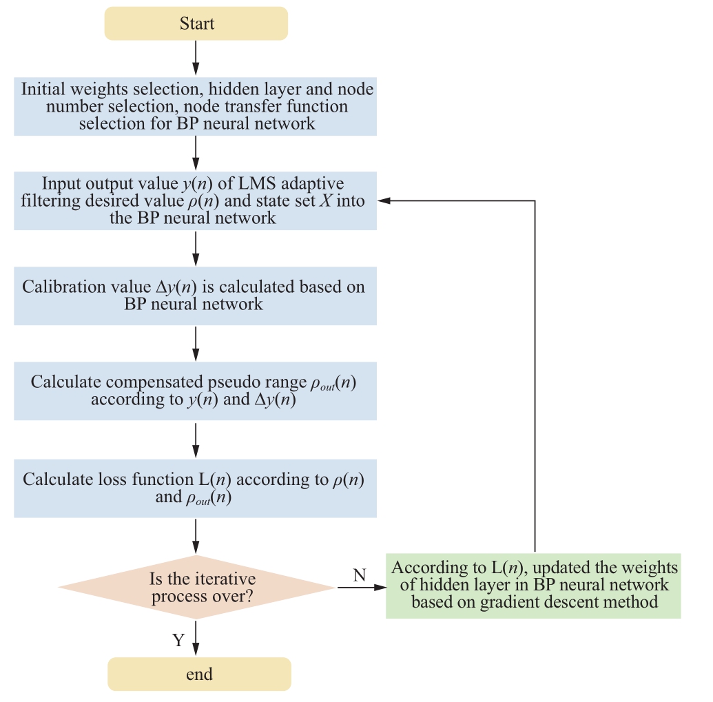
Fig.3 Flowchart of the BP-LMS adaptive filtering-based error elimination method
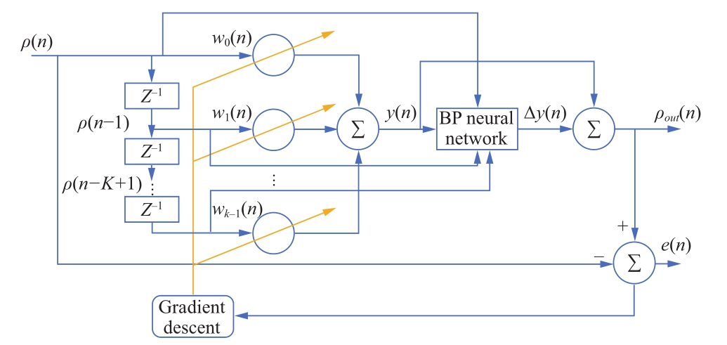
Fig.4 BP-LMS adaptive filtering-based error elimination for BDS-3 power system positioning
The set of input states to the BP-LMS is X ={ρ( n ) ,ρ ( n − 1 )...,,...,ρ (n − K +1)}, where ρ(n) is the observed pseudo range, which is given by
s(n) represents the effective pseudo range, and b(n)represents the electromagnetic interference described by the alpha stable distributed noise model.s(n) and b(n) are statistically independent of each other.
In the block diagram, the desired value is set as ρ(n).In the filtering process, if the output value is closer to the desired value, a faster convergence speed and more accurate result can be obtained.Therefore, in each iteration,the output value y(n) of LMS adaptive filtering, desired valueρ(n), and input state setXare input into the BP neural network to output the calibration value∆y(n).Subsequently, the output of LMS adaptive filteringy(n)is combined with the output of the BP neural network∆y(n),and the compensated pseudo range is given by
The procedure of the BP neural network structure design is introduced as follows [28].
1) Initial weight selection
The initial weight of the BP neural network directly affects the performance of the entire neural network.We select the random distribution within the closed interval[-1,1]as the initial weight.
2) Hidden layer and node number selection
We adopt the three-layer BP neural network with one input layer, one hidden layer, and one output layer.The dimensions of input and output variables determine the number of neural nodes in the three layers.In each iteration,the output value of LMS filtering y(n), desired value ρ(n),andN-dimensional setXare input to the BP neural network.Therefore, the neural network has to containN+2nodes in the input layer and one node in the output layer.The number of nodes in the hidden layerH is given by
whereλis an integer between 0 and 10.
3) Other neural network parameter selection
In this study, we select tangentS-type functionf(x)as the node transfer function, which is given by
During the training process, the loss function is utilized to evaluate the output of BP-LMS, which is set as the variance of the compensated output value and the desired value and given by
In the next iteration, the weights of the hidden layer in the BP neural network are updated based on the gradient descent method according to the loss functionL(n).
3 Simulation results
The proposed algorithm was simulated to accurately verify the performance of BP-LMS in terms of accuracy,filtered pseudo range, error, and standard deviation of coordinates.The results are compared with the traditional LMS and normalized least mean square (NLMS) algorithms.We used the pseudo range signal at B1C frequency of BDS-3 to conduct the simulation.The simulation parameters are summarized in Table 1 [29].In total, ten BDS-3 satellites were considered for power system pseudo-distance estimation, and 2000 sets of data were collected by the LMS [30], NLMS [31], and BP-LMS filters, respectively.The output results were used for simulation comparison in terms of accuracy, filtered pseudo range, error, and standard deviation of coordinates.If the order of the LMS filter is too high, it will result in high computation complexity, poor tracking performance, low system stability, and steady-state errors.On the contrary, if the order of LMS filter is too low,it will result in slow convergence speed, large step size, and poor filtering effect on the signal.Therefore, we set the order of the LMS filter as K=5 in the simulation.NLMS adds a normalization step in the process of updating parameters of the adaptive filter, which reduces the influence of noise on filtering results to a certain extent.NLMS can be improved by the BP neural network; however, some additional steps are required to reduce the computational overhead caused by normalization.Compared with BP-LMS, the combination of BP neural network and NLMS only achieves a small performance improvement at the cost of an extremely high computational overhead.Therefore, the combination of BP neural network and NLMS and the resulting tradeoff between the performance improvement and computational overhead are beyond the scope of this article and can be studied in future work.
Table 1 Simulation Parameters

Figure 5 illustrates the pseudo range comparison before and after filtering.The normalized minimum mean square error (NLMS) is used for comparison.NLMS is an improved algorithm of the traditional LMS algorithm, and its step factor is designed as the inverse of the square of the two-norm of the current input signal set.Moreover, LMS,NLMS, and BP-LMS effectively eliminate the influence of electromagnetic interference caused by the complex environment in the power system on the pseudo range measurement.Compared with LMS and NLMS, BP-LMS has better convergence speed and adaptation with dynamic electromagnetic interference owing to the employment of BP neural network to improve filter parameter updating.

Fig.5 Pseudometric comparison of the BDS-3 positioning and navigation system before and after filtering
Standard deviation is used to judge the position dispersion degree of receiver before and after filtering.To highlight the superiority of the proposed method, the discreteness degree of receiver position after BP-LMS filtering is compared with that after LMS filtering and NLMS filtering.Figure 6 presents the comparison of standard deviations of position in the X, Y, and Z axis of the receiver computed according to the pseudo range.Compared with LMS, the average standard deviations of the X-axis,Y-axis, and Z-axis are decreased by 1.6409 m, 1.5625 m,and 1.6458 m, respectively.Compared with NLMS, the average standard deviations of the X-axis, Y-axis, and Z-axis are decreased by 1.5958 m, 1.4919 m, and 1.6125 m,respectively.
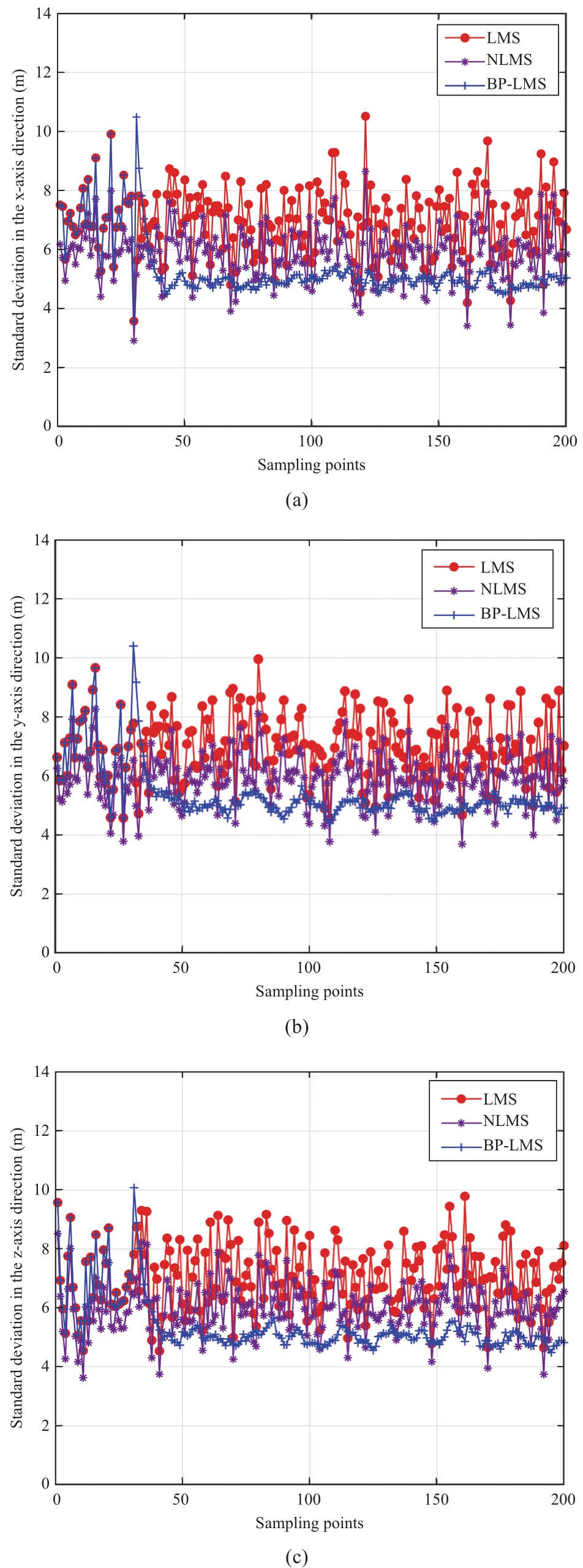
Fig.6 Standard deviation in X, Y and Z axes
Figure 7 shows the positioning error of 200 devices.The positioning error of BP-LMS is lower than that of LMS and NLMS.It is because the BP-LMS algorithm can interact with the environment, adapt to the dynamic change of electromagnetic interference, and avoid error iteration during parameter update, which results in better error elimination.
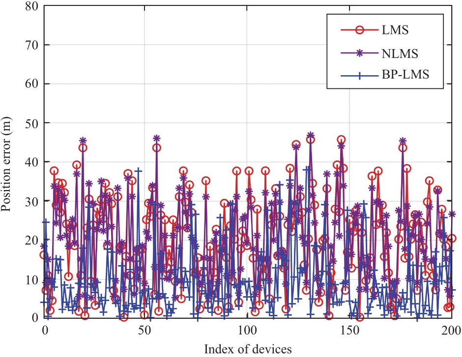
Fig.7 Positioning error comparison
Figure 8 presents the comparison of positioning deviation.We divide the positional errors shown in Fig.4 into five intervals: (0, 10), (10, 20), (20, 30), (30, 40), and(40, 50).The quantity of devices in each interval is counted.If most of the devices are distributed in smaller intervals,it indicates higher positioning accuracy.BP-LMS has the highest proportion of devices in the smallest error interval(0, 10), which is 70.71% and 53.85% higher than LMS and NLMS, respectively.In contrast, LMS has the highest proportion of devices in the interval (20, 30).

Fig.8 Positioning deviation comparison
Figure 9 depicts the filtering error versus the number of iterations.The filtering error is defined as the square of the difference between the filter output and the measured data during the BP-LMS adaptive filtering process.Compared with NLMS and LMS, the filtering error of BP-LMS is decreased by 57.14% and 51.38%, respectively.Meanwhile,the filtering error tends to be stable at 300 iterations.BPLMS significantly improves the precision and robustness of LMS filtering and has better filtering performance.By using the fitting and learning ability of BP neural network skillfully, BP-LMS inputs the data output of LMS filter into the BP neural network to output the compensation to modify the filtering, which effectively avoids the shortcoming of cumulative filtering divergence over iterations.
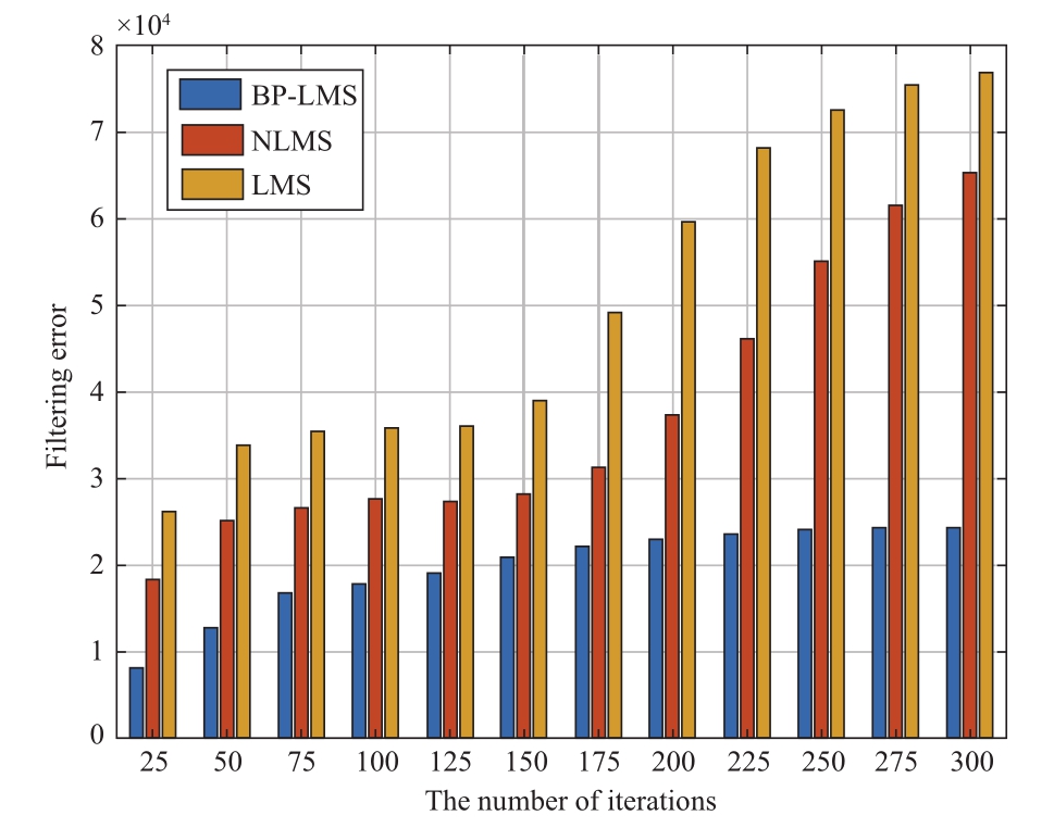
Fig.9 Filtering error versus the number of iterations
4 Conclusion
This study investigated the BDS-3 full-domain and highprecision power system positioning problem.A BP-LMS adaptive filtering method was proposed to eliminate the error caused by the electromagnetic interference and improve the accuracy of power system positioning.Compared with LMS and NLMS, BP-LMS improves the positioning accuracy of X, Y, Z-axes coordinates.However, the proposed method does not consider the statistical characteristics of electromagnetic interference.The error elimination and filtering accuracy performance can be further improved if the statistical characteristics of electromagnetic interference is known.In future work, we will investigate the statistical characteristics of electromagnetic interference to further improve the filtering performance.Moreover, we will aim to use the improved BP-LMS to solve the problem caused by signal similarity, where BP-LMS gets stuck in a local optimum, which will improve the positioning accuracy.
Acknowledgements
This work was supported by the Science and Technology Project of the China Southern Power Grid Company Limited under Grant Number (GDKJXM20202001).
Declaration of Competing Interest
We declare that we have no conflicts of interest.
References
[1]Lu X, Wang J, Liu G, et al.(2021) Station-and-networkcoordinated planning of integrated energy system considering integrated demand response, Global Energy Interconnection,4(1): 39-47
[2]Zhang J, Ye Y, Hu C, et al.(2021) Architecture design and demand analysis on application layer of standard system for ubiquitous power internet of things, Global Energy Interconnection, 4(3): 304-314
[3]Liao H, Mu Y, Zhou Z, et al.(2021) Blockchain and learningbased secure and intelligent task offloading for vehicular fog computing.IEEE Transactions on Intelligent Transportation Systems, 22(7): 4051-4063
[4]Kong X, Xu Y, Jiao Z, et al.(2020) Fault location technology for power system based on information about the power internet of things.IEEE Transactions on Industrial Informatics, 16(10):6682-6692
[5]Lin Y, Bie Z, Qiu A (2018) A review of key strategies in realizing power system resilience, Global Energy Interconnection, 1(1):70-78
[6]Liao H, Zhou Z, Kong W, et al.(2021) Learning-based intentaware task offloading for air-ground integrated vehicular edge computing.IEEE Transactions on Intelligent Transportation Systems, 22(8): 5127-5139.
[7]Huang W, Defraigne P (2016) BeiDou time transfer with the standard CGGTTS.IEEE Transactions on Ultrasonics,Ferroelectrics, and Frequency Control, 63(7): 1005-1012
[8]Hu C, Tian Y, Yang X, et al.(2016) Background ionosphere effects on geosynchronous SAR focusing: theoretical analysis and verification based on the BeiDou navigation satellite system(BDS).IEEE Journal of Selected Topics in Applied Earth Observations and Remote Sensing, 9(3): 1143-1162
[9]Deng J, Ke F, Chen R, et al.(2020) A method for real-time decimeter solutions over long baseline with BDS triple-frequency signals.IEEE Sensors Journal, 20(6): 3151-3161
[10]Zhao S, Zhang X, Cui X, et al.(2021) A closed-form localization method utilizing pseudorange measurements from two nonsynchronized positioning systems.IEEE Internet of Things Journal, 8(2): 1082-1094
[11]Li Z, Huang C, Sun Z, et al.(2022) BeiDou-based passive multistatic radar maritime moving target detection technique via space–time hybrid integration processing.IEEE Transactions on Geoscience and Remote Sensing, 60: 1-13
[12]Li B, Feng Y, Gao W, et al.(2015) Real-time kinematic positioning over long baselines using triple-frequency BeiDou signals.IEEE Transactions on Aerospace and Electronic Systems,51(4): 3254-3269
[13]Liao H, Wang Z, Zhou Z, et al.(2022) Blockchain and semidistributed learning-based secure and low-latency computation offloading in space-air-ground-integrated power IoT.IEEE Journal of Selected Topics in Signal Processing, 16(3): 381-394
[14]Li Z, Han Z, Yang M, et al.(2020) Multi-stage power source and grid coordination planning method considering grid uniformity,Global Energy Interconnection, 3(04): 303-312
[15]Wu J, Guo Q, Yue C, et al.(2020) Special electromagnetic interference in the ionosphere directly correlated with power system.IEEE Transactions on Electromagnetic Compatibility,662(3): 947-954
[16]Chang S, Wu H (2022) Tensor wiener filter.IEEE Transactions on Signal Processing, 70: 410-422
[17]Brinkerink M, Deane P, Collins S, et al.(2018) Developing a global interconnected power system model, Global Energy Interconnection, 1(03): 330-343
[18]Liao H, Zhou Z, Zhao X, et al.(2021) Learning-based queueaware task offloading and resource allocation for space-airground-integrated power IoT.IEEE Internet of Things Journal,8(7): 5250-5263
[19]Koval V, Osinskiy O, Lysenko V, et al.(2019) Infocommunication technologies and networks for multichannel monitoring of synchronization signals of SMART grid and microgrid electrical systems, In: Proceeding of 2019 IEEE International Scientific-Practical Conference Problems of Infocommunications, Science and Technology (PIC S&T), Kyiv, Ukraine, 08-11, Oct 2019
[20]Li Z, Yuan Y, Fan L, et al.(2014) Determination of the differential code bias for current BDS satellites.IEEE Transactions on Geoscience and Remote Sensing, 52(7): 3968-3979
[21]Alfarozi S A I, Pasupa K, Hashizume H, et al.(2019) Robust and unified VLC decoding system for square wave quadrature amplitude modulation using deep learning approach.IEEE Access, 7: 163262-163276
[22]Hu C, Chang D (2016) Nonlinear effects of power amplifiers on adaptive antenna systems.IEEE Transactions on Antennas and Propagation, 64(4): 1444-1453
[23]Liu Y, Lee H (2012) Adaptive Filtered-X LMS algorithm for active vibration control on micron positioning stage.In: 2012 International Conference on Control, Automation and Information Sciences (ICCAIS), Saigon, Vietnam, 26-29, Nov 2012
[24]Suresh S, Lal S (2017) Two-dimensional CS adaptive FIR wiener filtering algorithm for the denoising of satellite images.IEEE Journal of Selected Topics in Applied Earth Observations and Remote Sensing, 10(12): 5245-5257
[25]Wu W, Xiao Y, Lin J, et al.(2021) An efficient filter bank structure for adaptive notch filtering and applications.IEEE/ACM Transactions on Audio, Speech, and Language Processing,29: 3226-3241
[26]Mula S, Gogineni V, Dhar A, et al.(2018) Algorithm and VLSI architecture design of proportionate-type LMS adaptive filters for sparse system identification.IEEE Transactions on Very Large Scale Integration (VLSI) Systems, 26(9): 1750-1762
[27]Das B, Chakraborty M (2014) Sparse adaptive filtering by an adaptive convex combination of the LMS and the ZA-LMS algorithms.IEEE Transactions on Circuits and Systems I:Regular Papers, 61(5): 1499-1507
[28]Zhu X, Li J, Liu Q, et al.(2022) Use of a BP neural network and meteorological data for generating spatiotemporally continuous LAI time series.IEEE Transactions on Geoscience and Remote Sensing, 60: 1-14
[29]Wang W, Zhu Q, Wang Z, et al.(2022).Research on indoor positioning algorithm based on SAGA-BP neural network.IEEE Sensors Journal, 22(4): 3736-3744
[30]Yong J, Lu H, Dong Z (2021) Adaptive digital self-interference cancellation based on fractional order LMS in LFMCW radar.Journal of Systems Engineering and Electronics, 32(3): 573-583
[31]Ali A, Moinuddin M (2022) NLMS is more robust to inputcorrelation than LMS: A Proof.IEEE Signal Processing Letters,29: 279-283
Received: 10 August 2022/ Accepted: 11 November 2022/ Published: 25 December 2022
Jiangang Lu
lujiangang@gddd.csg.cn
Ruifeng Zhao
ruifzhao@126.com
Wenxin Guo
guowenxin1985@126.com
Wenjie Zheng
zhengwenjie@gddky.csg.cn
Shiming Li
365419377 @qq.com
Biographies

Ruifeng Zhao received the Ph.D.degree from Chongqing University, Chongqing, China in 2013.Currently, he is a senior engineer in Guangdong Power Grid Co., Ltd.Power Dispatching and Control Center.His research interests include operation and control and optimization techniques in power systems,distribution network automation, network information security of power systems.

Jiangang Lu received the M.S.degree from Chongqing University, Chongqing, China in 1996.Currently, he is a professor-level senior engineer in Guangdong Power Grid Co., Ltd.Power Dispatching and Control Center.His research interests include operation and control and optimization techniques in power systems,distribution network automation, network information security of power systems.

Wenxin Guo received the M.S.degree from South China University of Technology,Guangzhou, China in 2010.Currently, he is a senior engineer in Guangdong Power Grid Co.,Ltd.Power Dispatching and Control Center.His research interest includes dispatching automation of power grid.

Wenjie Zheng received the Ph.D.degree from South China University of Technology,Guangzhou, China in 2010.He is working in Guangdong Power Grid Co., Ltd.Power Dispatching and Control Center.His research interests include power spot market, renewable energy, automatic generation control (AGC),etc.

Shiming Li received the M.S.degree from Chongqing University, Chongqing, China in 2011.He is working in Guangdong Power Grid Co., Ltd.Power Dispatching and Control Center.His research interests include dispatching automation operation management,technical management, professional management, etc.
(Editor Yajun Zou)
