0 Introduction
Solar power is valued by many countries and has developed rapidly owing to its inexhaustible and pollutionfree advantages as a clean energy source [1].The efficiency of a photovoltaic(PV)system is an important technical index for evaluating the power generation capacity and investment income of solar power stations.It represents the ability of a PV power station to convert the solar radiation received on the surface of the PV array into electrical energy.A key parameter of efficiency is the front-row shading reduction coefficient.Front-row shadow occlusion is common in PV power stations,and it reduces the output power of PV modules,accelerates the aging of PV modules,and damages the PV modules [2].
Scholars have studied the shadow occlusion problem of PV modules.Owing to the weakening of solar radiation caused by shielding,the current–voltage and power–voltage characteristics of PV modules tend to change,and the output power of the PV array decreases [3].Villalva et al.studied the power–voltage output characteristics of a PV array but could not accurately simulate the output characteristics of an actual PV array under shadow occlusion [4].Qi et al.used PV modules as the basic units and considered the influence of bypass and anti-reverting diodes to establish a high-dimensional mathematical model of a PV array applicable to any shadow condition,indicating that the output characteristics of the PV array are closely related to the distribution range of the shadow and light intensity[5].Xie et al.summarized the commonalities of large-scale grid-connected PV power plants during partial shading and calculated the power generation loss caused by various shading conditions based on a mathematical model [6].Zhou et al.studied the output characteristics of PV cells under different shading conditions using engineering cases and calculated the loss of system power generation based on the indirect shading of PV arrays [7].
This paper proposes a suitable method for calculating the loss coefficient of shadow occlusion in front of a PV array.The PV array surface is divided into PV cell string units,and the operating mode of the PV array in the shadow occlusion period is analyzed using the Hay anisotropic sky scattering radiation model.
The algorithm can be calculated based on the exact degree of influence of each influencing factor of the frontrow shading reduction coefficient,which provides an important basis for optimizing the technical scheme of the PV system,reducing system loss,and improving the power generation of PV power stations.
1 Solar irradiance during front shadow shading
The power generation of a PV power station depends on the installation capacity of the PV power station,amount of solar radiation received by the PV array surface,loss correction coefficient,and efficiency coefficient.The algorithm for PV power generation is expressed as follows [8].
Ep—Amount of power generated from the PV power station(kWh).
n—Number of computation periods,8760 for a full computation year if calculated at 1-h intervals.
![]() —Amount of horizontal solar radiation during a period(kWh/m2).
—Amount of horizontal solar radiation during a period(kWh/m2).
![]() —Horizontal inclination angle and azimuth correction coefficient of the PV array during this period.
—Horizontal inclination angle and azimuth correction coefficient of the PV array during this period.
![]() —Correction coefficient of shadow occlusion loss of the PV array in this period.
—Correction coefficient of shadow occlusion loss of the PV array in this period.
![]() —Correction coefficient of the solar incident angle loss on the PV module surface in this period.
—Correction coefficient of the solar incident angle loss on the PV module surface in this period.
![]() —Correction coefficient of the PV module temperature in this period.
—Correction coefficient of the PV module temperature in this period.
![]() —Correction coefficient of power loss caused by the inverter input power limit in this period; if there is no power limit in this period,it is set to 1.
—Correction coefficient of power loss caused by the inverter input power limit in this period; if there is no power limit in this period,it is set to 1.
![]() —Conversion efficiency of the inverter under solar radiation in this period.
—Conversion efficiency of the inverter under solar radiation in this period.
PAZ—Peak power of the PV power station measured using DC(kWp).
Es—Irradiance under standard conditions(Constant 1 kW/m2)
K—Efficiency correction coefficient after considering various factors such as PV module type,PV module output power deviation from the peak value,PV module surface pollution,series adaptation loss,PV module attenuation,collector line loss,boost transformer loss,station power consumption rate,and system availability.
While the obstacles around the PV power station block the incident solar radiation on the PV arrays or the PV arrays block each other,the correction coefficient of power generation loss caused by shadow occlusion should be considered in the calculation [8].
The correction coefficient of the shadow occlusion loss of the amount of PV array solar radiation is proportional to the online power quantity of the PV power station and is related to the solar radiation intensity,dip angle,spacing,layout,and wiring mode of the PV array,PV module conversion efficiency,temperature coefficient,and environmental temperature of the shielding area.
The shielding of buildings or trees near PV arrays,installation angle of PV arrays,conversion efficiency of PV modules,temperature coefficient,ambient temperature,and other factors are not discussed in this paper.
2 Solar irradiance during front row shading
The shading of the front row of the PV array is related to latitude,season,inclination angle,and spacing.Depending on the regularity of the solar declination and solar hour angles,the furthest distance of the shadow in front of the PV square changes every day,being closest on Jun-21 and furthest on Dec-21.
According to the code for the design of PV power stations [8],the optimal inclination angle of the PV array should ensure that the solar radiation received by the PV array surface throughout the year is the maximum,and the arrangement of the PV array should ensure that the back row is not blocked from 9:00 to 15:00 throughout the year.
After the simulation,the PV array arranged according to the design specifications will only be shielded by the shadow of the front row between Sep-23 and Mar-22 of the following year [9].
The six engineering cases selected in this study were calculated according to the requirements of the design specifications,length of the shadow occlusion period,and proportion of solar radiation in the total amount.Table 1 presents the statistical results.
Table 1 Statistical table of solar energy resources during shading period
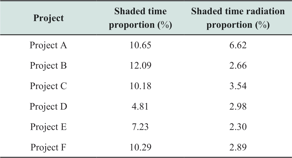
Table 2 Shading reduction factor of the four rows of lateral arrangement single row wiring PV array on Dec.21

Table 3 Shading reduction factor of the two rows vertical arrangement of ring-shaped PV array on December 21

As shown in the table,the shading duration of the front row shadows of the six PV power stations accounts for 4.81%–12.09% of the total sunshine duration of the year,and the corresponding solar radiation accounts for 2.30%–6.62% of the total annual solar radiation.The full use of this part of the solar radiation is very important for improving the power generation of PV power stations.
3 Operating mode of PV cell string units during the front-row shading period
The PV module is composed of PV cells.Using 72 PV modules as an example,each PV module includes 72 PV cells in six rows and 12 columns.The PV cells are connected in series,with 24 cells in series in every two rows.It is then connected in parallel with the anti-reverse diode to form a set of PV cell strings.Each PV module is composed of three PV cell string units in series,and the equivalent circuit of the PV module is shown in Fig.1:

Fig.1 Equivalent circuit of a PV module
The equivalent circuit model of a PV cell is shown in Fig.2 [10-16].
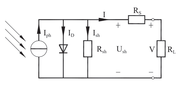
Fig.2 Equivalent circuit of a PV cell
When the surface of the PV cell array is uniformly illuminated,the short-circuit current(Isc)and operating current(Ipm)of the PV cell array are approximately linearly correlated with Irr of the irradiation intensity under different irradiation intensities,which is
When the surface of the PV cell string unit is under partial shading and the solar irradiance of the shaded cell surface decreases,the current in the cell decreases accordingly.Because all cells in the PV cell string are connected in series,the current of the PV cell string is equal to the current flowing in the cell with the lowest current.
(1)When the current in the string is less than or equal to the operating current of the cell with the lowest solar irradiance,the overall output power of the PV cell string is not affected by the shading.The greater the loop current,the greater the output power.
(2)When the current in the string is greater than the operating current of the cell with the lowest irradiation intensity,the overall output power of the PV cell string rapidly decreases to zero as the loop current increases.
(3)When the cell is under a shadow,the string current corresponding to the maximum string output power is approximately equal to the maximum operating current of the cell under the irradiance of the shaded area.
(4)When the PV cell string is not shaded,the maximum external output power of the PV cell remains basically the same under different shading ratios.The maximum output power of the battery string primarily depends on the irradiance ratio of the shaded and non-shaded areas,and the influence of the shading area ratio is negligible.
4 Calculation of solar irradiance during the front row shading
4.1 Division of the PV array into PV cell string units
The PV cell string is used as the basic unit to divide the PV array,which should be determined according to the layout and wiring of the PV array.Using the lateral arrangement single-row and the vertically arranged ring wiring modes as examples,an equivalent circuit model is established,and the PV cell string area is divided [17-20].
(1)Lateral arrangement and single-row wiring mode
If the PV array adopts a single row wiring mode,several PV modules in the same row are connected in series,and the negative pole of each module is connected to the positive pole of the adjacent module; the positive pole of the first module and the negative pole of the last module are respectively connected to the confluence equipment.
Only the span of the PV cell string unit in the direction of shadow movement on the surface of the PV array must be considered when dividing the PV cell string units of the PV array.When the PV array adopts a lateral arrangement and single-row wiring mode,the span of the PV cell-string unit is 1/3 of the width of the PV module.The equivalent circuit diagram is shown in Fig.3.
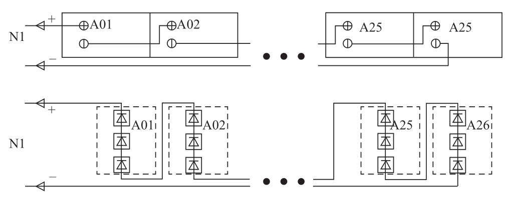
Fig.3 PV array division of lateral arrangement and single row wiring mode
(2)Vertical arrangement and ring-wiring mode If the PV array adopts a two rows ring wiring mode,the PV modules in the upper and lower rows are connected in series,and the negative pole of each module is connected to the positive pole of the adjacent module.The negative pole of the last module in the first row is connected to the positive pole of the last module in the second row,and the positive pole of the first module in the first row and the negative pole of the first module in the second row are connected to the confluence device.
When the PV array adopts a vertical arrangement and ring wiring mode,the span of the PV cell string unit is equal to the length of the PV module.The equivalent circuit diagram is shown in Fig.4.
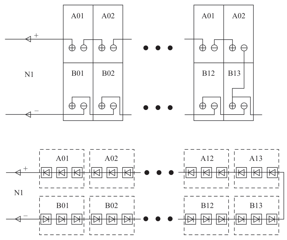
Fig.4 PV array division of vertical arrangement and ring wiring
4.2 Calculation of solar irradiance during front row shading
The surface of the PV array is divided by the azimuth angle of the PV array,and the PV cell string units are the smallest units.The solar altitude angle corresponding to the starting position of each PV cell string unit in the rear PV array when the shadow of the front row arrives is calculated according to the width of the PV cell string unit,the distance between the front and rear rows D,the inclination angle S of the PV array,the height difference H between the front and rear rows,and other parameters.
When the PV array adopts a four-row lateral arrangement and single-row wiring mode,the surface of the PV array is divided into 12 areas according to the PV cell string unit.When the front row shadow is at node A1,the front and rear rows of the PV array are at the critical point of shading; when the front row shadow is at node B2,there are a total of four PV cells string units A1,A2,A3,and B1 under shading.The relationship between the shaded area and the sun’s altitude angle is shown in Fig.5:
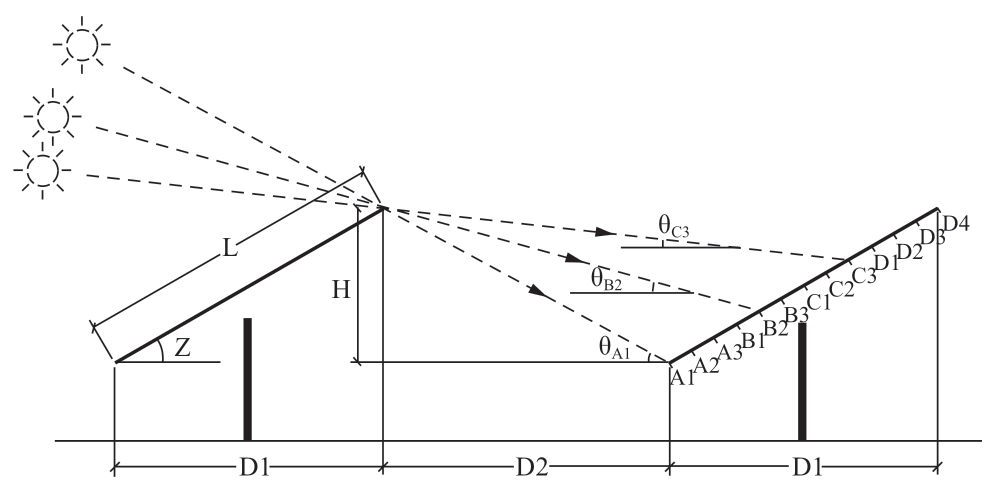
Fig.5 Surface area division of PV array with horizontal arrangement and single row wiring mode
When the PV array adopts two rows of vertically arranged and ring-shaped wiring modes,the surface of the PV array is divided into two areas according to the PV cellstring unit.When the front row shadow is at the node A1 position,the front and rear rows of the PV array are at the critical point of shading; when the front row shadow is at the node B1 position,the PV cells string unit A1 is under a shadow.The relationship between the shaded area and sun exposure angle is shown in Fig.6:
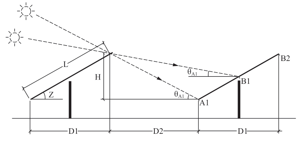
Fig.6 Surface area division of PV array with vertical arrangement and ring wiring mode
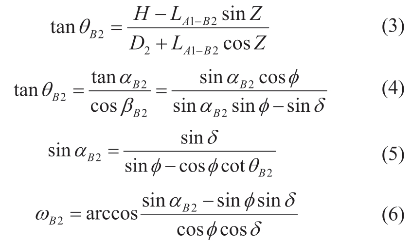
According to the relationship between the date(N),latitude(φ),solar altitude(α),solar declination(δ),and solar hour angle(ω),the solar hour angle can be calculated when the shadow is located at the corresponding node of the cell.
Using Fig.7 as an example,when the shadow of the front row is located at node B2,the four PV cell string units A1,A2,A3,and B1 are blocked.The span of the cell is calculated using the following formulae:

Fig.7 Correction coefficient of front row shadow occlusion loss and solar radiation of project A
By substituting the solar hour angle corresponding to each node into the Hay anisotropic sky scattering radiation model,the proportion of the solar radiation amount in each period in the solar radiation amount of the day can be calculated.Using the solar hour angle corresponding to the start and end times of shadow occlusion,the mean solar radiation intensity in the occlusion period can be calculated[8,12,13].

Ht:Total solar radiation
Hbt:Direct solar radiation
Hdt:Scatter solar radiation
Hrt:Reflection on solar radiation
Rb:Ratio of direct radiation from the inclined plane to horizontal plane.
![]() :Sunset angle
:Sunset angle
With![]() equal to ωB2 and using the above formula,the solar radiation amount of the inclined plane in this period can be calculated.
equal to ωB2 and using the above formula,the solar radiation amount of the inclined plane in this period can be calculated.
5 Calculation of the PV array system efficiency during the front row shading period
The output power of the PV array under shadow occlusion of the front row can be analyzed according to the shadow occlusion operating mode of the PV cell-string unit.The calculation formula is expressed as follows [21-27]:
Psha:Power of PV array when shaded
Nstr:Number of PV modules string
Nstr-un:Number of PV modules string unshaded
Nstr-sha:Number of PV modules string shaded
Nunit-un:Number of unshaded PV cell string units in a string with incomplete occlusion
The PV array system efficiency during the front-row shading period is calculated as follows:
(a)The basic parameters,such as latitude,date,direct irradiance ratio,PV array inclination angle,and array spacing are determined.
(b)The series and parallel modes of the PV cells and the layout and wiring modes of the PV arrays are determined.
(c)The PV array is divided into basic units according to the PV cell series.
(d)The solar altitude angle,solar azimuth angle and solar hour angle corresponding to each node are calculated.
(e)The total solar radiation,duration,direct radiation,and scattered radiation for each period are calculated.
(f)The solar radiation available for the PV array in each period is calculated.
(g)the loss coefficient of the shadow occlusion in the front row of the PV array is calculated.
Two examples are provided to illustrate the algorithm.
(1)Four rows of laterally arranged single-row wiring.
As illustrated by the example of four rows of laterally arranged single-row wiring(Fig.6),when the shadow of the front row is at the position of node B2,four PV cell string units A1,A2,A3,and B1 are under a shadow,and the remaining cell units are not shaded.There are three operating modes during this period.
(a)PV string A,where the cell units A1,A2,and A3 are all shaded,setting the output power of PV string A as P1;
(b)PV string C,where the cell units C1,C2,and C3 arenot shaded,setting the output power of the PV string C to P2.
(c)PV string B,where cell units B1,B2,and B3 are partly shaded,and when cell unit B1 is totally under a shadow,B2 and B3 are non-shaded.The number of shading cell units accounts for 1/3 of the PV string.The output power of PV string B is the largest among P1 and 1/3P2,that is,max {P1,1/3P2}.
The shading reduction factor of the PV array is calculated based on the solar irradiance,duration,ambient temperature,and operating mode of the PV string during the shading period.
The front row shading reduction of the PV array with four rows of lateral arrangement single-row wiring mode on Dec.21 is 73.93%.The amount of solar radiation corresponding to the shading period of the day is 6.610 MJ/m2.
(2)Two-row vertical arrangement of ring-shaped wires
As illustrated by the example of the two-row vertical arrangement of ring-shaped wiring(Fig.6),when the shadow of the front row is at node B1,cell unit A1 is covered,and cell unit B1 is not covered,then this period has two types of operating conditions:
(1)Cell unit A1,which is PV string A,is completely under a shadow,and the output power of PV string A is set to P1.
(2)Cell unit B1,which is PV string B,is not shaded,and the output power of PV string B is set to P2.
The shading reduction factor of the PV array is calculated based on the solar irradiance,duration,ambient temperature,and operating mode of the PV string during the shading period of the front row.
The front row shading reduction of the PV array with a two-row vertical arrangement and ring wiring mode on Dec 21 is 49.70%.The amount of solar radiation corresponding to the shading period of the day is 6.610 MJ/m2.
When different shading irradiance coefficients(the ratio of the amount of light radiation in the shaded area to that in the non-shaded area)are given in the above table,the efficiency of the various wiring modes during the shadingperiod compared with the non-shading period can be calculated.
The conclusions are as follows by comparison:
(a)During the front-row shading period,the output power of the PV array with a horizontal arrangement of the wiring scheme is higher than that of the vertical arrangement of the circular wiring.
(b)The main variable of the shading reduction coefficient is the ratio of solar irradiance P2 in the front-row shading period to the solar irradiance P1 in the non-shaded area.The larger the ratio,the less front-row shading affects the output power.As a result,the overall output power of the PV array is larger.
(c)When the modules are under the shadow of the front row array,the shorter the span of the cell string unit in the azimuth axis direction,the less the number of cell strings affected by the front row shadow.As a result,the overall output power of the PV array is higher.
6 Engineering case application
(1)Technical scheme of actual engineering case
Large-scale PV power stations frequently adopt a technical scheme with the most economical plan to satisfy the requirements of the technical specifications.Consider project A as an example.
(a)PV module with 72 crystal silicon modules
(b)Vertical layout mode
(c)Ring-wiring mode
(d)The azimuth of the PV array is 0°(due south),and the horizontal inclination is the optimum dip angle.
(e)The distance between the front and rear rows of the PV array is selected according to 15:00 of the winter solstice.
(2)Correction coefficient of front-row shadow occlusion loss
Using the calculation method of the correction coefficient of the front-row shadow occlusion loss proposed in this paper,the above conventional technical scheme can be optimized,and the optimized lifting effect can be accurately achieved.
We selected two project sites with the largest differences in the proportion of direct solar radiation.To facilitate the comparison process,we changed only one parameter for each comparison,whereas the other technical principles remain unchanged.
(a)PV module type
The PV modules were changed from 72 silicon modules to 144 half-wafer silicon modules.The 144 half-wafer silicon module included 144 half cells,each 24 half cells were connected in series into a group of cell group series cells.The entire PV module consisted of two rows and three columns,for a total of six groups of cell group series cells.
(b)PV array layout
The layout of the PV array was changed from two vertical to four horizontal rows.
(c)PV array wiring mode
The wiring mode of the PV array was changed from two rows ring wiring mode to a single-row wiring mode.
(d)Spacing of PV arrays
The horizontal inclination angle remained unchanged,and only the space between the front and rear rows was enlarged.
(3)In contrast to the conclusions of Project A
The geographical latitude of Project A was N29.65°,and the average annual horizontal solar radiation was 7251 MJ/m2,of which the direct horizontal solar radiation was 68.74%.When the horizontal inclination angle was 33°,the solar radiation intensity on the inclined surface of the PV array reached a maximum of 8338.1 MJ/m2.
Based on the conventional scheme,we calculated the change of modules,change of layout,change of wiring mode,change of space between the front and rear rows,and correction coefficient of shading loss in the front row of PV system efficiency.The calculation results are shown in Table 4 [28-31]:
(4)In contrast to the conclusions of another project with different solar radiation
The latitude of Project B was N30.08°,and the average annual horizontal solar radiation was 4227 MJ/m2,of which the direct horizontal solar radiation was 44.57%.According to the conventional scheme,the change of components,change of layout,change of wiring mode,change of space between the front and rear rows,and correction coefficient of shading loss in the front row of PV system efficiency were calculated.The calculation results are shown in Table 5:
Table 4 Correction coefficient of front row shadow occlusion loss in project A

continue

Table 5 Correction coefficient of front row shadow occlusion loss in project B

7 Conclusions
This paper proposes a calculation method for the frontrow shading loss coefficient of PV system efficiency.The results of this paper are as follows.
(1)The front-row shading loss coefficient of PV system efficiency is related to factors such as latitude,date,directirradiance ratio,array inclination,front and rear row spacing,layout and wiring modes,ambient temperature,and inverter starting voltage.

Fig.8 Correction coefficient of front row shadow occlusion loss and solar radiation of project B
(2)The surface of the PV array is divided into PV cell strings connected in parallel with the same anti-reverse diode as a unit.When the PV array is shaded by the front row array,the span of the cell string unit in the azimuth axis direction is shorter,and the number of cell strings affected by the front row shadow is lower.As a result,the total output power of the PV array is higher.
(3)The calculation method of the front-row shading loss coefficient can be used to evaluate the specific impact of the PV array inclination,the spacing between the front and rear rows,and the influence of the layout and wiring modes on the system efficiency,which is useful and meaningful for optimizing technical solutions,thereby aiding to reduce system losses and improve power generation efficiency.
(4)The main variable of the shading reduction coefficient is the ratio of the solar irradiance in the shaded area to the solar irradiance in the non-shaded area during the frontrow shading period.The lower the proportion of direct solar irradiance in the total irradiance,the less the influence of the front-row shading on the solar irradiance.Consequently,the overall output power of the PV array increases.
The calculation method of the front row shadow occlusion loss correction coefficient can be used to evaluate the influence of the PV module type,array layout,array wiring,and spacing on system efficiency,and for optimizing the angle of the PV array and operation mode,selecting bifacial components,analyzing PV modules below ground illumination time,and precisely evaluating solar radiation intensity.This method also provides important reference values for tasks such as optimizing technical solutions,reducing system loss,increasing the efficiency of power systems,and conducting agricultural,livestock,and composite complementary solar power station projects.
Acknowledgements
This work was supported by the Global Energy Interconnection Group Limited Science & Technology Project(Project No.:SGGEIG00JYJS1900046).
Declaration of Competing Interest
We declare that we have no conflict of interest.
References
[1] Chinese renewable energy industries association(2002)Present status and future potential of solar PV development in China.Renewable Energy,3:5-8(in Chinese)
[2] Peña R,Algora C(2003)Evaluation of mismatch and nonuniform illumination losses in monolithically series-connected GaAs photovoltaic converters.Progress in Photovoltaics:Research and Applications,11(2):139-150
[3] Wang Y,Hsu P(2010)Analytical modeling of partial shading and different orientation of photovoltaic modules.IET Renewable Power Generation,4(3):272-282
[4] Villalva M G,Gazoli J R,Filho E R(2009)Comprehensive approach to modeling and simulation of photovoltaic arrays.IEEE Transactions on Power Electronics,24(5):1198-1208
[5] Qi J,Zhang X,Zhang Y,et al.(2012)Study on simulation algorithm of PV array considering shade effect.Proceedings of the Chinese Society for Electrical Engineering,32(15):131-138
[6] Xie L,Sun Y,Li X,et al.(2013)The performance analysis of gird-connected PV system with some typical shading effects.Acta scientiarum Naturalium Universitatis Sunyatseni,52(6):129-132
[7] Zhou L,Liu Y,Lei T,et al.(2012)Study on the influence of intermittent shielding on power generation of PV module.Modern Electric Power,29(1):65-71
[8] Code for design of photovoltaic power station(for advice),GB 50797-20XX,37-39(in Chinese)
[9] He J,Hou S,Meng X,et al.(2020)Empirical data analysis of different PV array spacing.Solar Energy,3:51-56
[10] Wang M,Zhao R(2012)Practicable approaches to predicting PV array model parameters and I-U characteristics based on datasheet,30(3):102-107
[11] Liu Z,Lin L,Wang Y,et al.(2000)The open-circuit voltage of crystalline silicon solar cells under weak illumination.Acta Energiae Solaris Sinica,21(3):317-320
[12] Hay J E(1993)Calculating solar radiation for inclined surfaces:Practical approaches.Renewable Energy,3(4-5):373-380
[13] Yang J,Mao J,Chen Z(2002)Calculation of solar radiation on variously oriented tilted surface and optimum tilt angle.Journal of Shanghai Jiaotong University,36(7):1032-1036
[14] Li R,Yan Y,Hu B(2014)Reconfigurable optimization arrangement method of photovoltaic arrays in partial shade condition.Power System and Clean Energy,30(7):38-44
[15] Feng B,Su J(2011)Research on model and simulation of PV module under partially shaded conditions.Electric Drive,41(7):61-64
[16] Chai Y,Tong Y,Jin X(2013)Simulation study of PV modules under partial shading.East China Electric Power,41(2):376-379
[17] Ishaque K,Salam Z,Syafaruddin(2011)A comprehensive MATLAB Simulink PV system simulator with partial shading capability based on two-diode model.Solar Energy,85(9):2217-2227
[18] Villalva M G,Gazoli J R,Filho E R(2009)Comprehensive approach to modeling and simulation of photovoltaic arrays.IEEE Transactions on Power Electronics,24(5):1198-1208
[19] Li X(2019)Simulation and experiment study on output characteristics of roof photovoltaic array under shadow shading.Energy and Energy Conservation,3:64-65
[20] Xiao W,Yu X,Zhang H,et al.(2019)Comparative study of photovoltaic power generation math model under partial shading conditions.Electrical Measurement & Instrumentation,56(10):56-61
[21] Peña R,Algora C(2003)Evaluation of mismatch and nonuniform illumination losses in monolithically series-connected GaAs photovoltaic converters.Progress in Photovoltaics:Research and Applications,11(2):139-150
[22] Mäki A,Valkealahti S(2012)Power losses in long string and parallel-connected short strings of series-connected silicon-based photovoltaic modules due to partial shading conditions.IEEE Transactions on Energy Conversion,27(1):173-183
[23] Paraskevadaki E V,Papathanassiou S A(2011)Evaluation of MPP voltage and power of mc-Si PV modules in partial shading conditions.IEEE Transactions on Energy Conversion,26(3):923-932
[24] Quaschning V,Hanitsch R(1996)Numerical simulation of current-voltage characteristics of photovoltaic systems with shaded solar cells.Solar Energy,56(6):513-520
[25] Wang L,Wei X,Meng Y,et al.(2017)MPPT of PV array under partial shading conditions based on mutative scale chaos optimizing search.Journal of Central South University(Science and Technology),48(7):1790-1796
[26] Qi J,Ye B,Li Y,et al.(2020)A simplified simulation method for PV array’s output characteristics based on shadow recognition.Chinese High Technology Letters,30(2):185-195
[27] Tang Q,Zhu Y,Hao J(2018)Shadow diagnosis and localization of PV array based on optimal sensor collocation.Acta Energiae Solaris Sinica,39(2):513-519
[28] Tossa A K,Soro Y M,Azoumah Y,et al.(2014)A new approach to estimate the performance and energy productivity of photovoltaic modules in real operating conditions.Solar Energy,110:543-560
[29] Miyatake M,Veerachary M,Toriumi F,et al.(2011)Maximum power point tracking of multiple photovoltaic arrays:A PSO approach.IEEE Transactions on Aerospace and Electronic Systems,47(1):367-380
[30] Elobaid L M,Abdelsalam A K,Zakzouk E E(2015)Artificial neural network-based photovoltaic maximum power point tracking techniques:A survey.IET Renewable Power Generation,9(8):1043-1063
[31] Ning Y,Zheng J,Xia L,et al.(2015)Research and analysis on comprehensive output characteristics of photovoltaic power stations.Acta Energiae Solaris Sinica,36(5):1197-1205
Biographies

Bin Hu received bachelor degree at North China Electrical Power University,Beijing,2004.He received master degree at North China Electrical Power University,Beijing,2007.He is working in State Nuclear Electric Power Planning Design & Research Institute Co.,Ltd.,Beijing.His research interests include planning,design,research,operation analysis and evaluation of renewable energy power stations.

Jiawei Wu(Corresponding author),received Bachelor and PhD degrees in electrical engineering at Xi’an Jiaotong University,Xi’an,2012 and 2018 year.She is working GEIDCO,Beijing,China.Her research interests include renewable energy resource assessment and renewable energy power generation technologies.

Peng Li received Master degrees in electrical engineering at Beihang University,Beijing,2007 year.He is working GEIDCO,Beijing,China.His research interests include is power electronics,renewable energy resource assessment,power system planning and reactive power compensation.

Wei Sun received Bachelor and PhD degrees in electrical engineering at China University of Mining and Technology,Xuzhou,2004 and 2009 year.She is working at GEIDCO,Beijing,China.Her research interests include wind turbine modelling,renewable energy gird integration analysis,control and modeling of DC grid,economic and technical forecasting of renewable energy power generation technologies,renewable energy resource assessment.

Jinyu Xiao received Bachelor and PhD degrees in electrical engineering at Tsinghua University,Beijing,1999 and 2005 year.He is working GEIDCO,Beijing,China.His research interests include electrical system planning and novel energy technologies.
(Editor Yajun Zou)
