0 Introduction
As the demand for renewable energy continues to increase,power electronic devices will permeate future power systems,which are referred to as “double high”systems.The traditional synchronization mode of power systems dominated by synchronous generators is broken,and the stability mechanism also changes.Table 1 compares the traditional grid with the “double high” grid.When the proportion of new energy power generation exceeds 50%,the frequency of the entire system undergoes a fundamental change [1].This change is mostly a result of the low inertia of the non-synchronized unit,which leads to large fluctuations in the system frequency when the load changes and the adjustment level is significantly reduced.The synchronous generator has a rotating mechanical rotor that stores the “spare power” of the system.Therefore,when the grid-side power demand changes,the moment of inertia of the rotor can be used to balance the system power change [2-4].Because the power supply of a nonsynchronous machine does not have the function of “energy storage” with respect to the rotor,the functions of power balance and power synchronization in the system will be realized through the control strategy associated with its power electronic device.However,at present,photovoltaic and wind power are connected to the grid by grid-following(GFL) converters,which are not applicable to a weak grid,thus,the concept of grid-forming control (GFM) has been proposed [5,6].
The GFL and GFM controls are applied individually to strong and weak power grids.At present,the GFL converter is a current source,as shown in Fig.1(a),which is connected to the power grid and synchronized with the power grid through a phase-locked loop (PLL).Although GFL exhibits better stability than GFM under a strong power grid,it can only follow the voltage and frequency of the power grid and cannot actively control its frequency output.In addition,GFL cannot provide inertia for the system and even reduces the strength of the system,which limits its utility in future power systems with a high number of power electronic devices [7,8].References [9-11]show that as the penetration level of power electronic devices increases,damping of the GFL converter decreasesand the frequency shift is large,thereby increasing the system’s sensitivity to inertia.Compared with GFL,GFM can act as a voltage source,as shown in Fig.1(b),so it can independently establish voltage and frequency through corresponding control strategies,increase system damping,reduce frequency offsetting,improve system stability,and reduce the dependence on the system’s mechanical inertia.In future “double high” power systems,denoting a high proportion of renewable energy and a high proportion of power electronic devices,GFM converters are more practical than GFL converters in such a weak power grid.Table 2 presents a comparison of GFL and GFM converters.
Table 1 Comparison between traditional grid and grid
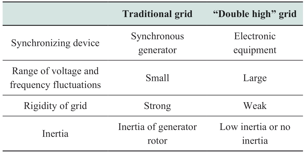
Table 2 Comparison between GFL and GFM converters

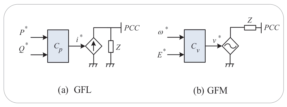
Fig.1 Simplified representation of GFL and GFM converters
Regarding the voltage source characteristic of GFM,the control strategy,which can independently establish voltage phasors to provide inertia for the system,is the most important part of GFM for realizing the function of“forming a grid”.Therefore,in this review,we analyze and summarize such GFM control strategies,which are divided into droop control,power synchronization control(PSC),virtual synchronous machine control (VSC),direct power control (DPC),and virtual oscillator control (VOC).These five strategies can independently be used to establish voltage phasors.Finally,the key technologies and future research directions for GFM control are discussed.
1 Brief introduction to GFM control
At present,the precise definition of a GFM converter is still under investigation.In this review,GFM generally refers to a converter that adopts GFM control without relying on grid-side synchronous generator adjustment so that the AC power system can operate under normal,interference,and emergency conditions.When the GFM is normally connected to the grid,it is externally displayed as a voltage source mode.When it is operating on an island,it can still reliably supply power to the local load.
Fig.2 shows the block diagram of the GFM control.The GFM converter uses hierarchical cascade control to regulate various parameters,including the inner and outer loops.The output voltage amplitude and phase angle of each control strategy are provided to the inner loop controller,and the PWM signal is generated through coordinate transformation.Essentially,the inner loop strategies are the same,and the difference is primarily reflected in the outer loop.
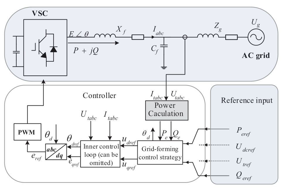
Fig.2 Block of GFM control
For the outer loop,the DC-side voltage Udcref or the ACside active power Peref is used as the active power reference input,and the AC-side reactive power Qeref or the grid-side voltage Utref is used as the reactive power reference input.The voltage reference value and phase angle are output to the inner-loop controller through the GFM control strategy.The outer power loop is discussed further in Section 2.
The inner loop can use current control,or voltage and current double-closed-loop control.Alternatively,the innerloop control can be omitted and the voltage signal can be directly synthesized into a PWM modulation signal,similar to the situation in which the outer loop uses DPC.Fig.3 shows a typical loop,where the inputs are Vd and θd from the outer power loop.Through voltage and current control,and then by coordinate transformation,the PWM modulation signal is obtained.The rational design of the PI controller parameters can configure the bandwidth of the voltage and current control loops within a certain range.This design can improve the dynamic response performance of the voltage and current output and limit the fault current.
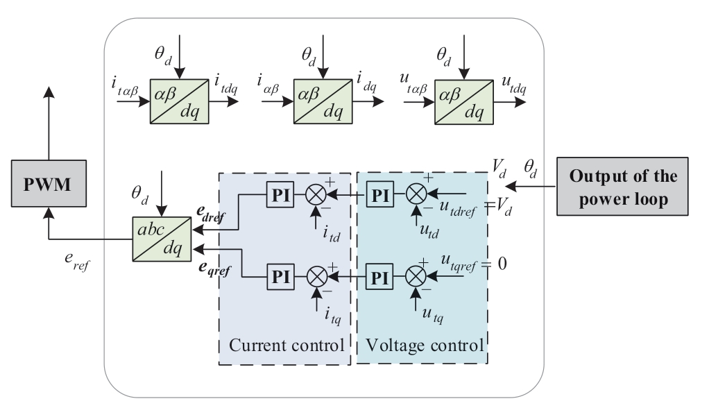
Fig.3 Inner control loops of GFM control
2 Control strategies for GFM control
Simulating the performance of synchronous generators is the most direct and effective method to achieve GFM control.Therefore,GFM control primarily simulates the relevant characteristics of a synchronous machine,so that the power electronic device can have adjustment and analysis methods that are similar to those of a synchronous machine.Based on various characteristics,simulating the generator can obtain the corresponding GFM control strategy.Synchronous generators have P/f and Q/V droop curves,where the simulation droop control occurs.Moreover,the synchronous generator model includes characteristics such as mechanical motion,electromechanical transients,and electromagnetic transients,based on which the PSC,VSM,and DPC are obtained.In contrast,VOC is a nonlinear control method that uses an oscillator circuit to realize synchronization.Each of these strategies is described below.
2.1 Droop control
2.1.1 Introduction and improvement of droop control
Droop control,which simulates the P/f and Q/V droop characteristics of traditional synchronous generators,is one of the most widely used methods of GFM control and is simple to implement.Ideally,power can be distributed in proportion to a specific droop coefficient without communication.For long-distance lines,the communication lines are reduced,thereby reducing costs [12-15]; plug and play,which is convenient for system expansion,reduces the complexity of the system and improves the reliability of the system [16-20].
A traditional droop-control block diagram is shown in Fig.4(a).However,traditional droop technology has many disadvantages; for instance,when the line impedance between the parallel converters is not matched,circulation between the converters affects the sharing of active and reactive power.As the droop increases,so does the load sharing accuracy,but at the same time,the voltage regulation deviation is large; and based on the droop characteristics of the fundamental wave equivalent circuit,the harmonic circulation generated when a non-linear load is applied leads to poor power quality and a slow dynamic response [21-23].
In the case of strong line impedance,the coupling between the active power and reactive power is strong,and traditional droop control cannot achieve a balanced power distribution among parallel converters,which affects the performance of droop control.Reference [24]increased the virtual impedance loop and realized a reasonable distribution of reactive power using a fast control loop of virtual impedance to improve the system response characteristics,as shown in Fig.4(b).However,this method leads to a decrease in voltage regulation performance and an increase in open-circuit voltage.Therefore,based on the virtual impedance control loop,reference [25]proposed a droop control that combines virtual impedance with a virtual synchronous machine to reduce the converter output voltage deviation; reference [26]proposed an amplitude correction method to reduce the converter output voltage deviation.
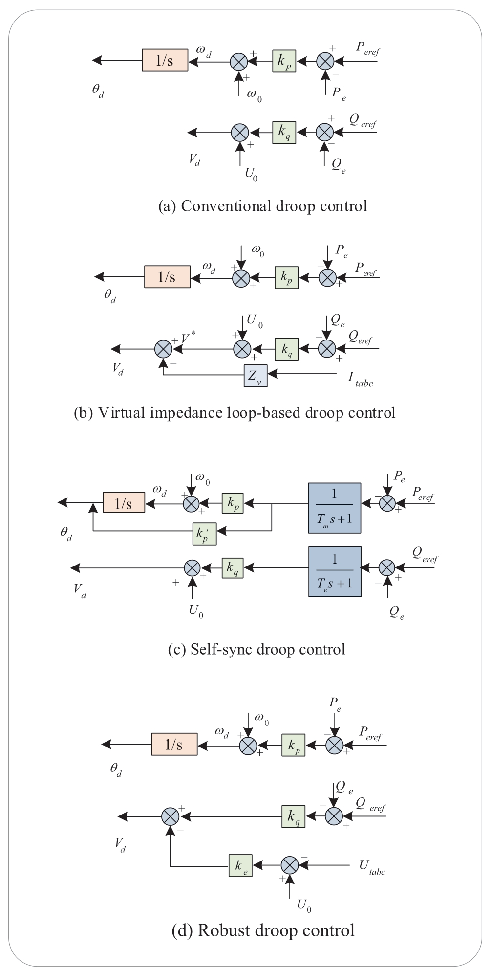
Fig.4 Droop control
In references [27,28],adaptive droop control was proposed to achieve a reasonable distribution of reactive power while maintaining the voltage amplitude.The adaptive droop control takes the difference between the output reactive power and reactive power reference as an additional quantity of the output voltage reference value.The constant and differential terms of the power enable the droop coefficient to be adjusted adaptively as the power changes.However,this method is more complicated to control,and its active power-sharing ability is weak.
References [29,30]proposed self-synchronous droop control,as shown in Fig.4(c).The output power passes through a low-pass filter to reduce the power oscillation caused by the harmonic factor,and an angle feedforward is added to the active power loop to increase the forward damping and improve the system stability and dynamic response capability,which can be found in reference [30].In addition to the time constant,these parameter values are the unit values of the rated power and rated voltage of the converter,so various rated power and voltage levels can be easily controlled.Reference [31]proposed robust droop control,as shown in Fig.4(d).The droop equation is corrected by subtracting the value of the converter output voltage,which compensates for the voltage drop caused by the voltage drop and load effects.When the output impedance of each converter is different or the voltage set value is different,accurate proportional load sharing can be realized,and the voltage drop caused by the load effect and droop effect can be reduced.However,this control weakens the reactive power sharing ability and increases the harmonic component of the current.
2.1.2 Research direction of droop control
Based on the overall discussion of droop control,some issues still need to be resolved:
• Stability: under complex loads,existing droop control strategies cannot achieve system stability [32].Therefore,the voltage,frequency,and power angle must be solved for droop-control strategies.
• Poor performance with the integration of renewable resources: some renewable resources exhibit poor performance with droop control methods; this problem should be solved with further research.
• Heavy influence of the condition of the line and the strength of the connected grid: a universal droop control method must be identified to solve this problem.
2.2 Power synchronization control
2.2.1 Introduction and improvement of power synchronization control
Power synchronization control (PSC) is a control strategy that simulates the mechanical motion equation of a synchronous generator and uses a power synchronous loop (PSL) to replace the phase-locked loop (PLL).The converter has the function of self-synchronization by analogy with the characteristic that synchronous motors maintain synchronization through a change in active power[33].When the PLL is adopted,the DC-side power of the converter is affected by the PLL parameters and system short-circuit ratio,which deteriorates the dynamic response performance of the system when the system strength is reduced.The use of PSL can avoid the instability caused by PLL when the converter is connected to a weak AC system with high impedance and low inertia,reduce the use of synchronous capacitors,and reduce investment and maintenance costs [33-37].Currently,this technology is primarily used in HVDC systems.
The PSC block diagram is shown in Fig.5(a).The output of the PSL control loop is θd; thus,the PLL is replaced to effectively prevent the influence of the PLL on control performance when connected with a weak network.At the same time,the introduced damping coefficient causes the converter to play the role of inertial support for the AC system.The voltage regulation circuit is similar to the excitation regulator of a synchronous motor,which can provide voltage support for a weak AC system as a synchronous generator.
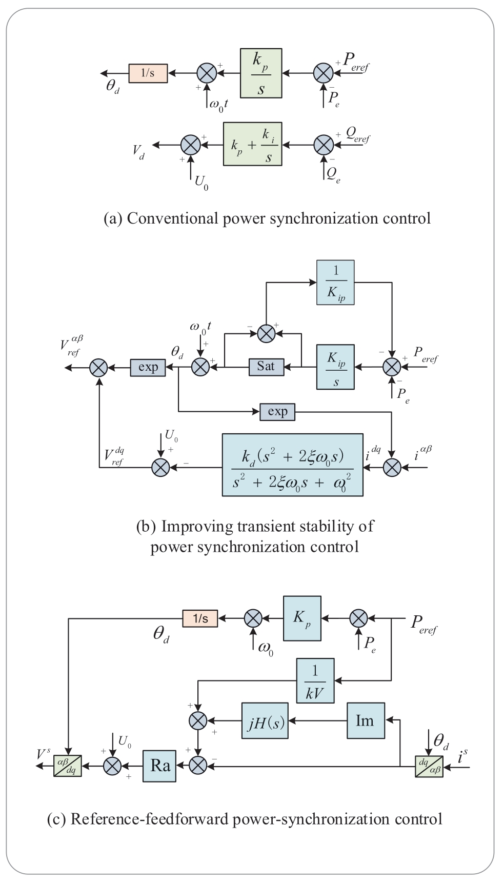
Fig.5 Power synchronization control
Reference [38]conducted further research on power synchronization control.The modeling and simulation of a general island system shows that the PSC is flexible,can seamlessly handle the transition between operation modes,and has a significant fault ride-through capability.References [39,40]analyzed the small-signal stability of a PSC converter through the Jacobi transfer matrix and impedance model.The results show that the power synchronous control exhibits strong small-signal characteristics in a weak network.Reference [41]designed a transient performance research method for PSC.The results show that,after transient interference,it can still resynchronize with the power grid after approximately one cycle of oscillation to reduce the risk of system collapse caused by delayed fault clearing.Based on the transient analysis,a previous study [42]proposed an improved transient stability control structure,as shown in Fig.5(b).A modified active power error expression and DC current component suppression are introduced to enhance the transient stability of the system,facilitate power transmission,and improve the self-synchronization ability after a fault.
Reference [43]combined virtual impedance technology with PSC.The voltage and phase angle information output by the power loop control are sent to the current control through a virtual impedance loop.Using virtual impedance technology,the circulating current between parallel converters is reduced and the power quality is improved.In addition,the virtual impedance transfer function is added to change the active power loop to a second-order loop so that it can adjust the DC-side voltage and damping coefficient,which effectively improves the dynamic characteristics of the system.Reference [43]showed that PSC is similar to droop control and reflects the droop characteristics of P/f. However,in the voltage-control circuit,because of the reduction in voltage amplitude caused by the reactive current,there is a negative gain opposite to the Q/V droop in the voltage-control circuit.Based on the PSC,the inner current loop added in reference [5]includes a circulating current suppression control loop that can effectively suppress the internal circulating current.
Because the closed-loop bandwidth of PSC is inherently limited and the step response usually shows an overshoot,a reference feedforward PSC has been designed,as shown in Fig.5(c) [44],which feedforwards the power reference to the active resistance part,so that the zero point of the closed-loop system can eliminate a complex pole point pair to reduce the system order from 3 to 1.Zero-pole cancellation occurs,regardless of the power grid inductance,to ensure the robustness of the system.
2.2.2 Research direction of PSC
Based on the overall discussion on PSC,there are still some issues that need to be resolved:
• Versatility of other scenarios: currently,PSC is mostly used in HVDC systems.Therefore,when used in other scenarios,such as island systems,the dynamic response and the issue of stability still need to be studied.
• Compatibility with other control strategies: PSC utilizes an internal synchronization mechanism in an AC system,similar to the operation of a synchronous machine.Thus,the compatibility of PSC with other control methods in a system and the role that PSC can play in this system should be investigated.
2.3 Virtual synchronous machine control
2.3.1 Introduction and improvement of Virtual synchronous machine control
A virtual synchronous machine (VSM) is a control strategy that directly simulates the internal and external characteristics of synchronous machines using a mathematical model of synchronous machines and introducing rotor motion and electromagnetic transient equations.Through VSM technology,the converter can be made equivalent to a synchronous machine,and similar moment of inertia and damping characteristics can be simulated.With VSM control,the converter can be considered equivalent to a synchronous machine and integrated into an AC system; thus,it has independent active power-frequency regulation control,independent reactive power-voltage regulation control,virtual inertia control,and damping control with respect to the synchronous unit.When the grid operation condition changes,the converter responds accordingly to grid operation problems [45],and VSM control can realize the consistency and compatibility of system analysis and reduce system complexity and computation.At present,virtual VSM technology is mature and can be flexibly used in wind power generation,solar power generation,static VAR compensators,and machine speed regulation.It has also been applied to largescale renewable energy power generation projects,such as the demonstration project of the Zhangbei storage and transmission base of the State Grid [46,47].
VISMA [48]was an early implementation of VSM.It uses the traditional mathematical model of a synchronous machine to calculate the current reference value of the converter and then controls the power.It can imitate a traditional synchronous machine to provide virtual inertia and damping for the system; however,it shows the characteristics of a controlled current source,which is incompatible with the current power system dominated by a voltage source.This also threatens the stability of the system [49,50].On this basis,reference [45]proposed the concept of a synchronous converter.As shown in Fig.6(a),in contrast to the current reference value output by VISMA,the synchronous converter uses the mathematical model of the synchronizer to generate the output voltage command for the converter to control the output voltage of the converter.In this implementation,the virtual mass inertia damping is realized only by the feedback of the difference between the VSM output frequency and the frequency reference;therefore,it also reflects the P/f droop characteristics.However,because the early synchronous converter requires a synchronization unit (such as a PLL) to provide grid information,to avoid the instability of the PLL and to reduce the system stability and system complexity,the concept of self-synchronized converters has been proposed in the literature [51,52],as shown in Fig.6(b).The selfsynchronization performance of the synchronous converter can be improved by removing the special synchronization unit.The self-synchronous converter synchronizes with the grid through an internal control algorithm before the grid connection and tracks the grid frequency after connecting to it.The synchronization performance is improved,and the complexity and computation of the controller are reduced.
However,while simulating the operation performance of synchronous machines,their high fault current will also be copied,resulting in an excessive current rating for converter devices.In the case of a fault,it is necessary to switch to the current source control mode,which cannot bear the performance of “grid-forming”.Reference [53]proposed a VSM control method with a virtual resistance that can reduce the fault current while maintaining the network function.In reference [54],addressing the issue of poor transient stability of a GFM converter controlled by VSM,a hybrid synchronous control was proposed,which combines the swing equation of a traditional synchronous machine and a PLL to improve its transient stability margin.
For the damping design of the control system,reference[55]proposed an effective damping method to improve the response performance of the converter,providing two adjustable parameters that can flexibly adjust the system damping without affecting the inertial response.Reference[56]provides a design method for virtual synchronous control parameters that can improve the speed of calculating control parameters,balance power pulsation,and maintain the stability of the system without affecting its dynamic performance.Reference [57]introduced a cooperative adaptive control strategy for inertia and damping coefficients to improve the dynamic response ability of the converter.Reference [58]added a damping correction auxiliary loop based on traditional VSM control,which can freely adjust the dynamic response speed.An adjustable parameter was set in the auxiliary loop to allow the system damping ratio to be adjusted without affecting the steadystate frequency response characteristics.
To improve the control performance of the converter,droop control can be added to the active control and reactive control loop to realize primary frequency modulation and primary voltage regulation functions similar to the synchronous machine,so as to obtain VSM control with primary frequency modulation and primary voltage regulation functions,as shown in Fig.6(c).
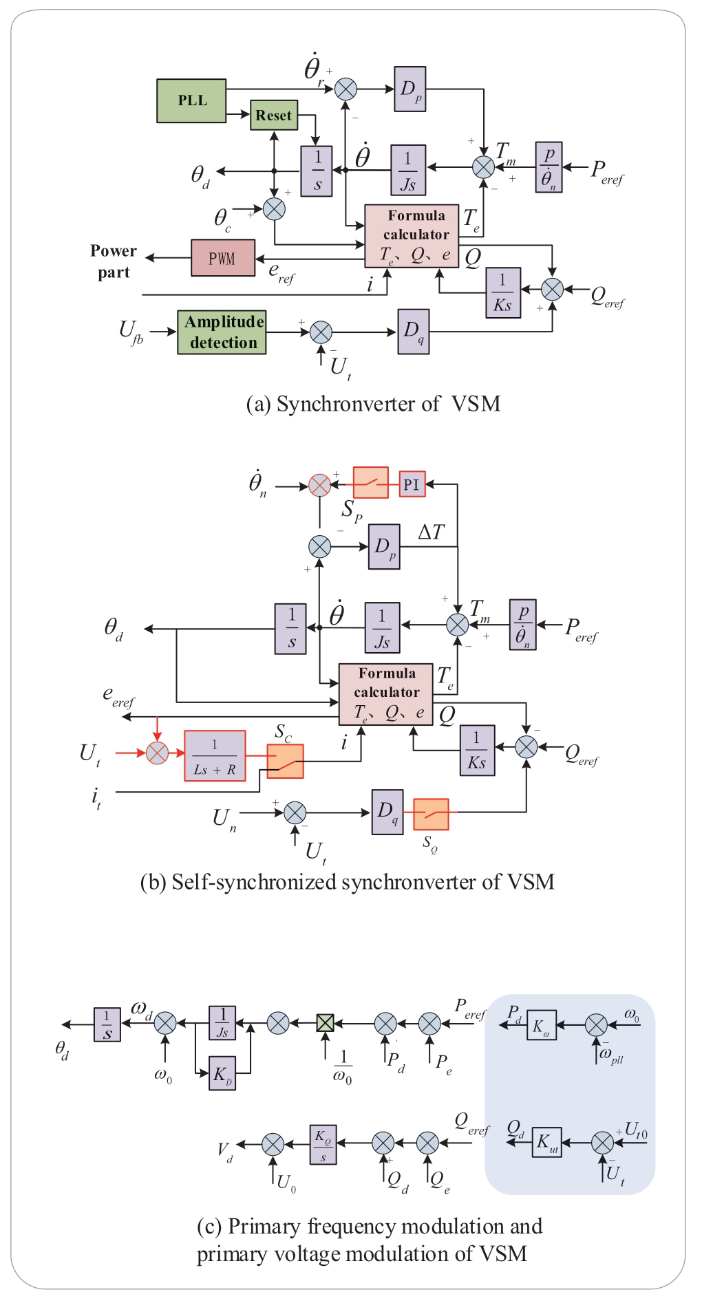
Fig.6 Virtual synchronous machine control
2.3.2 Research direction of VSM
Based on the overall discussion of VSM,some issues still need to be resolved:
• Mechanism of parallel operation with several VSMs:compared with droop control,the current-sharing speed of multiple VSM units slows down,so the current-sharing mechanism and fast power-sharing control strategy between multiple VSMs need to be further studied.
• Safe regulation area and fault ride-through capability:in the process of frequency modulation and voltage regulation,excessive impulse current may endanger the safety of power devices.Therefore,the safe regulation area and fault ride-through capability of VSM also need to be studied further.
2.4 Direct power control
2.4.1 Introduction and improvement of direct power control
In contrast to droop control,PSC,and VSM,direct power control (DPC) is based on AC motor direct torque control [59],which can use the error between the actual power and a reference value to control the active and reactive powers of the converter [60-62].Therefore,a current inner control loop does not exist in the DPC.The structure of the control system is simpler because the Park coordinate transformation and inner current controller are no longer needed.It has been used in converters,particularly in doubly fed induction generators (DFIG).
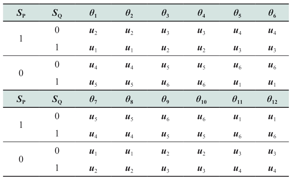
The conventional DPC,referred to as a look-up-table DPC (LTU-DPC),utilizes the switching table shown in Table 3 to choose the switching signals.The hysteresis regulator is adopted,and the output is obtained by the optimal voltage vector,which is chosen by the instantaneous errors of the active power and reactive power,as well as the phase angle of the terminal voltage of the converter.The LTU-DPC control system is shown in Fig.7(a).Although it has a simple control structure,the LTU-DPC changes its switching frequency with time.Pulses occur in power,and electromagnetic torque and extra harmonics are generated,which is not conducive to filter design.
Table 3 Switching table for LTU-DPC
For a constant switching frequency,the space-vector modulation DPC (SVM-DPC) control method was proposed in references [63]and [64].This method,which uses active and reactive power as the modulating signals for spacevector modulation (SVM),combines the advantages of SVM and DPC.A virtual flux estimator is utilized to replace the line voltage sensor,and a more affordable and technical operational mode is achieved.With simple algorithm logic,high dynamic speed,and constant switching frequency,the SVM-DPC simplifies the control system,and the system stability is improved with lower operating costs.However,the SVM-DPC requires the phase of the grid voltage and a complex coordinate conversion process.References [65-67]proposed a model-predictive-control DPC (MPC-DPC),where three voltage vectors are chosen in a control period to achieve minimum errors regarding the active power and reactive power and calculate the vector action time.MPCDPC can achieve less power fluctuation and a constant switching frequency with a simpler modulation algorithm.Nonetheless,selecting the voltage vector set and calculating the duty cycle in each sampling period require a large calculated capacity,and the control complexity is increased.An improved optimization algorithm was proposed in reference [68]to reduce the computation.Reference [69]proposed an improved model predictive control method for a high-power neutral point-clamped converter,where a low switching frequency can be achieved with a longer predictive period.
In references [70-72],a sliding-mode-DPC (SMCDPC) control method was proposed to boost the robustness of the control system.The sliding mode control (SMC)method,which is based on a variable structure control strategy,is a high-frequency switching control for nonlinear uncertain systems.The SMC has the advantages of a simple structure,high disturbance rejection performance,strong robustness,and fast dynamic speed by forcing the system to move up and down with a small amplitude.Meanwhile,the tracking errors of the active and reactive powers converge exponentially.However,the traditional SMC may not converge to the equilibrium point.To solve this problem,a novel port-controlled Hamiltonian DPC method was designed according to the inherent discrete characteristics of the system [73].Furthermore,a reduced-structure backstepping DPC was proposed in reference [74],which obtained good steady-state performance.However,there is a steady-state error when disturbances interfere with the system or the modeling is inaccurate.For better disturbance rejection performance,reference [75]utilized a virtual phase signal to transfer the coordinates.
Recently,a grid-voltage-modulated DPC (GVM-DPC)method with strong robustness,compact control structure,and low harmonic current output was proposed in references[76-78].The GVM-DPC uses a tracking controller that combines feedforward and PI feedback loops,as shown in Fig.7(b),to control the second-order error dynamics of active power and reactive power.This makes the system linear time-invariant.A fast rate of convergence and the stability of the closed-loop parameters of the system are guaranteed.
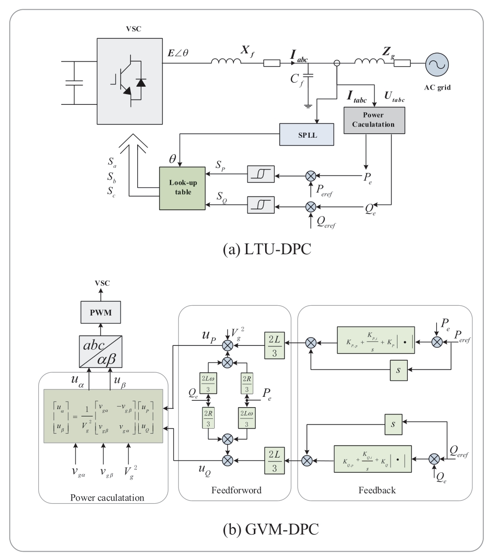
Fig.7 Power direct control
2.4.2 Research direction of DPC
Based on the overall discussion of DPC,some issues still need to be resolved:
• Improvement of DPC performance under low switching frequency: to achieve low harmonic distortion in currents,a very high sampling frequency is required.However,a high switching frequency sometimes has a negative effect on the unit,so improvement of the performance of the DPC under a low switching frequency should be further studied.
• Robustness performance,tracking performance,and steady-state performance of DPC when compared with other methods that are based on the mechanism of synchronous machines: DPC is quite different from other methods based on the mechanism of synchronous machines; therefore,the effect of the synchronization mechanism on the robustness performance,tracking performance,and steady-state performance is still worth studying.
2.5 Virtual oscillator control
2.5.1 Introduction and improvement of virtual oscillator control
Virtual oscillator control (VOC),a novel control method,has been proposed to output voltage phasors by simulating the dynamic properties of limit cycle oscillators,such as dead-zone oscillators and Van der Pol oscillators[79,80].This is in contrast to other controllers based on phasor representation.It is a sinusoidal time-domain implementation that uses only the output current of the converter as input and can respond to instantaneous current changes without voltage measurement,power calculation,or power filters.For practical applications,VOC has been adopted in single-phase and three-phase microgrids [81-83].
The structure of a conventional VOC is shown in Fig.8,where kv and ki are proportionality coefficients.The output current of the inverter is fed back to the VOC circuit,and the resonant frequency is set to ω* by varying the capacitance and inductance values.
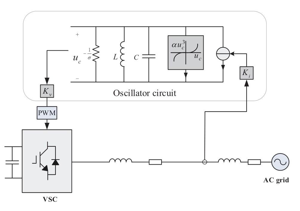
Fig.8 Virtual oscillator control
References [84-89]compared VOC with droop control,showing that VOC has a faster dynamic speed.When the frequency of VOC is sufficiently large,the time required to reach a stable state is shorter than that under droop control.With the expansion of the frequency regulation range,the advantages of VOC over droop control are more prominent,and the dynamics of the virtual oscillation loop are similar to the classical sinusoidal steady-state droop behavior.VOC enables precise power sharing when the output impedance of each converter is mismatched,while providing synchronization speeds much faster than that of droop control or VSM.
However,utilization of the traditional VOC has been limited because of the lack of effective compatibility between grid-connected and island operation technologies,and it also has the problem of third-harmonic voltage output.To solve this problem,a compatible layered control structure was proposed in reference [90]to operate and seamlessly switch between island and grid-connected modes.In island mode,the controller adjusts the voltage frequency.In gridconnected mode,the harmonic current is limited by the notch filter.Conversely,the notch filter also decreases the connection speed of multiple converters.A novel VOC based on the Andronov–Hopf oscillator (AH-VOC) was reported in references [91,92].AH-VOC is a secondorder non-linear system that can reduce the third-order harmonic of the converter output without affecting dynamic performance.Reference [93]optimized the nonlinear current source of a conventional oscillator.Compared with the traditional VOC,the response speed of the optimized VOC increased significantly.Compared with the traditional VOC with a notch filter,the new controller can suppress the third harmonics under various initial conditions when the system is operating in an island state.The synchronization speed will not be affected.Furthermore,reference [88]expounded on the comprehensive requirements of the “girdforming” function for converters with VOC.To realize smooth control of the active power and reactive power,an additional power loop was added in reference [94],and complex value parameters were introduced in reference[95]to realize independent control of the active power and reactive power.
2.5.2 Research direction of VOC
Because VOC is a novel control strategy,there are many aspects to be studied; only a few directions are given for reference:
• Expansion of application scenarios: currently,VOC is mostly used in single-phase and three-phase microgrids;thus,there is a wide range of other VOC scenarios to be explored.
• Robustness performance,tracking performance,and steady-state performance of VOC: like DPC,VOC is quite different from other methods based on the mechanism of synchronous machines; therefore,the effect of this difference on the robustness performance,tracking performance,and steady-state performance is worth studying.
3 Conclusion and outlook
In this study,we introduce the five control strategies that are the main strategies of the current constitutive GFM controls: droop control,power synchronization control(PSC),virtual synchronous machine control (VSM),direct power control (DPC),and virtual oscillator control (VOC).Droop control,PSC,and VSM are based on the analysis of the synchronous generator model,so that the GFM can have the corresponding synchronization machine characteristics.DPC,which controls active power and reactive power directly,does not require an inner current controller,and VOC is a sinusoidal time-domain implementation using oscillating circuits to achieve synchronization,which does not require voltage measurement and power calculation.A summary of GFM converters is presented in Table 4.
Table 4 Summary of GFM converters
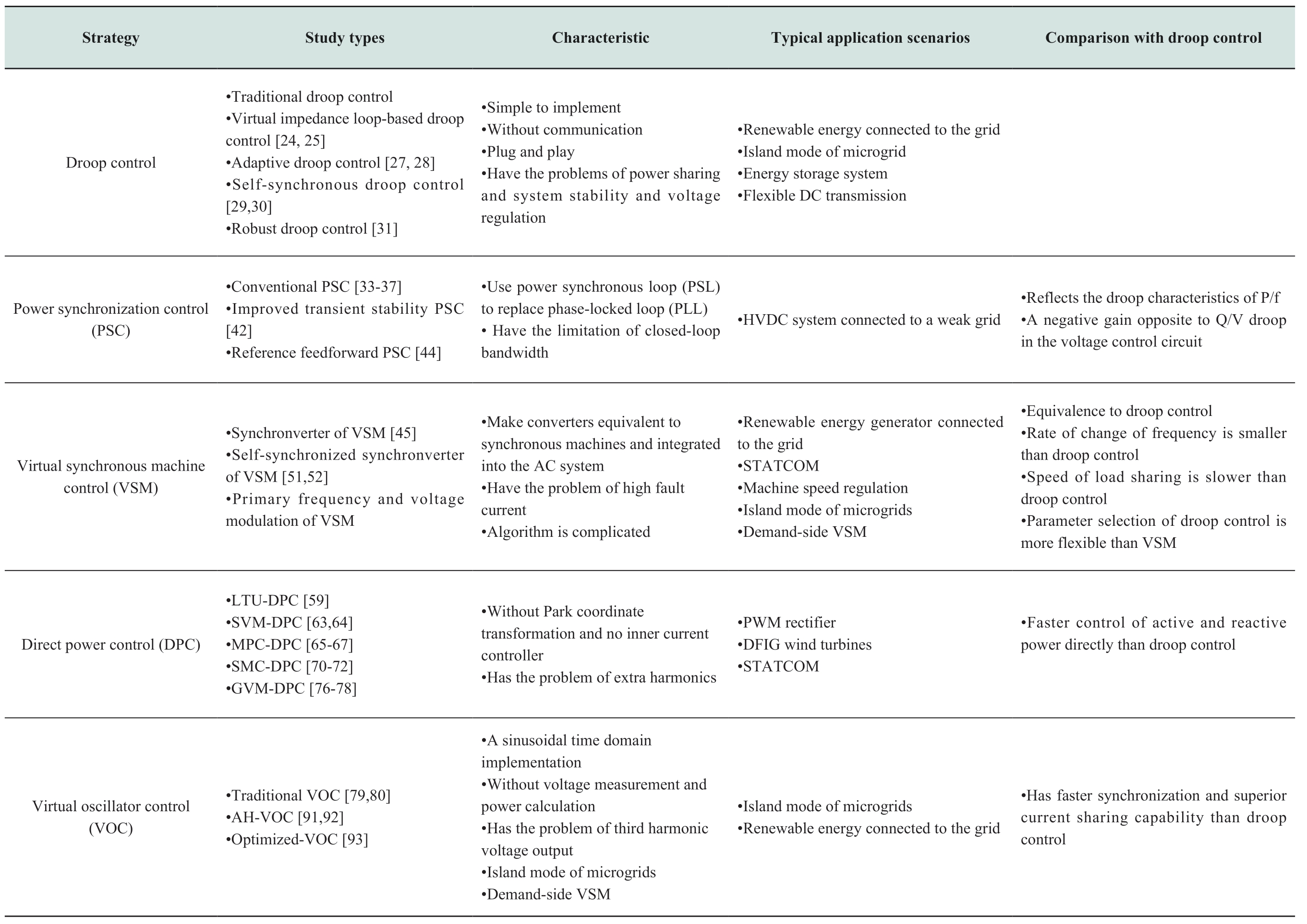
GFM converters can improve the strength of the system,reduce the fluctuations in voltage and frequency,and improve the stability of the system.Therefore,it has great potential in many scenarios.It can be used in island systems to improve the power quality,stability,and operating reliability.Similarly,in energy storage systems and connections to the grid of new energy sources,GFM converters can also be utilized to restrain power volatility and improve energy efficiency.Furthermore,with the increase in transmission capacity of flexible HVDC,it will properly participate in frequency modulation,which could be realized by GFM.The other conditions are listed in Table 4.
With the development of a “double high” power system,GFM converters will gradually be applied,which will meanwhile bring new opportunities and challenges:
• Coordinated control of multiple converters: the premise of cooperative control of large-scale converters is to realize global information sharing between converters,which requires the support of sensing and communication technologies.In addition,to operate more economically,partial converters can be selected as GFM controls in a system with a high proportion of power electronic devices;therefore,the selection and arrangement of GFMs for the system is an important topic that still deserves to be explored and studied.
• Overload capacity of GFM converters: the overload capacity of power electronic equipment is lower than that of conventional machines,which poses a challenge to the operation and protection of the power grid and requires further research.Conversely,the rapidity of power electronic equipment is much better than that of conventional machines; therefore,how to make full use of this advantage to improve the controllability of the power system,improve the response speed of protection,and reduce the requirements of overload capacity is worth further study.
• Synchronization stability: a GFM converter has better synchronization stability in a weak power grid than a GFL converter.However,when the power grid is strong,the GFM converter may lose synchronization with the power grid after a small disturbance.Therefore,when adjusting the parameters of the GFM converter,attention should be paid to maintaining the damping ratio within an appropriate range.A GFM converter may also exhibit a transient instability phenomenon similar to that of synchronous generators under large disturbances.Currently,regarding GFM control,the study of large disturbance synchronization stability is still in its infancy; it is worth further discussion.
• The theoretical system of a “double high” power system: the theoretical system can not only cause new energy and a large number of loads to have friendly access to the power grid,but also greatly improve the ability of the power grid to deal with faults and provide the possibility for the automatic decomposition and reorganization of the power grid.However,these issues require further study.
Acknowledgements
This work was supported by the National Natural Science Foundation of China (No.52177122),the“Transformational Technologies for Clean Energy and Demonstration”,Strategic Priority Research Program of the Chinese Academy of Sciences (No.XDA 21050100),and the Youth Innovation Promotion Association CAS(No.2018170).
Declaration of Competing Interest
We declare that we have no conflict of interest.
References
[1]Zhuo ZY,Zhang N,Xie XR,et al.(2021) Key technologies and developing challenges of power system with high proportion of renewable energy.Automation of Electric Power Systems,2021,45(09):171-191.(in Chinese)
[2]Xu Z (2020) Three technical challenges faced by power grids with high proportion of non -synchronous machine sources.Southern Power System Ttechnology,14(02):1-9.(in Chinese)
[3]Rosso R,Wang X,Liserre M,Lu X,et al.(2021).Grid-forming converters: control approaches,grid-synchronization,and future trends-A review.IEEE Open Journal of Industry Applications
[4]Xu Z (2020) Physical mechanism and research approach of generalized synchronous stability for power systems.Electric Power Automation Equipment,2020,40(09):3-9.(in Chinese)
[5]Ramasubramanian D (2022).Differentiating between plant level and inverter level voltage control to bring about operation of 100% inverter based resource grids.Electric Power Systems Research,205,107739
[6]Hu Q,Han R,Quan,et al.(2022).Grid-Forming Inverter Enabled Virtual Power Plants with Inertia Support Capability.IEEE Transactions on Smart Grid
[7]Qu ZS (2021) Synchronizing stability analysis and control technology of voltage source converters in power system with high-penetration renewables.Zhejiang University.(in Chinese)
[8]Du W,Tuffner F K,Schneider K P,et al.(2020).Modeling of grid-forming and grid-following inverters for dynamic simulation of large-scale distribution systems.IEEE Transactions on Power Delivery,36 (4),2035-2045
[9]Lasseter R H,Chen Z,Pattabiraman D (2019) Grid-forming inverters: A critical asset for the power grid.IEEE Journal of Emerging and Selected Topics in Power Electronics,8 (2),925-935
[10]Zhou Z,Wang W,Lan T,et al.(2021) Dynamic Performance Evaluation of Grid-Following and Grid-Forming Inverters for Frequency Support in Low Inertia Transmission Grids.In 2021 IEEE PES Innovative Smart Grid Technologies Europe (ISGT Europe),01-05
[11]Pattabiraman D,Lasseter R H,Jahns T M (2018) Comparison of grid following and grid forming control for a high inverter penetration power system.2018 IEEE Power & Energy Society General Meeting (PESGM).IEEE,2018: 1-5
[12]Z QC (2020) Synchronization Mechanism of Droop Control in Power Electronics-Enabled Autonomous Power Systems: Next Generation Smart Grids.IEEE,2020,pp.227-243
[13]M C Chandorkar,D M Divan,R Adapa (1993) Control of parallel connected inverters in standalone AC supply systems.IEEE Transactions on Industry Applications,29(1): 136-143
[14]Guerrero JM,De Vicuna LG,Matas J,et al.(2005) Output impedance design of parallel-connected UPS inverters with wireless load-sharing control.IEEE Transactions on industrial electronics,52(4): 1126-1135
[15]Han H,Hou X,Yang J,et al.(2015) Review of power sharing control strategies for islanding operation of AC microgrids.IEEE Transactions on Smart Grid,7(1): 200-215
[16]Pham XHT (2020) Power sharing strategy in islanded microgrids using improved droop control.Electric Power Systems Research,180: 106164
[17]Tôrres LAB,Hespanha JP,Moehlis J (2012) Power supply synchronization without communication.2012 IEEE Power and Energy Society General Meeting.IEEE,1-6
[18]Vergara PP,Salazar M,Mai T T,et al.(2020) A comprehensive assessment of PV inverters operating with droop control for overvoltage mitigation in LV distribution networks.Renewable Energy,159: 172-183
[19]Yao J,Du HB,Zhou T (2015) Improved Droop Control Strategy for Inverters Parallel Operation in Micro-Grid.Power System Technology,39(04):932-938.(in Chinese)
[20]De Brabandere K,Bolsens B,Van den Keybus J,et al.(2007).A voltage and frequency droop control method for parallel inverters.IEEE Transactions on power electronics,22(4): 1107-1115
[21]Planas E,Gil-de-Muro A,Andreu J,et al.(2013) General aspects,hierarchical controls and droop methods in microgrids: A review.Renewable and Sustainable Energy Reviews,17: 147-159
[22]Li YW,Kao CN (2009) An accurate power control strategy for power-electronics-interfaced distributed generation units operating in a low-voltage multibus microgrid.IEEE Transactions on Power Electronics,24(12): 2977-2988
[23]He J,Li YW (2012) An enhanced microgrid load demand sharing strategy.IEEE Transactions on Power Electronics,27(9): 3984-3995
[24]Guerrero JM,De Vicuna LG,Matas J,et al.(2005) Output impedance design of parallel-connected UPS inverters with wireless load-sharing control.IEEE Transactions on industrial electronics,52(4): 1126-1135
[25]Cheng JZ,Li SS,Wu ZJ,et al.(2012) Analysis of power decoupling mechanism for droop control with virtual inductance in a microgrid.Automation of Electric Power Systems,36(07):27-32.(in Chinese)
[26]Zhang G,Jin Z,Li N,et al.(2014) A novel control strategy for parallel-connected converters in low voltage microgrid.2014 IEEE Conference and Expo Transportation Electrification Asia-Pacific (ITEC Asia-Pacific).IEEE,1-6
[27]Kim JW,Choi HS,Cho BH (2002) A novel droop method for converter parallel operation.IEEE Transactions on Power Electronics,17(1): 25-32
[28]Shafiee Q,Nasirian V,Guerrero J M,et al.(2014) Team-oriented adaptive droop control for autonomous AC microgrids.2014-40th Annual Conference of the IEEE Industrial Electronics Society.IEEE,1861-1867
[29]Zhong QC(2011) Robust droop controller for accurate proportional load sharing among inverters operated in parallel.IEEE Transactions on industrial Electronics,60(4): 1281-1290
[30]Engler A (2001) Device for Parallel Operation of Equal Range Single-Phase or Three-Phase Voltage Sources.European Patent EP,,1(286): 444
[31]De Brabandere K,Bolsens B,Van den Keybus J,et al.(2007) A voltage and frequency droop control method for parallel inverters.IEEE Transactions on power electronics,22(4): 1107-1115
[32]Tayab UB,Roslan MAB,Hwai LJ,et al.(2017) A review of droop control techniques for microgrid.Renewable and Sustainable Energy Reviews,76: 717-727
[33]Zhang L,Harnefors L,Nee HP (2009) Power-synchronization control of grid-connected voltage-source converters.IEEE Transactions on Power systems,25(2): 809-820
[34]Lu SQ,Xu Z (2016) Analysis of the maximum power flow in power synchronization control based MMC-HVDC.Proceedings of the CSEE,36(07):1868-1876.(in Chinese)
[35]Wang XB,Du WJ,Wang HF (2018) Stability analysis of gridtied vsc systems under weak connection conditions.Proceedings of the CSEE,38(06):1593-1604+1895.(in Chinese)
[36]Liu W,Guo CY,Zhao CY,et al.(2016) Power damping synchronization control for MMC-HVDC connected to an extremely weak receiving AC grid.Proceedings of the CSEE,36(17):4647-4656.(in Chinese)
[37]Du W,Jiang QR,Chen JR (2011) Frequency control strategy ofdistributed generations based on virtual inertia in a microgrid.Automation of Electric Power Systems,35(23):26-31+36.(in Chinese)
[38]Zhang L,Harnefors L,Nee H P (2010) Modeling and control of VSC-HVDC links connected to island systems.IEEE Transactions on Power Systems,26(2): 783-793
[39]Alawasa M,Mohamed Y (2014) Impedance and damping characteristics of grid-connected VSCs with power synchronization control strategy.IEEE Transactions on Power Systems,30(2): 952-961
[40]Khazaei J,Miao Z,Piyasinghe L (2018) Impedance-model-based MIMO analysis of power synchronization control.Electric Power Systems Research,154: 341-351
[41]Wu H,Wang X (2018) Design-oriented transient stability analysis of grid-connected converters with power synchronization control.IEEE Transactions on Industrial Electronics,66(8): 6473-6482
[42]Sepehr A,Pouresmaeil M,Hojabri M,et al.(2020) Improving Transient Stability of Power Synchronization Control for Weak Grid Applications.2020 IEEE 21st Workshop on Control and Modeling for Power Electronics (COMPEL).IEEE,1-6
[43]Remon D,Cantarellas AM,Rakhshani E,et al.(2014) An active power synchronization control loop for grid-connected converters.2014 IEEE PES General Meeting Conference &Exposition.IEEE,2014: 1-5
[44]Harnefors L,Rahman FMM,Hinkkanen M,et al.(2020).Reference-feedforward power-synchronization control.IEEE Transactions on Power Electronics,35(9): 8878-8881
[45]Zhong QC (2017) Virtual synchronous machines and autonomous power systems.Proceedings of the CSEE,37(02):336-349.(in Chinese)
[46]Lü ZP,Sheng WX,Liu HT,et al.(2017) Application and challenge of virtual synchronous machine technology in power system.Proceedings of the CSEE,37(02):349-360.(in Chinese)
[47]Lü ZP,Sheng WX,Zhong QC,et al.(2014) Virtual synchronous generator and its applications in micro-grid.Proceedings of the CSEE,34(16):2591-260.(in Chinese)
[48]Beck HP,Hesse R (2007) Virtual synchronous machine.2007 9th International Conference on Electrical Power Quality and Utilisation.IEEE,1-6
[49]Chen Y,Hesse R,Turschner D,et al.(2012) Comparison of methods for implementing virtual synchronous machine on inverters.International conference on renewable energies and power quality.1: 414-424
[50]Tayyebi A,Dörfler F,Kupzog F,et al.(2018).Grid-forming converters–inevitability,control strategies and challenges in future grids application
[51]Zhong QC,Nguyen PL,Ma Z,et al.(2013) Self-synchronized synchronverters: Inverters without a dedicated synchronization unit.IEEE Transactions on power electronics,29(2): 617-630
[52]Zhong QC (2020) Synchronverter without a Dedicated Synchronization Unit in Power Electronics-Enabled Autonomous Power Systems: Next Generation Smart Grids,IEEE,pp.107-124
[53]Glöckler C,Duckwitz D,Welck F (2017) Virtual synchronous machine control with virtual resistor for enhanced short circuit capability.2017 IEEE PES Innovative Smart Grid Technologies Conference Europe (ISGT-Europe).IEEE,1-6
[54]Jiang WT,Hu PF,Yin R,et al.(2021) Transient stability analysis and hybrid synchronization control strategy of converter based on virtual synchronous generator.Automation of Electric Power Systems,45(22):124-133.(in Chinese)
[55]Ebrahimi M,Khajehoddin SA,Karimi-Ghartemani M (2019) An improved damping method for virtual synchronous machines.IEEE Transactions on Sustainable Energy,10(3): 1491-1500
[56]Wu H,Ruan XB,Yang DS,et al.(2015) Modeling of the power loop and parameter design of virtual synchronous generators.Proceedings of the CSEE,35(24):6508-6518.(in Chinese)
[57]Yang Y,Mei F,Zhang CY,et al.(2019) Coordinated adaptive control strategy of rotational inertia and damping coefficient for virtual synchronous generator.Electric Power Automation Equipment,39(03):125-131.(in Chinese)
[58]Dong S,Chen YC (2016) Adjusting synchronverter dynamic response speed via damping correction loop.IEEE Transactions on Energy Conversion,32(2): 608-619
[59]Noguchi T,Tomiki H,Kondo S,et al.(1998).Direct power control of PWM converter without power-source voltage sensors.IEEE transactions on industry applications,34(3): 473-479
[60]Takahashi I,Noguchi T (1986) A new quick-response and high-efficiency control strategy of an induction motor.IEEE Transactions on Industry applications,(5): 820-827
[61]Depenbrock M (1987) Direct self-control (DSC) of inverter fed induktion machine.1987 IEEE Power Electronics Specialists Conference.IEEE,632-641
[62]Abad G,Rodriguez MA,Poza J (2008) Two-level VSC based predictive direct torque control of the doubly fed induction machine with reduced torque and flux ripples at low constant switching frequency.IEEE transactions on power electronics,23(3): 1050-1061
[63]Malinowski M,Jasinski M,Kazmierkowski MP (2004) Simple direct power control of three-phase PWM rectifier using spacevector modulation (DPC-SVM).IEEE Transactions on Industrial Electronics,51(2): 447-454
[64]Bouafia A,Gaubert JP,Krim F (2009) Predictive direct power control of three-phase pulsewidth modulation (PWM) rectifier using space-vector modulation (SVM).IEEE transactions on power electronics,25(1): 228-236
[65]Larrinaga SA,Vidal MAR,Oyarbide E,et al.(2007) Predictive control strategy for DC/AC converters based on direct power control.IEEE Transactions on Industrial Electronics,54(3): 1261-1271
[66]Bouzidi M,Barkat S,Krama A,et al.(2022).Generalized Predictive Direct Power Control with Constant Switching Frequency for Multilevel Four-Leg Grid Connected Converter.IEEE Transactions on Power Electronics
[67]Song Z,Chen W,Xia C (2013) Predictive direct power control for three-phase grid-connected converters without sector information and voltage vector selection.IEEE Transactions on Power Electronics,29(10): 5518-5531
[68]Vazquez S,Marquez A,Aguilera R,et al.(2014) Predictive optimal switching sequence direct power control for gridconnected power converters.IEEE Transactions on Industrial Electronics,62(4): 2010-2020
[69]Scoltock J,Geyer T,Madawala UK (2015) Model predictive direct power control for grid-connected NPC converters.IEEE Transactions on industrial Electronics,62(9): 5319-5328
[70]Hu J,Shang L,He Y,et al.(2010) Direct active and reactive power regulation of grid-connected DC/AC converters using sliding mode control approach.IEEE transactions on power electronics,26(1): 210-222
[71]Shang L,Hu J (2012) Sliding-mode-based direct power control of grid-connected wind-turbine-driven doubly fed induction generators under unbalanced grid voltage conditions.IEEE Transactions on Energy Conversion,27(2): 362-373
[72]Shang L,Sun D,Hu JB,et al.(2010) Sliding mode variable structure based direct power control of three-phase gridconnected voltage source inverters.Automation of Electric Power Systems,34(14):79-83.(in Chinese)
[73]Gui Y,Lee G H,Kim C,et al.(2017) Direct power control of grid connected voltage source inverters using port-controlled Hamiltonian system.International Journal of Control,Automation and Systems,15(5): 2053-2062
[74]Xiong P,Sun D (2015) Backstepping-based DPC strategy of a wind turbine-driven DFIG under normal and harmonic grid voltage.IEEE Transactions on Power Electronics,31(6): 4216-4225
[75]Nian H,Cheng P,Zhu ZQ (2015) Coordinated direct power control of DFIG system without phase-locked loop under unbalanced grid voltage conditions.IEEE Transactions on Power Electronics,31(4): 2905-2918
[76]Gui Y,Kim C,Chung CC,et al.(2018) Improved direct power control for grid-connected voltage source converters.IEEE Transactions on Industrial Electronics,65(10): 8041-8051
[77]Zhi D,Xu L (2007) Direct power control of DFIG with constant switching frequency and improved transient performance.IEEE transactions on energy conversion,22(1): 110-118
[78]Gui Y,Wang X,Wu H,et al.(2019) Voltage-modulated direct power control for a weak grid-connected voltage source inverters.IEEE Transactions on Power Electronics,34(11): 11383-11395
[79]Johnson BB,Dhople S V,Hamadeh A O,et al.(2014)Synchronization of nonlinear oscillators in an LTI electrical power network.IEEE Transactions on Circuits and Systems I:Regular Papers,61(3): 834-844
[80]Johnson BB,Sinha M,Ainsworth N G,et al.(2015) Synthesizing virtual oscillators to control islanded inverters.IEEE Transactions on Power Electronics,31(8): 6002-6015
[81]Johnson BB,Dhople SV,Hamadeh A O,et al.(2013)Synchronization of parallel single-phase inverters with virtual oscillator control.IEEE Transactions on Power Electronics,29(11): 6124-6138
[82]Johnson BB,Dhople S V,Cale J L,et al.(2013) Oscillator-based inverter control for islanded three-phase microgrids.IEEE Journal of Photovoltaics,4(1): 387-395
[83]Vidyasagar M (2002) Nonlinear systems analysis
[84]Unruh P,Nuschke M,Strauß P,et al.(2020).Overview on gridforming inverter control methods.Energies,13(10): 2589
[85]Johnson B,Rodriguez M,Sinha M,et al.(2017).Comparison of virtual oscillator and droop control.2017 IEEE 18th Workshop on Control and Modeling for Power Electronics (COMPEL).IEEE,1-6
[86]Vikash G,Ghosh A.(2022).Parallel Inverters Control in Standalone Microgrid using different Droop Control Methodologies and Virtual Oscillator Control.Journal of The Institution of Engineers (India): Series B,103 (1),163-171
[87]Sinha M,Dörfler F,Johnson BB,et al.(2015) Uncovering droop control laws embedded within the nonlinear dynamics of van der pol oscillators.IEEE Transactions on Control of Network Systems,4(2): 347-358
[88]Sinha M,Dhople S,Johnson B,et al.(2015).Nonlinear supersets to droop control.2015 IEEE 16th Workshop on Control and Modeling for Power Electronics (COMPEL).IEEE,2015: 1-6
[89]Yu H,Awal MA,Tu H,et al.(2020).Comparative transient stability assessment of droop and dispatchable virtual oscillator controlled grid-connected inverters.IEEE Transactions on Power Electronics,36(2): 2119-2130
[90]Awal MA,Yu H,Tu H,et al.(2019).Hierarchical control for virtual oscillator based grid-connected and islanded microgrids.IEEE Transactions on Power Electronics,35(1): 988-1001
[91]Lu M,Dutta S,Purba V,et al.(2020) A pre-synchronization strategy for grid-forming virtual oscillator controlled inverters.2020 IEEE Energy Conversion Congress and Exposition (ECCE).IEEE,4308-4313
[92]Lu M,Purba V,Dhople S,et al.(2020) Comparison of droop control and virtual oscillator control realized by Andronov-HOPF dynamics.IECON 2020 The 46th Annual Conference of the IEEE Industrial Electronics Society.IEEE,4051-4056
[93]Luo S,Wu W,Koutroulis E,et al.(2021) A New Virtual Oscillator Control Without Third-Harmonics Injection For DC/AC Inverter.IEEE Transactions on Power Electronics,36(9):10879-10888
[94]Ali M,Nurdin HI,Fletcher JE (2020) Synthesizing averaged virtual oscillator dynamics to control inverters with an output LCL filter.IECON 2020 The 46th Annual Conference of the IEEE Industrial Electronics Society.IEEE,3265-3270
[95]Hazra P,Hadidi R,Makram E (2015) Dynamic study of virtual oscillator controlled inverter based distributed energy source.2015 North American Power Symposium (NAPS).IEEE,1-6






Received: December 24 2021/Accepted: March 14 2022/Published:June 25 2022
Wei Deng dengwei@mail.iee.ac.cn
Yuting Teng tengyuting21@mails.ucas.ac.cn
Wei Pei peiwei@mail.iee.ac.cn
Yifeng Li liyifengfrank@mail.iee.ac.cn
Li Ding dingli@mail.iee.ac.cn
Hua Ye yehua@mail.iee.ac.cn
2096-5117/© 2022 Global Energy Interconnection Development and Cooperation Organization.Production and hosting by Elsevier B.V.on behalf of KeAi Communications Co.,Ltd.This is an open access article under the CC BY-NC-ND license (http://creativecommons.org/licenses/by-nc-nd/4.0/).
Biographies
Yuting Teng received bachelor’s degree at Nanjing Institute of Technology,Nanjing,China,in 2019.She is now a graduate student at University of Chinese Academy of Science.Her research interests include microgrid and control strategies of converters.
Li Ding received bachelor degree at Southeast University,Nanjing,2017.He is working towards master degree at University of Chinese Academy of Sciences,Beijing.His research interests include microgrid,AC/DC hybrid system.
Yifeng Li received the B.S.degree from Zhengzhou University,Zhengzhou,China,in 2018,and the M.S.degree from Shandong University,Jinan,China,in 2021.He is currently pursuing the Ph.D.degree in Power System and Automation in the Institute of Electrical Engineering,Chinese Academy of Sciences,Beijing,China.His research interests include microgrid,ac/dc power distribution system,control strategies of converters.
Wei Deng received the B.S.degree from the North China Electric Power University,Beijing,China,in 2004,and the Ph.D.degree in electrical engineering from the Institute of Electrical Engineering,Chinese Academy of Sciences,Beijing,in 2010.He is currently an Associate Professor with the Institute of Electrical Engineering,Chinese Academy of Sciences.His research interests include control strategy and stability analysis of distributed generation,microgrid,and low voltage ac/dc power distribution system.
Wei Pei received the B.S.and M.S.degrees in electrical engineering from Tianjin University,Tianjin,China,in 2002 and 2005,respectively,and the Ph.D.degree in electrical engineering from the Institute of Electrical Engineering,Chinese Academy of Sciences,Beijing,China,in 2008.He is currently a Professor with the Institute of Electrical Engineering,Chinese Academy of Sciences.His research interests include the distribution grid for large-scale renewable integration,active distribution networks.
Hua Ye received the B.S.and M.S.degrees in electrical engineering from China Agricultural University,Beijing,China,in 2006 and 2008,respectively,and the Ph.D.degree in electrical engineering from Technische Universit¨at Berlin,Berlin,Germany,in 2013.He is currently an Associate Professor with the Institute of Electrical Engineering,Chinese Academy of Sciences,Beijing.His research interests include modeling of power system transients,computational methods,integration of wind power,and HVDC grids.
(Editor Yanbo Wang)
