0 Introduction
In Japan,the basic energy plan of July 2018 was established initially as a strategy to make renewable energy the main power source.Further,achieving carbon neutrality by 2050 and becoming a decarbonized society were indicated as aims in October 2020.Furthermore,the introduction of renewable energy has accelerated in recent years,as the ratio of the renewable energy to the total power generated in FY2030 has increased from 22–24% to 36–38% in July 2021 [1,2].
The reduction of system inertia (hereafter referred to as “inertia”) is one of the problems arising from the largescale integration of renewable energy.Rotating machines,such as thermal power generators,possess inertia,whereas conventional renewable energy sources do not.Therefore,the inertia of the entire power system will decrease as the shift to renewable energy sources progresses and thermal power generators are replaced by renewable energy.
As inertia decreases,the rate of change of frequency(RoCoF) and frequency nadir worsen during disturbances,such as generator trips.As the frequency nadir worsens,during a disturbance in the system,the number of disconnected sources increases owing to the underfrequency relay (UFR),which causes a further frequency drop.However,if the RoCoF exceeds the fault ride through(FRT) requirement of the grid code,the distributed energy resources disconnect,causing a further frequency drop and,in the worst case,leading to a major blackout.
The New Energy and Industrial Technology Development Organization (NEDO) is working to resolve the above issues in its project “Next-Generation Power Network Stabilization Technology Development for Large-Scale Integration of Renewable Energies,” and an overview of this study is presented here.There are two approaches to solve the problem of reduced inertia: observing the inertia of the power system in real time and developing countermeasures,which are described in Sections 2 and 3,respectively.
Techniques for observing the inertia of a power system include methods that measure the RoCoF during a system disturbance and observe the inertia at that moment [3-5].It is impossible to observe inertia using these methods,except during system disturbances,which makes them unsuitable for continuously monitoring inertia.Another technique involves observing the inertia at a point in time from the total inertia energy of generators that can be remotely monitored by a system operator; this has also been applied overseas [6,7].These methods underestimate the inertial energy of the generators,whose conditions cannot be monitored remotely.As a countermeasure,there is a technique in which a correction is applied,based on the results of separate offline simulations.However,because the correction value is not always uniform,problems arise with respect to the continuous monitoring of inertia.Therefore,the inertia estimation method that was studied at the Kyushu Institute of Technology was applied in this project,and it focused on the inter-area oscillation observed in the power system [8-10].
As a countermeasure device,various algorithms for inverters with inertia functions have been proposed worldwide [11-23].However,the grid-forming inverter described in Section 3,which is an inverter with an inertia function,has been used in off-grid power systems such as islands,and no country has been able to fully introduce it to large-scale power systems.Demonstrations have been conducted in several countries for its introduction to largescale power systems [24-27],and a grid code is being considered based on the results [28-30].In this project,we attempted to verify the effect of introducing these inverters and reflect it in the grid code for the mass introduction of renewable energy into a large-scale system in Japan in the future.
1 Development of a system inertia estimation method
As described in Section 1,the inertia of the entire system decreases as a large amount of renewable energy is introduced,and synchronous machines,such as thermal power generators,are replaced by inverter power sources.For stable operation of the system,the system must be operated such that the inertia of the entire system does not fall below the required amount.Therefore,we constructed a continuous monitoring system and developed a technology for real-time estimation of inertia to monitor system inertia in real time and observe the influence of a decrease in inertia on the power system.
1.1 Construction of a continuous monitoring system
The current system used by system operators for system and supply/demand monitoring has been utilized for the purpose of operating the system and supply/demand control,as well as other tasks without delay,and voltage and flow monitoring are asynchronous for each device However,because the inertia estimation method developed in this study required time-synchronized measurement data,we installed 40 phasor measurement units (PMUs) throughout Japan.These can perform high-time-resolution phase and power-flow measurements,as shown in Fig.1.In addition,the central equipment (CE) for receiving the data from the PMUs and estimating the system inertia was installed at the head office or laboratory of each electric utility.
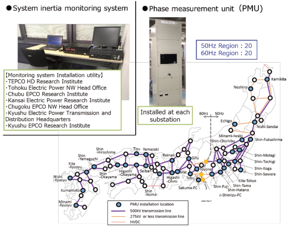
Fig.1 System configuration for inertia estimation
1.2 Development of a method for estimating system inertia
As described in Section 1,the inertia estimation method studied at the Kyushu Institute of Technology,which was applied in this project,focuses on the inter-area oscillation observed in the power system [8-10].In particular,the actual power system was simulated by a two-machine system model,as shown in Fig.2.The inertia was estimated by extracting the wide-area oscillation components through a fast Fourier transform (FFT) of the phase difference and power flow information between two points where PMUs are installed,as shown in Fig.3,and calculating the synchronizing power K by plotting the wide-area oscillation components of the phase difference and power flow (subsequently referred to as “the FFT method”).This method was selected for the continuous monitoring system developed in this project because it estimates inertia in real time from constantly measured data.In the FFT method,the aspect of wide-area oscillation is described by the oscillation equation using a two-machine system model,as show n in Fig.2.Considering that the wide-area oscillation components are absorbed by the inertia of synchronous machines G1 and G2,with phase amplitudes of A1 and A2,respectively,oscillation angular frequency of ω0,and synchronizing power K,the respective inertia constants H1 and H2[s]can be obtained as shown in Fig.2.
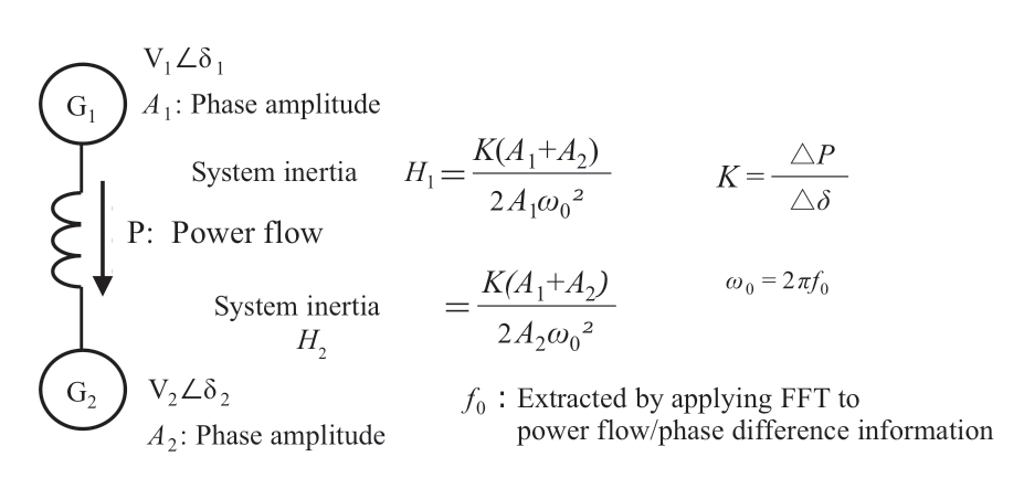
Fig.2 Two-machine system model and swing equation

Fig.3 Extraction and plotting of wide-area oscillation components of the phase difference and power flow data and calculation of the synchronizing power K
1.3 Results of system inertia estimation
Fig.4 shows an example of the inertia estimation results.Since it is practically impossible to observe the true value of inertia,we compared the results with the stacked value of inertia.The estimated result obtained using the developed method and the stacked value of inertia are indicated by the blue and red lines,respectively.Here,the stacked value of inertia is the total value of the generator inertia energy that can be observed by each electric utility,a portion of which includes the estimated values.The estimation results and comparison values exhibited a consistent trend of variation,and the effectiveness of the developed method was confirmed.However,the inertia estimation results remain slightly larger in magnitude compared to the stacked value of inertia.
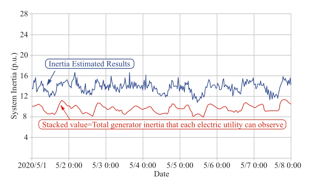
Fig.4 Example of real-time inertia estimation result
Fig.5 explains the factors that cause the inertia estimation results to change significantly,as well as future plans for the study.Factors that are not incorporated in the stacked value include the inertia contribution from the demand side,influence of the measurement point,and dynamic generator response,such as the frequency response.Regarding the demand-side inertia,the contribution of the inertia of private generators and induction motors were considered,and the calculations were reviewed by referring to calculations performed abroad.To determine the influence of the measurement point,it is ideal to conduct measurements at the center of inertia in each area of the two-machine system model to accurately estimate inertia,considering the difference due to the gap between that point and the point where the PMU is installed.With regard to the generator dynamic response,it is considered that the damping effect of the Δω-type power system stabilizers(PSSs) installed in some synchronous generators,which effectively suppress long-period oscillation components,has the potential to suppress the phase amplitude and increase the apparent inertia.At present,we are investigating and analyzing the abovementioned effects,and we expect to develop a fundamental method for observing system inertia by the end of this fiscal year.
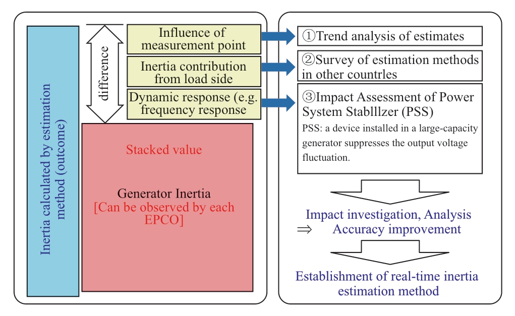
Fig.5 Towards the establishment of a real-time inertia estimation method
2 Development of inverter countermeasures for reduced inertia
Countermeasures to suppress the frequency drops caused by reduced inertia can be divided into three major categories: countermeasures using rotating machines,countermeasures using inverters,and load shedding.Countermeasures using rotating machines include nuclear,thermal,and pumped-storage generators and synchronous condensers.In this context,the project focused on countermeasures using inverters.This is because,with the expectation that a large amount of renewable energy will be introduced in the future,if it becomes possible to adopt countermeasures using inverters that will certainly be installed in renewable energy facilities,renewable energy will become a main power source,and the cost of countermeasures will be reduced.
It is to be noted that this does not mean that all existing countermeasures using rotating machines will be replaced by inverter countermeasures.Instead,the inclusion of inverter countermeasures has been in the lineup of new countermeasures to reduce the cost of other countermeasures(reducing the cost of introducing renewable energy).
2.1 Direction of development of inverter countermeasures for reduced inertia
Fig.6 shows the direction of the development of inverter countermeasures for reduced inertia.Various methods have been proposed worldwide as algorithms for inverter countermeasures for reduced inertia [11-23],They can be roughly divided into two categories: grid-following inverters (GFL),which are current-controlled inverters,and grid-forming inverters (GFM),which are voltage-controlled inverters.As GFL is expected to be realized by adding functions to conventional inverters,it is characterized by easy migration from conventional inverters.In contrast,although the new control method GFM is expected to have significant countermeasure effects,it also requires a fundamental review of rules,such as power system interconnection regulations (the Grid Code).
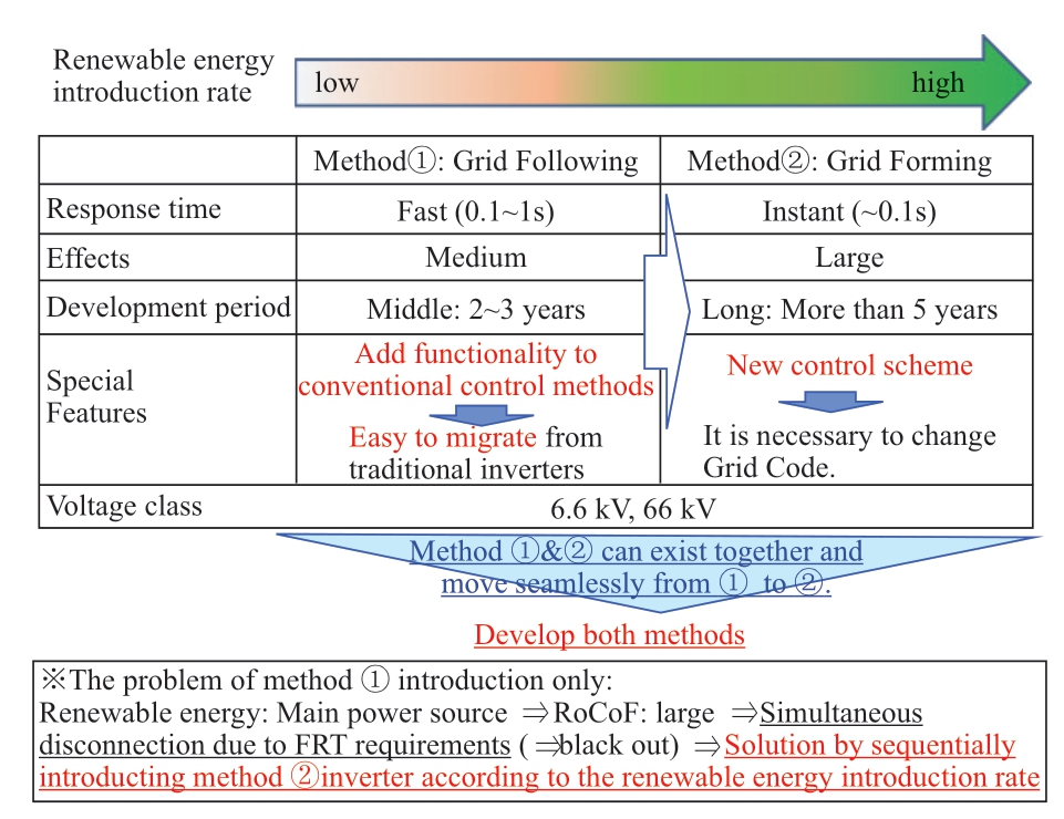
Fig.6 Types of inverters with inertia function and development plan
In addition,if only GFL countermeasures are adopted,its effect on RoCoF will be insignificant,and the RoCoF will gradually worsen with the introduction of renewable energy.If the RoCoF during a disturbance reaches an amount of introduction that deviates from the FRT requirements,there is a risk of the simultaneous disconnection of renewable energy.However,if the GFM is introduced to some inverters at this time,these problems can be solved,and the renewable energy introduction rate can be further increased.
Therefore,we believe that the introduction of renewable energy can be smoothly promoted by establishing GFM as a countermeasure device before the proportion of renewable energy reaches a certain level while using GFL countermeasures to avoid immediate problems.In this project,we are involved in developing both methods.
2.2 Concept of solar and storage battery inverter countermeasures for reduced inertia
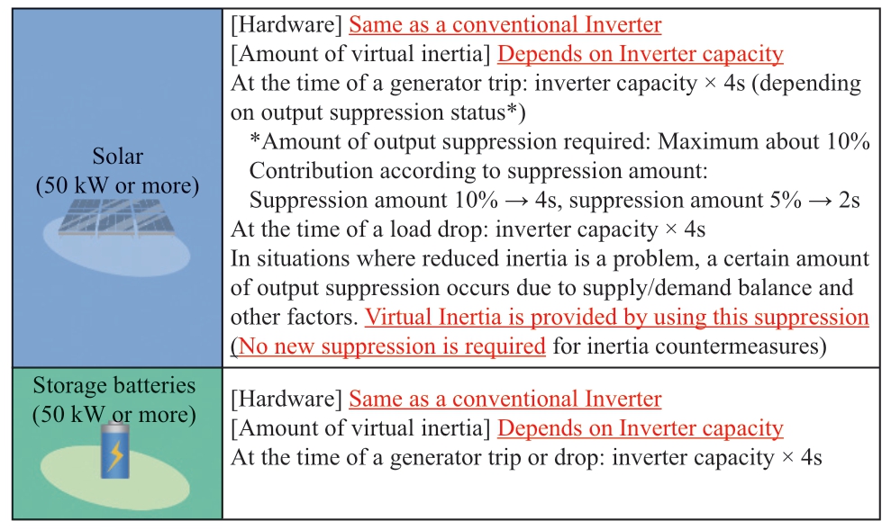
Table 1 presents the concept of equipping solar and storage batteries with inverter countermeasures to reduce inertia.The hardware of the inverter is the same as that of a conventional inverter for both the solar and storage batteries.Hardware changes due to countermeasures are unnecessary.The virtual inertia provided is determined by the capacity and performance of the inverter assuming that there is a sufficient energy source behind it.According to previous studies,the amount of virtual inertia is approximately inverter capacity × 4s.In addition,while virtual inertia designed for both solar and storage batteries is provided when there is a fall in the load,when there is a generator trip,suppression of the order of 10% of the inverter capacity is required in the case of solar power.However,when inertia becomes a problem,it is assumed that approximately 10% of the inverter capacity is suppressed owing to other constraints such as the supply/demand balance,which eliminates the need for additional suppression for virtual inertia.The virtual inertia will be provided by effectively utilizing energy that has been suppressed for other reasons.
Table 1 Inertia function requirements for solar and storage battery inverters
2.3 Example of the evaluation testing of inverter countermeasures for reduced inertia
Figure 7 shows an example of the test results for the inverter countermeasures for reduced inertia.The figure shows the change in the system frequency for a conventional inverter (constant P),GFL method inverter,and GFM method inverter when a generator trip occurs at renewable energy introduction (inverter-based resource (IBR))rates of 20%,40%,60%,and 80%.For the conventional inverter,the decrease in the system frequency increases with the renewable energy introduction rate.However,with the inverter countermeasures for reduced inertia,the system frequency drops were suppressed for each of the renewable energy introduction rates from 20% to 60% for both methods,which confirmed the effectiveness of the countermeasures.In addition,focusing on the case where the renewable energy introduction rate is 80%,control with GFL is unstable,whereas operation with GFM is stable,which shows that GFM is necessary at an extremely high renewable energy introduction rate.
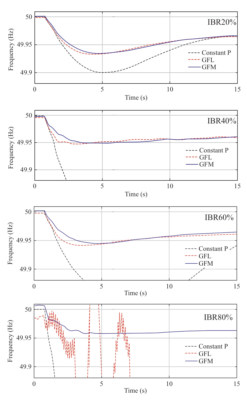
Fig.7 Test results for the inverter countermeasures for reduced inertia
To complete the project by the end of February 2022,we will compile standard equipment specifications and evaluation test methods for inverter countermeasures for reduced inertia based on the knowledge gained through equipment development and evaluation tests.
3 Conclusion
This study describes the efforts to address the problem of reduced inertia,which is a problem associated with the large-scale integration of renewable energy.
In Section 1,we described the development of a system inertia estimation technique that focuses on the inter-area oscillation component and facilitates the monitoring of the system inertia.The inertia estimated by this method includes the inertia of the generators of the electric utility and that of the demand,which enables a more accurate observation of the system inertia than the conventional method based on the stacked value of generators.
In Section 2,we described the development of inverter countermeasures for reduced inertia as a countermeasure device for the problem of reduced system inertia.Both the GFM and GFL methods are being developed for the same inverters.While GFL will be used for frequency nadir mitigation from the viewpoint of response speed,GFM can similarly function as a generator,despite capacity constraints,and will provide virtual inertia to improve both the frequency nadir and RoCoF.
We present an example of the application of this technology.From a mid-to-long-term perspective,we predict the periods when the system inertia reduces because of the trend record of the system inertia estimation result and consider it in the operation plan.However,from a short-term perspective,the system inertia of the next day,including the virtual inertia provided by the GFM,is predicted from the system inertia estimated up to the previous day.When this is projected to fall below the minimum requirement,adjustments to other countermeasures,such as generator paralleling,are introduced.On the day itself,the minimum required inertia is secured by adding the countermeasures adjusted the previous day to the predicted system inertia.
By utilizing the system inertia observation method and ensuring that inverters are equipped with countermeasures for reduced inertia,it will be possible to expand the amount of renewable energy introduced in the future.
Acknowledgements
This study is based on the results obtained from a project (JPNP19002) commissioned by the New Energy and Industrial Technology Development Organization (NEDO).This work was supported by the TEPCO Power Grid,Inc.,Tohoku Electric Power Network Co.,Inc.,Chubu Electric Power Co.,Inc.,Chubu Electric Power Grid Co.,Inc.,Kansai Transmission and Distribution,Inc.,Chugoku Electric Power Transmission and Distribution Co.,Inc.,Kyushu Electric Power Co.,Inc.,Kyushu Electric Power Transmission and Distribution Co.,Inc.,Takaoka Toko Co.,Ltd.,Tokushima University,and Osaka Prefectural University.
Declaration of Competing Interest
We declare that we have no conflict of interest.
References
[1]METI (2021) Japan’s Roadmap to “Beyond-Zero” Carbon.https://www.meti.go.jp/english/policy/energy_environment/global_warming/roadmap/index.html.Accessed 15 Sep.2021
[2]METI (2021) Present Status and Promotion Measures for the introduction of Renewable Energy in Japan.https://www.meti.go.jp/english/policy/energy_environment/renewable/index.html.Accessed 14 Mar.2022
[3]P M Ashton,C S Saunders,G A Taylor,et al.(2015) Inertia Estimation of the GB Power System Using Synchrophasor Measurements.IEEE Transactions on Power Systems,30(2):701-709
[4]P Wall,V Terzija (2014) Simultaneous Estimation of the Time of Disturbance and Inertia in Power Systems.IEEE Transactions on Power Delivery,29(4): 2018-2031
[5]T Inoue,H Taniguchi,Y Ikeguchi,et al.(1997) Estimation of Power System Inertia Constant and Capacity of Spinning-reserve Support Generators Using Measured Frequency Transients.IEEE Transactions on Power Systems,12(1): 136 -143
[6]ENTSO-E (2018) Future system inertia.https://www.entsoe.eu/Documents/Publications/SOC/Nordic/Nordic_report_Future_System_Inertia.pdf.Accessed 15 Sep.2021
[7]ESIP (2018) Implementation of Inertia Monitoring in ERCOT –What’s It All About?.https://www.esig.energy/implementationof-inertia-monitoring-in-ercot-whats-it-all-about/.Accessed 15 Sep.2021
[8]N Hosaka,K Yoshiyama,T Ohara,et al.(2022) Development of Basic Technology for Estimating System Inertia in Real Time.The paper of CIGRE 2022 Kyoto Symposium,Kyoto,3-8 Apr.2022
[9]K Ueda,T Tsunawaki,M Watanabe,et al.(2018) Evaluation of Synchronizing Power and Inertia of Wide-area Oscillation Mode based on Phasor and Power Flow Information.The paper of Technical Meeting on Power Systems Engineering,IEE Japan,55-60,26 Sep.2018
[10]Y Matsukawa,J Terashi,M Watanabe,et al.(2017) Power systems inertia evaluation associated with PV installation by frequency analysis of inter-area oscillation based on phasor measurements.Journal of International Council on Electrical Engineering,7:1,153-158
[11]A Tayyebi,D Groß,A Anta,et al.(2019) Interactions of Grid-Forming Power Converters and Synchronous Machines – A Comparative Study.https://arxiv.org/pdf/1902.10750.pdf.Accessed 15 Sep.2021
[12]O Schömann,T Bülo,C Hardt,et al.(2019) Experiences with Large Grid-Forming Inverters on Various Island and Microgrid Projects.The paper of 4th International Hybrid Power Systems Workshop,Crete,22-23 May 2019
[13]S Maeyama,K Shirasaki,H Amano (2019) Instability of Inertial Response Control for Compensation of Reduced Inertia.The paper of the Power and Energy Society annual conference 2019,Paper 110,Hiroshima,3-6 Sep.2019
[14]A Tayyebi,F Dörfler,F Kupzog,et al.(2018) Grid-Forming Converters – Inevitability,Control Strategies and Challenges in Future Grids Application.The paper of CIRED Workshop,Paper 0236,Ljubljana,7-8 Jun.2018
[15]T Kanda,Y Noro (2018) Overcurrent suppression of inverters that can continue operation in case of system fault in isolated system(part2).The paper of Technical Meeting on Power Systems Engineering,IEE Japan,91-96,26 Sep.2018
[16]U Tamrakar,D Shrestha,M Maharjan,et al.(2017) Virtual Inertia: Current Trends and Future Directions.Applied Sciences 7(7):654.DOI:10.3390/app7070654
[17]J Hu,SWang,W Tang,et al.(2017) Full-Capacity Wind Turbine with Inertial Support by Adjusting Phase-Locked Loop Response.IET Renewable Power Generation,11(1): 44-53
[18]V Natarajan,G Weiss (2017) Synchronverters With Better Stability Due to Virtual Inductors,Virtual Capacitors,and Anti-Windup.IEEE Transactions on Industrial Electronics,64(7):5994-6004
[19]S Sekizaki,N Yorino,Y Sasaki,et al.(2017) A Development of Single-Phase Pseudo-Synchronizing Power Inverter Considering Dynamic Characteristic of Synchronous Machine.The paper of technical meeting on semiconductor power converter,IEE Japan,61-66,9 Mar.2017
[20]M Tuyuki,Y Ota,T Nakajima (2017) Virtual Synchronous Generator Control and Grid Voltage Control by Reactive Power of Grid-connected Inverter for Power System Stabilization.The paper of the Power and Energy Society annual conference 2017,Paper 35,Tokyo,5-7 Sep.2017
[21]L Shang,J Hu,X Yuan,et al.(2016) Understanding Inertial Response of Variable-Speed Wind Turbines by Defined Internal Potential Vector.Energies 10(1):22.DOI 10.3390/en10010022
[22]X Wang,J M Guerrero,F Blaabjerg,et al.(2012) A Review of Power Electronics Based Microgrids.International Journal of Power Electronics,12(1): 181-192
[23]Y Hirase,K Abe,K Sugimoto,et al.(2012) A Grid Connected Inverter with Virtual Synchronous Generator Model of Algebraic Type.IEEJ Transactions on Power and Energy 132(4): 371-380
[24]National Grid ESO (2021) GC0137 Draft final Modification Report.https://www.nationalgrideso.com/document/220511/dow nload.Accessed 14 Mar.2022
[25]Maui Electric (2020) Draft Model Power Purchase Agreement For Renewable Dispatchable Generation (PV + BESS) With CBRE Component.https://www.hawaiianelectric.com/documen ts/clean_energy_hawaii/selling_power_to_the_utility/competitive_bidding/20200728_cbre_lanai_combined_rdg_ppa_redline.pdf.Accessed 14 Mar.2022
[26]AEMC (2020) National Electricity Rules Version 153.https://www.aemc.gov.au/sites/default/files/2020-11/NER%20v153%20full_0.pdf.Accessed 14 Mar.2022
[27]AEMO (2021) White Paper: Application of Advanced Gridscale Inverters in the NEM.https://aemo.com.au/-/media/files/initiatives/engineering-framework/2021/application-of-advance d-grid-scale-inverters-in-the-nem.pdf.Accessed 14 Mar.2022
[28]NREL (2020) Power HIL evaluation of inverter controls for 100%inverter-based bulk power systems A power electronics grid integration case study.https://www.nrel.gov/aries/assets/pdfs/pegi-hoke.pdf.Accessed 14 Mar.2022
[29]Aurecon (2018) Hornsdale Power Reserve.https://www.aurecon group.com/-/media/files/downloads-library/thought-leadership/aurecon-hornsdale-power-reserve-impact-study-2018.pdf.Acces sed 14 Mar.2022
[30]ElectraNet (2017) Dalrymple ESCRI-SA Battery Energy Storage Project SEPA Energy Storage Working Group.https://www.escri-sa.com.au/globalassets/reports/escri-sa-presentation-tosepa-energy-storage-wg---april-2020.pdf.Accessed 14 Mar.2022



Received: 11 November 2021/Accepted: 19 April 2022/Published: 25 June 2022
Hiromu Hamada hamada.hiromu@tepco.co.jp
Yoshitaka Kusayanagi kusayanagi.yoshitaka@tepco.co.jp
Masamoto Tatematsu tatematsu.masamoto@a2.kepco.co.jp
Masayuki Watanabe watanabe@ele.kyutech.ac.jp
Hiroshi Kikusato hiroshi-kikusato@aist.go.jp
2096-5117/© 2022 Global Energy Interconnection Development and Cooperation Organization.Production and hosting by Elsevier B.V.on behalf of KeAi Communications Co.,Ltd.This is an open access article under the CC BY-NC-ND license (http://creativecommons.org/licenses/by-nc-nd/4.0/).
Biographies
Hiromu Hamada has been working for TEPCO since 2005.He received the degree of Doctor of Engineering from Waseda University,Tokyo,Japan,in 2011.He is currently a researcher at the TEPCO Research Institute.His fields of interest include distribution system operation and countermeasure technology owing to the massive introduction of renewable energies.
Yoshitaka Kusayanagi has worked for TEPCO since 2000.He is currently a researcher at the TEPCO Research Institute.His fields of interest include power system operation and estimation of system inertia technology.
Masamoto Tatematsu was born in Japan in 1970.He received his Master’s degree of electrical engineering from the University of Tokyo in 1995.He has worked at the Kansai Electric Power Company,Inc.(KEPCO) since 1995.He has also been a guest professor at Osaka Electro-Communication University(OECU) since 2020.His research interests include power system stability control.
Masayuki Watanabe received the B.S.,M.S.,and D.Eng.degrees in Electrical Engineering from Osaka University,Osaka,Japan,in 2001,2002,and 2004,respectively.Currently,he is a Professor at the Department of Electrical and Electronic Engineering,Kyushu Institute of Technology,Japan.His research interests lie in the areas of analysis and control of power systems.
Hiroshi Kikusato received the Ph.D.degree in electrical engineering from Waseda University,Tokyo,Japan,in 2018.He is currently a research scientist with the Fukushima Renewable Energy Institute,AIST (FREA).His research interests include power system control and management,demand-side energy management using electric vehicles,and hardware-in-the-loop testing of distributed energy resources and microgrids.
(Editor Yanbo Wang)
