0 Introduction
Renewable energy sources are being used in conjunction with AC networks to reduce CO2 emission.These renewable energy systems utilize inverters to connect to an AC power system.In typical power system operation,the renewable energy source supplies power to AC systems to maintain high efficiency operation.However,large disasters have recently occurred in many parts of the world and caused lengthy blackouts.The operation of an electric power supply is required during these blackouts to save lives.If a microgrid is appropriately designed,power supply to a microgrid can be maintained during extended blackouts.The key technology requirement to achieve this is the design of control inverters using renewable energy.
In this study,we considered a standalone microgrid supplied by inverter power sources without a rotating generator.
Uninterruptible power systems (UPSs) can supply power to a load with constant voltage and frequency.However,it is impossible to operate multiple UPSs in an AC synchronous network.
Three-phase voltage signals determining the inverter output voltages were obtained from frequency order using an integral function in a basic control scheme reported in [1].However,when the detected voltage phase signal was fed back to the three-phase voltage signals,and it was not easy to get stable operation.
Other studies proposed a new control approach and demonstrated its effectiveness in an actual standalone distribution network in which power was supplied only by inverter power sources [2,3].This will be discussed in a later section.Some studies have developed control schemes for constant frequency operation; however,flexible power distribution among inverters was not considered owing to restricted frequency [4,5].The method proposed in [6]fails to achieve frequency control because measured load power was used for re-dispatching calculation,increasing the complexity of the calculation.Several studies have demonstrated the limited applicability of resistive-only loads to actual networks [7-9].A control equation was developed in [10]for a two-inverter system; however,it has limited applicability to other system configurations.A virtual synchronous power system that included the swing equation of generators was proposed in [11,12].Several other virtual synchronous inverters have been proposed [13];however,they fail to provide stable operation in standalone microgrids.This study considers a combination of a master grid forming inverter and grid following inverters that function as slave inverters with an energy management system in a standalone microgrid.This paper summarizes our previous research [14-16].
1 Parallel inverter operation in a standalone distribution network
The inverter circuit containing a full bridge IGBT inverter,DC battery,connecting transformer,and control circuit is shown in Fig.1,where Vsys is the distribution bus voltage,and Vinv is the voltage generated by the inverter.The symbol θ is the angle of voltage.
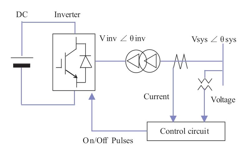
Fig.1 Inverter circuit
Figure 2 shows a microgrid comprising three inverters as a power source for standalone operation without a rotating generator.
Actual parallel operation using the configuration shown in Fig.2 was performed,and the results were reported in [2,3].In this network,four 200 kW fuel-cell inverters were connected to a 6.6 kV bus to supply power to the load.The same control was applied to these inverters.Stable parallel operation was achieved via specialized control of the voltage phase detection block and the specialized voltage amplitude control block.Typically,a voltage detection circuit includes a PI control function in its control block; however,the applied control has a proportional function without an integral function.Therefore,an offset remains,and consequently,the offset of frequency control remains.In the voltage amplitude control,a proportional function is also applied; therefore,the offset remains in the voltage control output.Both offsets enable parallel operation of four inverters that simulate droop control to balance power operation by small errors without mutual control signals between inverters.Although this is a smart control strategy,it does not guarantee a balanced power distribution among the four inverters.Moreover,it has been reported that power balance errors occur.These inverters had identical design and were made by the same manufacturer;therefore,the errors were small.However,more reliable power distribution among inverters is required.This study proposes a reliable and controllable power distribution control scheme for an inverter in a microgrid.
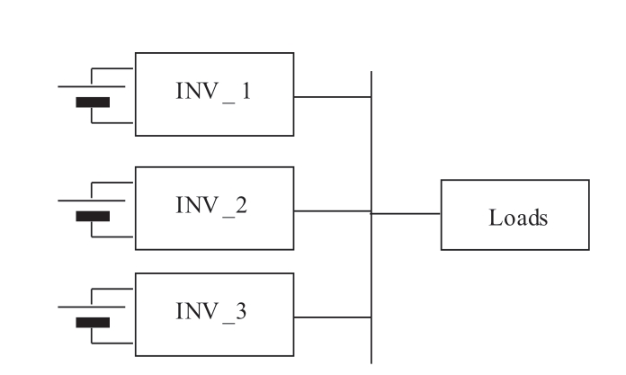
Fig.2 Microgrid inverter-supplied power diagram
2 Proposed inverter control
2.1 Control design
As shown in Fig.2,the microgrid comprises three inverters: INV_1,INV_2,and INV_3.INV_1 is the master inverter,and INV_2 and INV_3 are slave inverters.INV_1 maintains the frequency and voltage amplitude.Furthermore,a droop characteristic was added to reduce the frequency when the active power of INV_1 increases.In addition,a droop characteristic was added to reduce the AC voltage when the reactive power increases.
Figure 3 shows the control block of the master inverter.Signals in the double square box were fed from an energy management system (EMS).Fref is a frequency reference,50 Hz,and Pref1 is an active power reference obtained from the EMS.Details of the EMS are provided later in this section.The difference between Pref1 and Pmeasured is added to Fref through the droop gain D11.The angle of the voltage signal is calculated by an integral function of 2 π/s from the frequency signal.The difference between Qref1 and Qmeasured is added to Vref through the droop gain D12 and is compared with the measured voltage and then fed to an automatic voltage control (AVR) function.The angle θ and the output E of the AVR are used to calculate the threephase voltage signals for the inverter as

PWM logic with a triangle carrier wave was applied to generate on/off pulses for the inverter switching elements.This inverter is one of grid forming inverters.
Figure 4 shows the control block for the slave inverters INV_2 and INV_3.These inverters employ conventional active power control (APR) and a reactive power control(AQR).In the slave inverters,the frequency is measured,and the error signal is added to the APR loop through the droop gain of D21.The system voltage is measured and the error signal is added to the AQR loop through the droop gain of D22.The outputs of APR and AQR are fed to the current control [13].Two-axis (dq) non-interacting control is applied in normal way.This slave inverter is one of grid following inverters.INV_3 has the same control as INV_2.
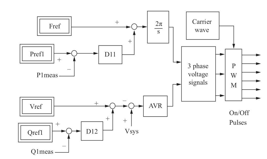
Fig.3 Control block of INV_1
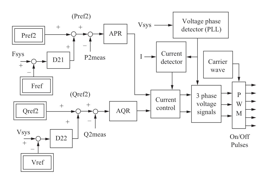
Fig.4 Control block of INV_2 and INV_3
This novel design combines a grid forming inverter(INV_1) and grid following inverters (INV_2 or INV_3).
2.2 Simulation study
A simulation study was performed to evaluate the performance of the proposed control using the ATP program[17].Table 1 shows the ratings of the inverters used in the simulation.
Table 1 Inverter ratings

(1) Load change (Case 1)
Two inverters,INV_1 and INV_2,were used in the operation.An initial load of 1 MW was applied.Loads of 0.2 MW were added at 2 s and 3 s.The load power factor was 0.95.Figure 5 shows the simulation results.Figs.5(a),(b),(c),and (d) show the active power,reactive power,frequency deviation,and voltage,respectively.Before 2 s,the 1 MW load was shared by INV_1 and INV_2 equally.The reference values Pref and Qref for INV_1 and INV_2 were set to zero; the frequency deviations remained at –1 Hz according to the droop characteristics.After 2 s,additional load was supplied by INV_1,but the total load was shared equally after 2.5 s.A 0.2 MW load was added at 3 s.The same load sharing behavior was observed after 2 s.The frequency deviation reached –1.5 Hz.The reactive power was also shared between INV_1 and INV_2.The measured active power was not equal to the Pref value because of the droop effect.Moreover,the voltage dropped according tothe droop characteristics.Consequently,the frequency and voltage remained at the operating points determined by the droop characteristics,and stable operation was achieved.Fig.5 (e) shows the three-phase voltages at 4 s.
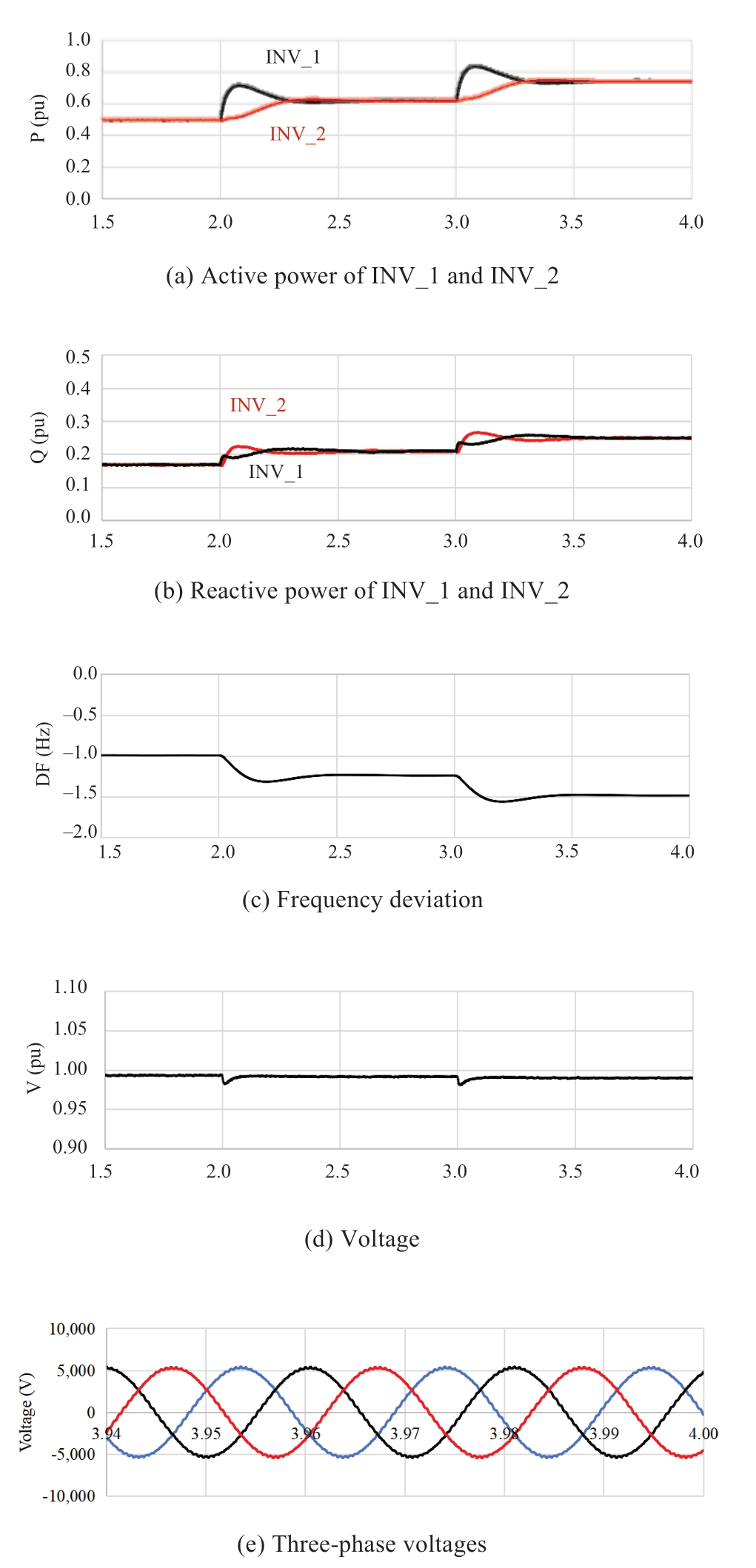
Fig.5 Load increase (Case 1)
(2) Change of P reference (Case 2)
An initial load of 1 MW and two inverters,INV_1 and INV_2,are considered,as in Case 1.At 2 s,Pref2 of INV_2 is changed from 0 p.u.to 0.5 p.u.,and at 3 s,Pref1 of INV_1 is changed from 0 p.u.to 0.5 p.u.Fig.6 shows the simulation results.The active power of INV_2 increases without delay owing to the fast inverter control,as shown in Fig.6 (a).By contrast,the active power of INV_1 decreases because the load remains at 1 MW; however,the frequency increases along with the frequency droop characteristics of INV_1.At 3 s,Pref1 is increased step wise,and the active power of INV_1 increases gradually owing to the integral function used to obtain the voltage angle.At 3.5 s,INV_1 and INV_2,share the load and stable operation is achieved.The frequency deviation reaches zero because the sum of Pref1 and Pre2 becomes equal to the load (1 MW).
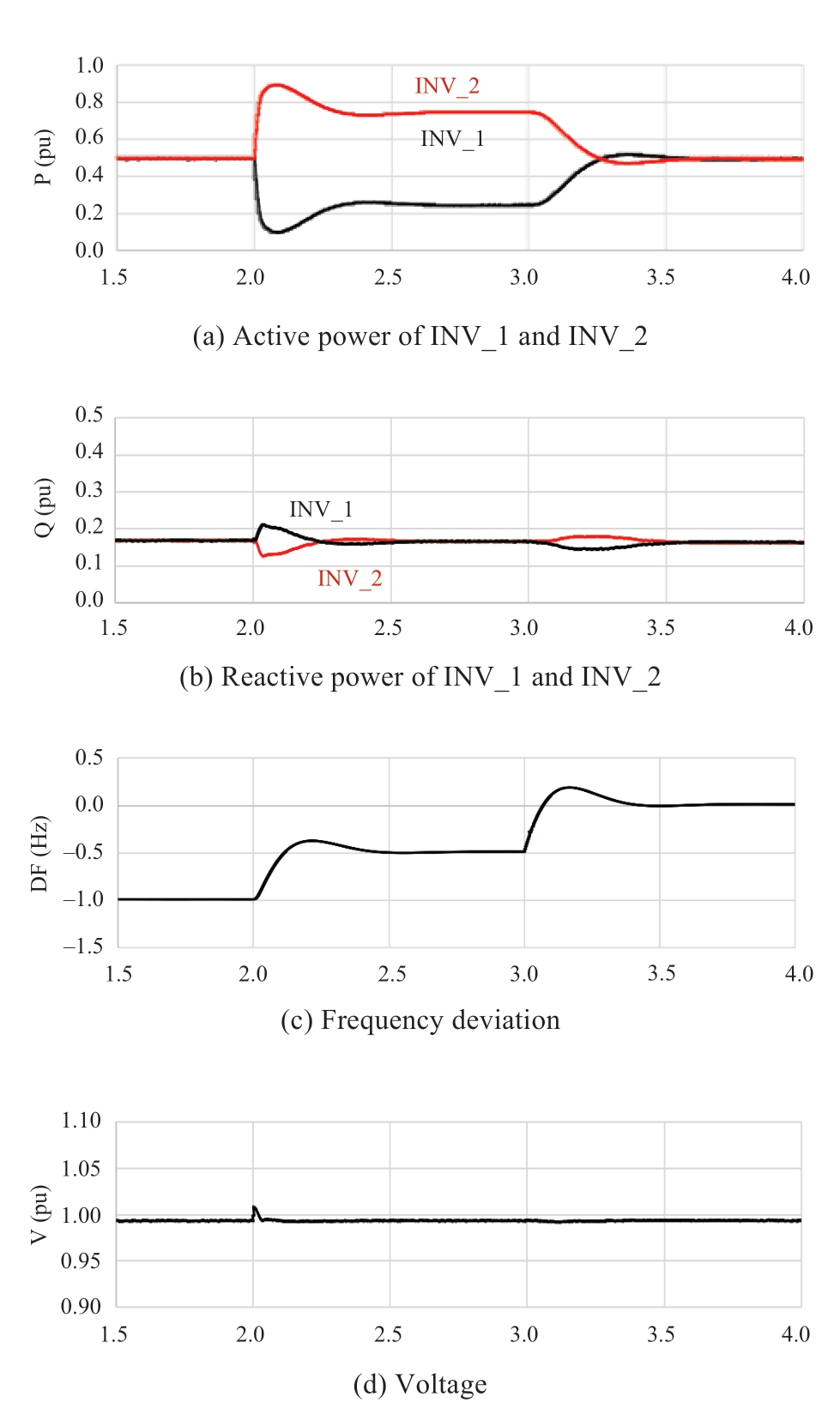
Fig.6 Change of P order (Case 2)
(3) Change of Q reference (Case 3)
The results of Case 3 are shown in Fig.7.The initial condition was the same as that for Case 1.At 2 s,Qref2 of INV_2 is increased from 0 p.u.to 0.25 p.u.,and at 3 s,the Qref1 of INV_1 is increased from 0 p.u.to 0.25 p.u.The reactive power of INV_2 increases rapidly at 2 s,and the reactive power increases gradually at 3 s,owing to the delay of AQR.Finally,the reactive power is shared equally by the two inverters.In this case,the voltage rises because of reactive power injection.
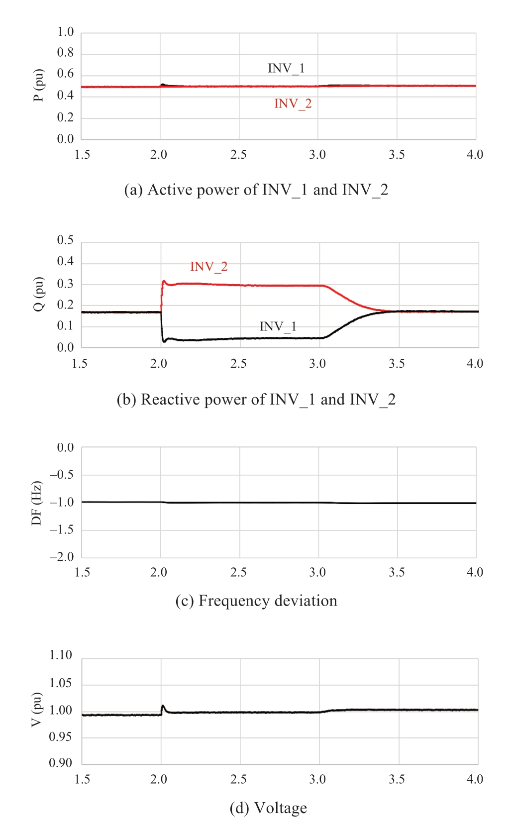
Fig.7 Change of Q order (Case 3)
(4) Three-inverter operation (Case 4)
Case 4 was used to evaluate system performance in multiple-inverter operation mode.In this case,INV_3 with a rating of 2 MW is added,and the initial load is assumed to be 2 MW.Initially,INV_1 and INV_2 supply 0.5 MW each of the load,and INV_3 supplies 1 MW; specifically,they have the same output as that for 0.5 p.u.based on the self-capacity base.At 3 s,a 0.25 MW load is added,and at 4 s,another 0.25 MW is added.The simulation results are shown in Fig.7.Evidently,in a configuration with more than two inverters,the load is shared and stable operation is achieved.The plotted curves of INV_2 and INV_3 shown in Figs.8 (a) and (b),respectively,overlap.
In these case studies,the load increase is considered to be a severe condition.
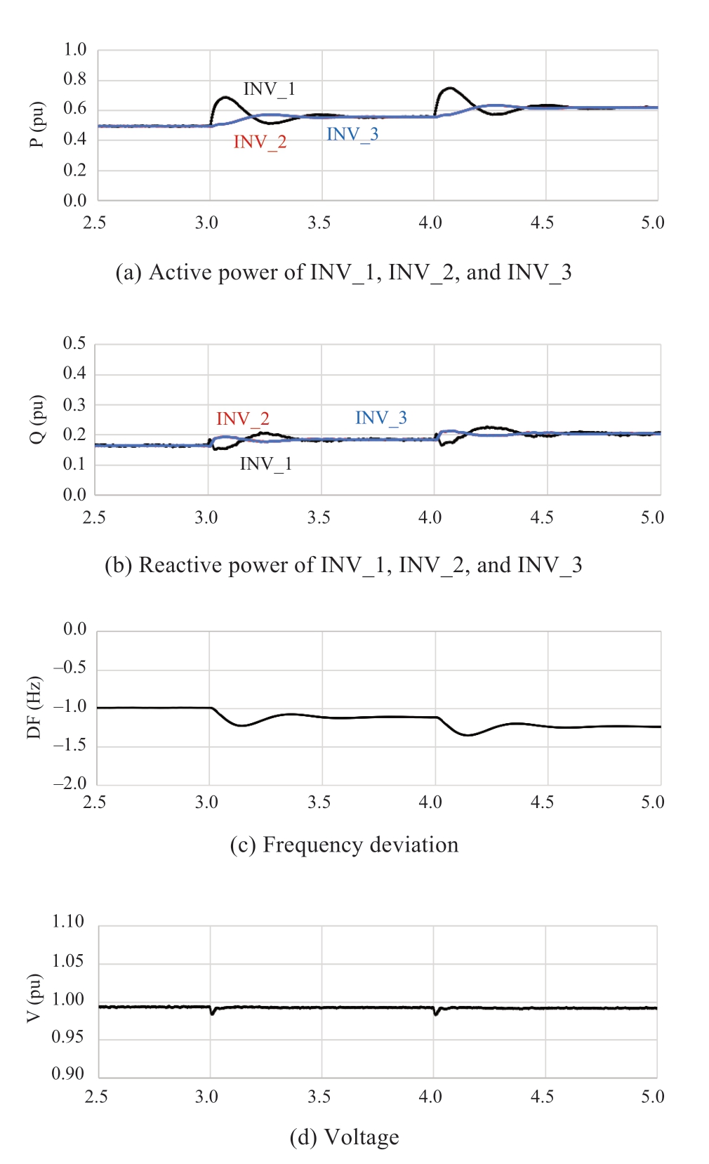
Fig.8 Load increase with three inverters (Case 4)
These results indicate that the proposed inverter control is effective for obtaining stable operation in a microgrid in which power is supplied only by inverter power sources.The proposed control uses the frequency signal for active power distribution and the voltage amplitude for reactive power distribution.However,the proposed control has a disadvantage; when a large load is connected,the master inverter (INV_1) supplies the initial large load and if its output exceeds the ratings,it shuts down.This problem can be addressed by applying a suitable EMS,as explained in the next section.
2.3 Coordinated control of EMS
The EMS applied the inverter power source microgrid to coordinate with the inverters.Figure 9 shows the inputs and outputs of EMS.In Fig.9 (a),only signals relating to coordinated control are shown.
In a conventional AC power system,frequency control is applied to maintain the frequency and dispatch loads.Such a control is not suitable for the proposed inverter system because the inverter has quick response,and the frequency is determined by the master inverter.Fig.9 (b)shows the coordinated control,in which the active power output of master inverter (INV_1) is measured,and the power difference is used to modify the reference value,Pref2.The modification is performed by adding a correction using adequate functions to the basic reference value that is determined using another load dispatch calculation not described here.
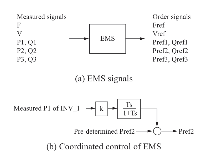
Fig.9 EMS coordinated control
Figure 10 shows simulation results of the coordinated control.The simulation condition was the same as that of Case 1.Comparing Fig.10 with Fig.5(a),it is observed that the output of INV_2 increases and shares the load with INV_1 to achieve a better response.The k in Fig.9 (b) is a coefficient to convert P1 to a p.u.value based on the selfcapacity,and the time constant T is 0.2 s.
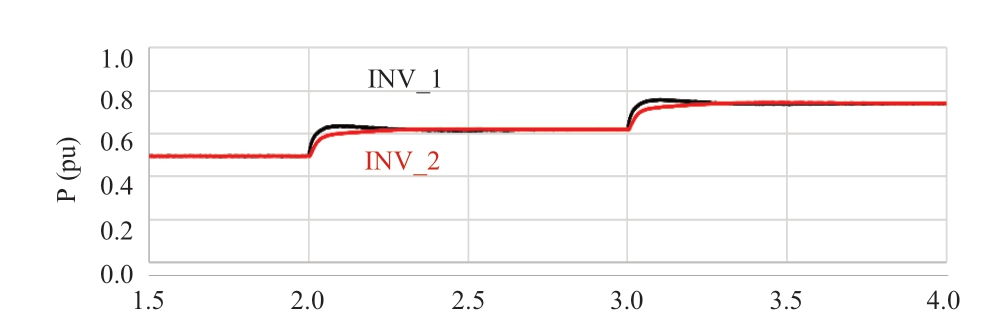
Fig.10 Active power with coordinated control
3 Conclusion
A new control approach for grid forming and grid following inverters was proposed for microgrids that operate in a standalone condition without synchronous generators.The proposed approach provides coordinated control of the power supply for the stable operation of microgrids without the control errors reported in previous studies [2,3].This new control scheme combines the use of a grid forming inverter and grid following inverters to prevent the shutdown of a grid forming inverter when its output exceeds its power limit.
In a future study,the proposed approach will be applied to an actual microgrid to verify the effectiveness and utility of the coordinated control.
Declaration of Competing Interest
We declare that we have no conflict of interest.
References
[1]Chandorkar M C,Divan D M,Adapa R (1993) Control of parallel connected inverters in standalone ac supply systems,IEEE Transactions on Industry Applications,29(1): 136-143
[2]Sumita J,Nishioka K,Noro Y (2007) A study of isolated operation of a microgrid configured with new energy generators,IEEJ Transactions on Power and Energy,127(1): 145-153 (in Japanese)
[3]Arai J,Fujino S,Tanaka H,et al.(2008) Coordinated control for isolated distribution networks supplied by inverter power sources,Proceedings of 2008 IEEE Power and Energy Society General Meeting,24 July
[4]Sumita J,Nishioka K,Noro Y,et al.(2009) A verification test result of isolated operation of a microgrid configured with new energy generators and a study of improvement of voltage control,IEEJ Transactions on Power and Energy,129(1): 57-65 (in Japanese)
[5]Tanaka R,Arai J (2009) Simulation of an inverter on ATPdraw,IEEJ-EIT Joint Symposium on Advanced Technology in Power Systems,Bangkok,Thailand,PSE-09-198,26-27 November
[6]Mohd A,Ortjohann E,Sinsukthavorn W,et al.(2009)Isochronous load sharing and control for inverter-based distributed generation,Proceedings of 2009 International Conference on Clean Electrical Power,9-11 June,324-329
[7]Zhang X,Zhong Q-C,Zhang H,et al.(2010) Proportional load sharing method for parallel connected inverters,2010 IEEE International Symposium on Industrial Electronics,4-7 July,2261-2265
[8]Zhong Q-C (2013) Robust droop controller for accurate proportional load sharing among inverters operated in parallel,IEEE Transactions on Industrial Electronics,60(4): 1281-1290
[9]Subhajyoti M,Pourya S,Mehdi F (2015) Impedance shaping for improved load sharing among inverters in AC microgrid,Proceedings of 2015 IEEE Energy Conversion Congress and Exposition,20-24 September,738-744
[10]Konstantopoulos G C,Zhong Q-C,Ren B,et al.(2014) Bounded droop controller for accurate load sharing among paralleled inverters,Proceedings of the 2014 American Control Conference,934-939
[11]Sakimoto K,Miura Y,Ise T (2012) Stabilization of a power system including inverter type distributed generators by the virtual synchronous generator,IEEJ Transactions on Power and Energy,132 (4) 341-349
[12]Sakimoto K,Miura Y,Ise T (2013) Characteristics of parallel operation of inverter type distributed generators operated by a virtual synchronous generator,IEEJ Transactions on Power and Energy,133(24): 186-194 (in Japanese)
[13]D’Arco S,Suul J A (2013) Virtual synchronous machines–Classification of implementations and analysis of equivalence to droop controllers for microgrids,Proceedings of 2013 IEEE Grenoble Conference,16-20 June,DOI:10.1109/PTC.2013.6652456
[14]Arai J (2015) New inverter control in an isolated microgrid composed of inverter power sources without synchronous generator,Proceedings of IEEJ-EIT Joint Symposium on Advanced Technology in Power Systems,6 March
[15]Arai J,Yokoyama R (2015) Resilient and expandable distribution network for smart community in asian countries and islands,The 5th China International Energy and Energy Storage Technology and Equipment Expo,Beijing,15-17 June
[16]Naoi S,Arai J,Noro Y (2017) Control for inverter power sources in a standalone microgrid,IEEJ Transactions on Power and Energy,137(6): 426-433 (in Japanese)
[17]Arai J,Haginomori E,Koshiduka T,et al.(2016) Power system transient analysiis,Jhon Willy,ISBN: 978-1-118-73753-8


Received: 3 November 2021/Accepted: 5 May 2022/Published: 25 June 2022
Junichi Arai arai@cc.kogakin.ac.jp
Yasuhiro Taguchi taguchi@eetri.net
2096-5117/© 2022 Global Energy Interconnection Development and Cooperation Organization.Production and hosting by Elsevier B.V.on behalf of KeAi Communications Co.,Ltd.This is an open access article under the CC BY-NC-ND license (http://creativecommons.org/licenses/by-nc-nd/4.0/).
Biographies
Junichi Arai received BS and MS degrees in Electrical Engineering from Waseda University in 1970 and 1972,respectively.He received a doctorate degree in Engineering from Tokyo Metropolitan University in 1995 in Japan.He joined Toshiba Corporation in 1972 as a power systems research engineer.He became a professor in the Engineering Department of Kogakuin University,Tokyo,in 2006.He is now a professor emeritus at Kogakuin University and executive researcher at the Energy and Environment Technology Research Institute.His research focuses on power system control,power electronics applications,microgrid control,and power quality.He is a fellow of IET,C.Eng.,senior member of IEEE,and fellow of IEEJ.
Yasuhiro Taguchi received BS and MS degrees in Electrical Engineering from Waseda University in 1979 and 1981,respectively.He joined Toshiba Corporation in 1981,where he was engaged in research on power system analysis,including grid stabilization and evaluation of microgrids and smart grids.He began conducting research on microgrids at the Energy and Environment Technology Research Institute in 2020.His research focuses on power system stabilization,monitoring and control,and microgrid analysis and evaluation.
(Editor Yajun Zou)
