0 Introduction
Power system on-site work refers to any organized,planned, and purposeful power system production activities on-site, including power plant construction, maintenance,operation, and other power production activities throughout power generation, transmission, substation, and distribution.During power system on-site work, dressing and neglect of safety rules can cause fatal injuries to operators and devices;thus, it is necessary to identify and manage various risks to guarantee the safety of power system on-site work in a fast and accurate manner.Currently, various terminal equipment are often used to collect on-site work data and upload to the cloud platform for risk identification [1].However,with an increasing number of terminal equipment and sampling data, the long-distance transmission of massive data causes network congestion and delay; thus, prior online risk identification is difficult, but only applicable for postaccident analysis and tracing.Therefore, a “cloud-edge-end”collaborative system architecture [2], as shown in Fig.1,transplants the lightweight risk identification algorithm from the cloud platform to the edge computing equipment,which shortens the data transmission distance and achieves the local identification of on-site work risks in real-time.Moreover, the lightweight risk identification algorithm should meet the requirements of high accuracy and fast speed.
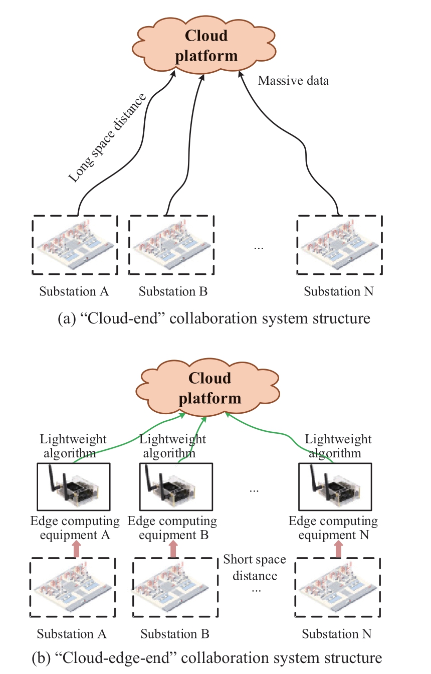
Fig.1 Comparison between “cloud-end” structure and“cloud-edge-end” structure
Risk identification in power system on-site work is generally achieved through object detection algorithms,which are divided into traditional object detection algorithms and deep learning-based object detection algorithms.Traditional object detection algorithms based on manual feature extraction, such as VJ detector [3],histogram detector [4], and DPM algorithm [5], suffer from high computational effort, low accuracy, and speed.Moreover, the manually designed features are not flexible to changes in environmental diversity.Thus, the traditional method is not suitable for risk identification of on-site work.Deep learning-based object detection algorithms include one-stage detection and two-stage detection.The two-stage object detection algorithm is represented by the Faster R-CNN [6] proposed by Shaoqing et al.(2015),which first generates region proposals through the region proposal network, and then generates bounding boxes and classification information from these region proposals.The detection accuracy of the two-stage algorithm is high;however, the detection speed is slow.Thus, it cannot meet the requirement of real-time risk identification for on-site work.A one-stage object detection algorithm is represented by YOLO [7-10] and SSD [11].These algorithms can directly generate the object bounding boxes and categories in a network; therefore, their detection speed is faster than the two-stage algorithms, with almost no degradation in accuracy, which can meet the requirements of real-time risk identification in complex on-site work scenarios.However,the one-stage algorithms have deep network layers, large amounts of parameters, and high requirements for hardware performance, which are not suitable for deployment at the edge.Therefore, a variety of lightweight algorithms have been proposed, such as YOLO-Tiny [12, 13] and YOLO Nano [14].Compared with the previous lightweight algorithms, YOLOv4-Tiny has a huge improvement in detection accuracy and speed and is often used in embedded platforms deployed at the edge.
Because the network structure of the YOLOv4-Tiny is relatively simple, it is faced with the problems of insufficient feature extraction capability and low feature utilization; thus, the detection accuracy of the algorithm is low.To solve the above problems, reference [15]introduced the max module structure to obtain the main features of more objects and improve the accuracy of the algorithm; however, the accuracy of the algorithm is lacking in the multi-target object scene.Reference [16]used the feature pyramid structure to fuse the features of different network layers to improve the detection ability of small objects in road object detection scenes under severe weather conditions.Reference [17] designed an auxiliary residual network block to improve the feature extraction capability of the network and replaced the cross stage partial (CSP) module in the backbone network with the ResBlock-D module.This method significantly improved the detection speed of the algorithm; however, the accuracy of the algorithm needs to be further improved.Therefore, to achieve rapid and accurate risk identification in complex onsite work scenarios, it is necessary to propose an improved method to improve detection accuracy without influencing detection speed.
The contributions of this study are threefold: 1) A convolution block attention module (CBAM) branch is added to the backbone network to enhance the feature extraction capability.2) An efficient channel attention(ECA) mechanism is added to the neck network to improve feature utilization.3) Three optimized training methods:transfer learning, mosaic data augmentation, and label smoothing are adopted to improve the training effect of the improved YOLOv4-Tiny algorithm.
First, this study analyzes the network structure and working principle of YOLOv4-Tiny and reveals the existing problems of the algorithm.Subsequently, to overcome the above shortcomings, the attention mechanisms are introduced to improve the network structure of the YOLOv4-Tiny, and a variety of optimized training methods are used to improve the training effect of the algorithm.Finally, the dataset on on-site work dress code compliance in the power system is constructed.The improved algorithm is tested on the edge computing equipment equipped with an NVIDIA Jetson Xavier NX chip to verify the applicability of the improved YOLOv4-Tiny in real-time security management of on-site work.
1 Lightweight YOLOv4 algorithm
1.1 Network structure of YOLOv4-Tiny
Figure 2 shows the structure of YOLOv4-Tiny, which is composed of the backbone network CSPDarknet53-Tiny,the neck network feature pyramid network (FPN), and the output prediction network Yolo head.
Compared with YOLOv4, YOLOv4-Tiny uses CSPDarknet53-Tiny for preliminary image feature extraction instead of CSPDarknet53, which comprises convolution module (CBL) and cross stage partial (CSP)connections.CBL includes a convolutional layer, batch normalization, and activation function layer.The CSP module is an improvement from the CSP network [18].The input layer is divided into two branches: the first branch is the residual edge and the second branch is merged with the first branch through the convolution module as the output result of the CSP module.This structure cannot only reduce the computational complexity but also improve the accuracy.Based on CSPDarknet53, CSPDarknet53-Tiny reduces the number of modules and convolution layers of each module, which also simplifies the network structure.Meanwhile, it replaces the Mish activation function with the Leaky ReLU activation function to reduce the amount of network computation.However, with the reduction of convolution layers, the feature extraction capability of the backbone network decreases, resulting in a decrease in the detection accuracy of the algorithm.
Regarding the neck network, YOLOv4-Tiny adopts FPN instead of spatial pyramid pooling and path aggregation network in YOLOv4.FPN uses simple network connections to integrate features at different scales; that is, semantic information from the deep level network and object location information from the low-level network, to improve the detection ability of small-scale objects without increasing the computational complexity of the network.However,compared with YOLOv4, YOLOv4-Tiny simplifies the neck network structure, leading to a small receptive field of the network and a decrease in the utilization of features,which in turn leads to a decrease in the detection accuracy.
To improve the speed of the object detection algorithm,YOLOv4-Tiny reduces one prediction scale (76*76) based on YOLOv4, and uses only two different prediction scales(19*19, 38*38); thus, the feature utilization of the algorithm is low.Finally, the feature maps of the two scales are sent to the output prediction, network Yolo head for prediction, and the final prediction results are obtained.
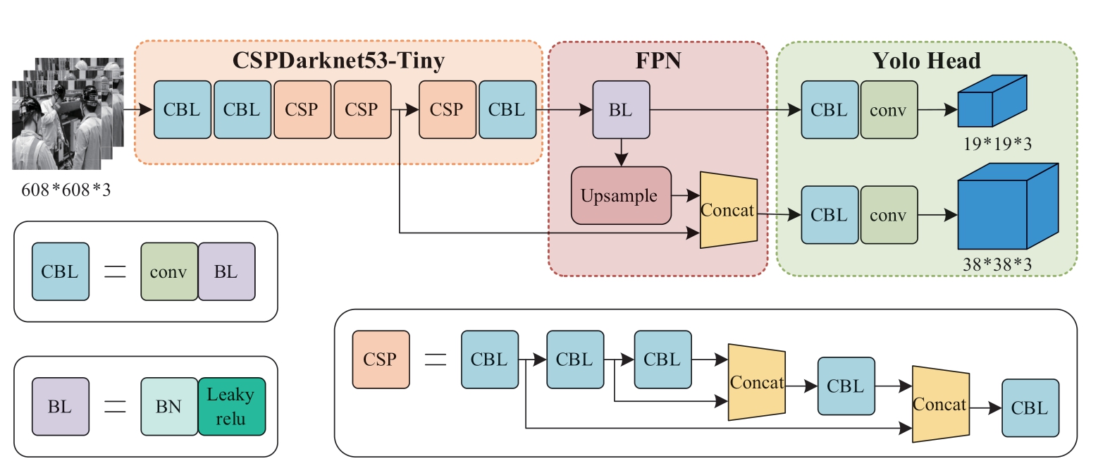
Fig.2 Network structure of YOLOv4-Tiny
Compared with YOLOv4, YOLOv4-Tiny significantly simplifies the network structure, the number of network layers is reduced from 370 to 76 layers, and the network parameters are reduced from 64 million to 6 million.Consequently, the detection speed of the YOLOv4-Tiny is significantly improved.
1.2 Loss function of YOLOv4-Tiny
The image is input into the YOLOv4-Tiny network and is divided into S*S grids, each with B bounding boxes, each of which includes four positions of the boxes (the horizontal and vertical coordinates of the box centroids and the length and width of the box) and confidence information.If the centroid of an object falls in a grid, that grid predicts that object.The category and the bounding box of the object in the grid are both predicted in the output prediction network Yolo head.The loss function of YOLOv4-Tiny consists of three parts, as shown in (1).
The first term is the coordinate prediction LCIoU, which is the position error between the bounding box and the ground truth.This algorithm adopts the CIoU loss function [19],and the schematic is shown as in Fig.3.
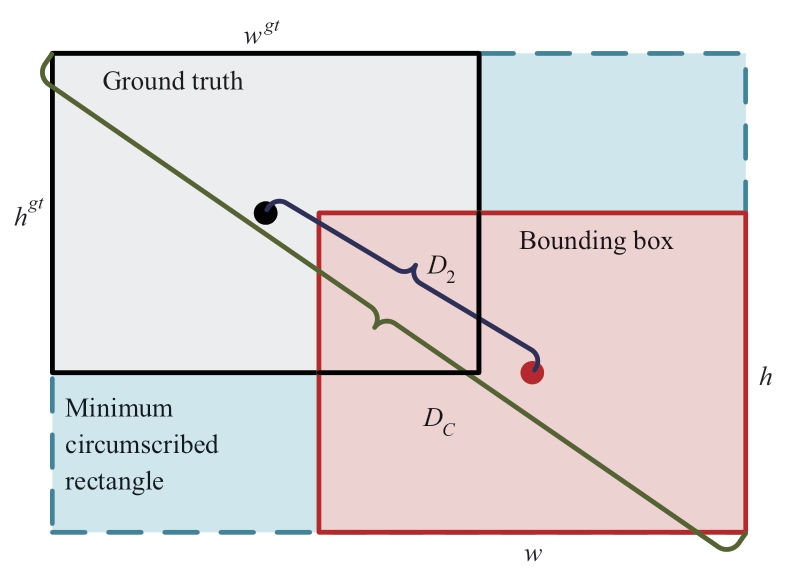
Fig.3 Schematic of CIoU loss function
The ground truth represents the real box and the bounding box represents the prediction box.
The expression of LCIoU is shown in (2).
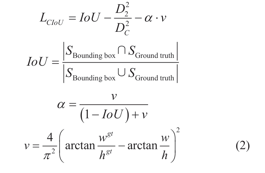
where IoU is the area ratio of the intersection and the union between the bounding box and the ground truth.SBounding box and SGround truth are the areas of bounding box and ground truth.D2 is the distance between the centroid of the bounding box and the centroid of the ground truth.DC is the diagonal distance of the minimum circumscribed rectangle between the bounding box and the ground truth.αν is the penalty term, αis the balance parameter, and ν is used to measure the consistency of the aspect ratio.ωgt and hgt are the width and height of the ground truth, respectively.ω and h are the width and height of the bounding box, respectively.From the above equation, it can be seen that the CIoU loss function works from three aspects of the overlap area,centroid distance, and aspect ratio between the bounding box and the ground truth, which enables the bounding box to approach the ground truth more quickly.
The second term is the confidence error Lconfidence, which is the confidence error between the bounding box and the ground truth.This algorithm adopts the cross-entropy loss function and the expression of the loss function is shown in (3).
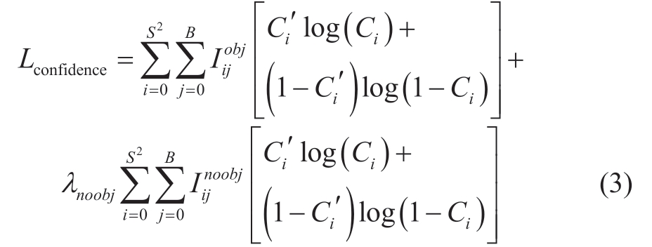
where S is the size of the grid and i represents the ith grid of the image.B is the number of bounding boxes contained in a grid, and j represents the jth bounding box.Iijobj determines whether the jth bounding box of the ith grid contains an object.If it does, Iijobj=1, otherwise, Iijobj=0.Iijnoobj determines whether the jth bounding box of the ith grid contains an object.If it does not, Iijnoobj=1, otherwise, Iijnoobj=0.Ci is the predicted value of the confidence of the ith grid.Ci′ is the true value of the confidence of the ith grid.λnoobj is the parameter of the cross-entropy loss function to reduce the weight of the loss function that does not contain the object.
The third term is the classification loss function Lclasses,which is the category error between the bounding box and the ground truth.This algorithm adopts the cross-entropy loss function and the expression of the loss function is shown in (4).

where, Iiobj determines whether the ith grid contains an object.If it does, Iiobj=1, otherwise, Iiobj=0.c is the category of the object.pi(c) is the category confidence of the ith grid.pi′(c) is the true value of category confidence of the ith grid.
The loss function of YOLOv4-Tiny converges gradually in the training process, such that the position and confidence of the bounding box are close to the ground truth.
Because the network structure of YOLOv4-Tiny is simple, it has a fast detection speed.However, owing to the reduction of the number of network layers, the feature extraction capability is insufficient and the feature utilization of the algorithm is low, which leads to a low detection accuracy of the algorithm.
2 Improved YOLOv4-Tiny algorithm
To solve the problem of low detection accuracy caused by insufficient feature extraction capability and low feature utilization of YOLOv4-Tiny, this study improves the structure of the backbone and neck networks based on the attention mechanism, and adopts optimized training methods such as transfer learning, mosaic data augmentation, and label smoothing to improve the detection accuracy of the algorithm without influencing the detection speed.
2.1 Improvement of network structure
When the convolution neural network extracts image features, the convolution kernel is convoluted with each region of the image, meaning the network pays the same attention to the features of each region of the image.However, the images or videos collected by the power system on-site work monitoring terminals have complex backgrounds and rich semantic information; thus, object detection is prone to the problems of false detection and missing detection.To obtain the characteristics of the object to be detected more accurately, special attention needs to be paid to the region of the object to be detected.Therefore,in this study, the network structure of the algorithm is improved based on the attention mechanism, by introducing the CBAM attention branch called Att1 in the backbone network and introducing ECA attention mechanism in the neck network, to increase the feature weights of the object regions and decrease the feature weights of the background regions, to improve the feature extraction capability and feature utilization.The structure of the improved YOLOv4-Tiny is shown in Fig.4.

Fig.4 Network structure of improved YOLOv4-Tiny
2.1.1 Improvement of the backbone network
Compared with YOLOv4, the YOLOv4-Tiny backbone network has a reduced number of convolutional layers and therefore a reduced feature extraction capability,leading to a decrease in the accuracy of the algorithm.CBAM [20] is a lightweight attention mechanism that can be directly embedded into the convolutional neural network architecture.It can be trained end-to-end without changing the original network structure, and does not influence the running speed of the network.Therefore, the attention branch called Att1 including CBAM is considered to be introduced into the backbone network to improve the feature extraction capability.
The principle of the convolution block attention mechanism is shown in Fig.5.CBAM consists of two independent submodules: channel attention module and spatial attention module, which perform channel and spatial attention, respectively.
Each channel of the feature map is equivalent to a feature detector.The channel attention mechanism determines which features deserve more attention, such that these feature channels occupy a larger proportion in the forward propagation process of the network, and represent important features more clearly.The network structure of the channel attention mechanism is shown in Fig.5, and the implementation process is shown in (5).
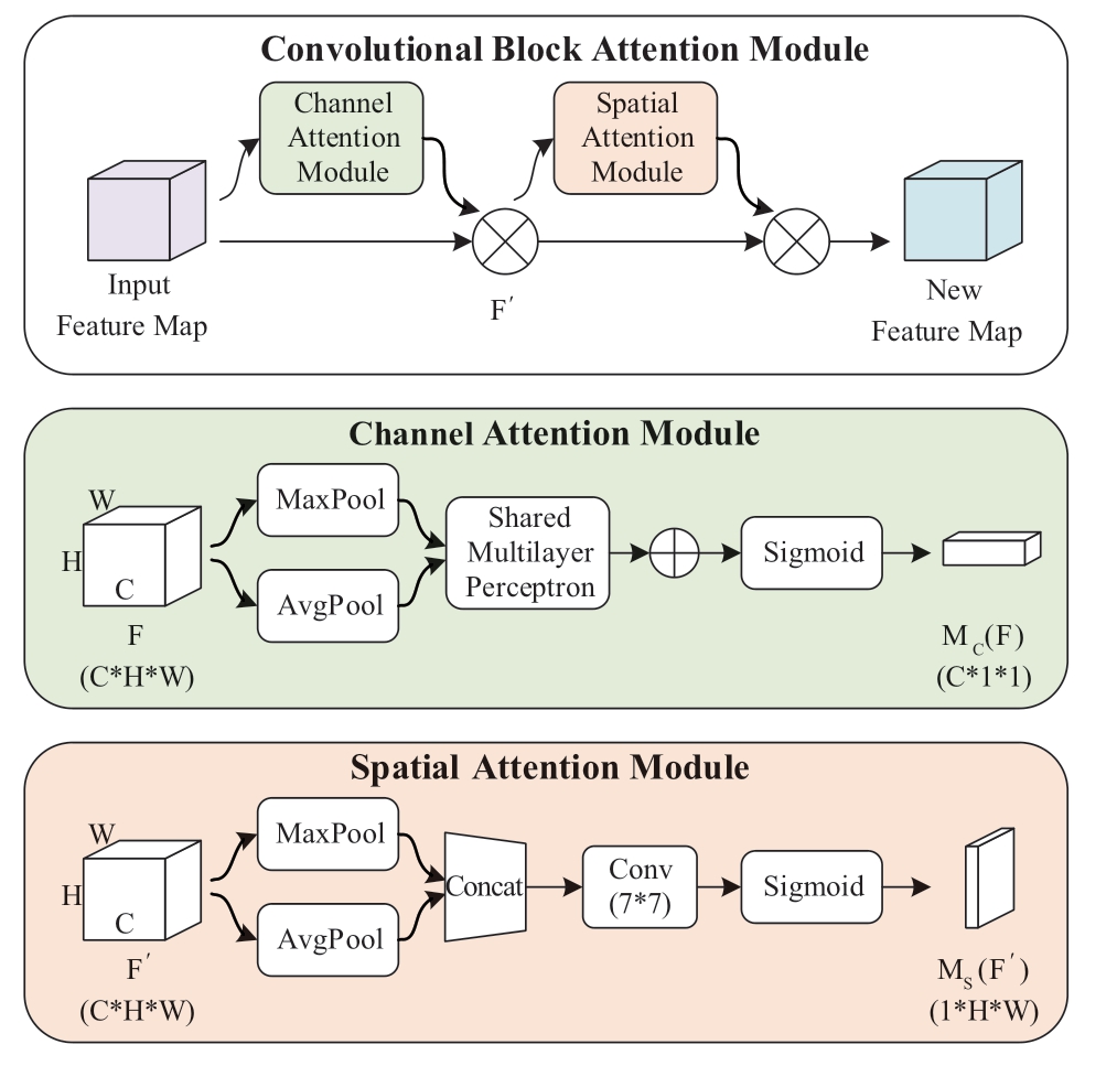
Fig.5 Network structure of Convolutional block attention module

where F is the original feature map.MC(F) is the channel attention map.Aνgpool is the global average pooling and Maxpool is the maximum pooling, which is used to characterize the global information of each channel.MLP is a multi-layer perceptron; that is, the fully connected layer,which is used to model the degree of correlation of features between channels.σ is the Sigmoid activation function to filter channel features.C, H, and W present the number of channels, height, and width of the feature map,respectively.
The main implementation steps of the channel attention mechanism are as follows.The channel attention mechanism first performs global average pooling and maximum pooling for each channel in the feature graph F to obtain twochannel descriptions of size C*1*1.Subsequently, they are sent to a two-layer shared MLP with shared weights.The number of neurons in the first layer is C/r and the activation function is ReLU nonlinear activation function.The number of neurons in the second layer is C.Finally, two features are added and the channel attention weight map MC(F) is generated using the Sigmoid activation function.The new feature map F′ is obtained by element-wise multiplication with the original feature map.The original feature map is feature optimized by the above steps to enhance the important features and suppress the irrelevant ones.
The role of the spatial attention mechanism is to obtain information on the position relationships of important features.The network structure of the spatial attention mechanism is shown in Fig.5, and the implementation process is shown in (6).

where F′ is the feature map of the attention mechanism passing through the channel.MS(F′) is the spatial attention map.Aνgpool is the global average pooling and Maxpool is the maximum pooling, which is used to obtain the global information on the channel dimensions.f 7*7 is a 7*7 convolution layer.Using a large convolution kernel can retain important spatial regional features.
The main implementation steps of the spatial attention mechanism are as follows.First, the spatial attention mechanism performs global average pooling and maximum pooling on the feature graph F′ from the channel dimension to obtain two-channel descriptions of size 1*H*W.Subsequently, the two-channel descriptions are concatenated together according to the channel dimension to obtain a feature of size 2*H*W.Finally, through a 7*7 convolution layer and the Sigmoid activation function, the spatial attention weight map MS(F′) is generated and multiplied with the original feature map element by element to obtain the feature optimized map FC.
In this study, the attention branch Att1 is added between the three CSP blocks of the backbone network.The specific network structure is shown in Fig.6.It is constructed in the form of a residual structure by combining CBAM with convolution layers.The addition of convolution layers can appropriately increase the depth of the network, thus improving the feature extraction capability.The residual structure can convert the objective function of network training from the identical mapping function H(x)=x to the residual function F(x)=H(x)-x.Compared with the identical mapping function, the residual function is easier to fit; thus,the introduction of a residual structure can easily optimize the network.Meanwhile, the residual structure can also alleviate the gradient disappearance problem caused by the increase in the layers of the neural network.
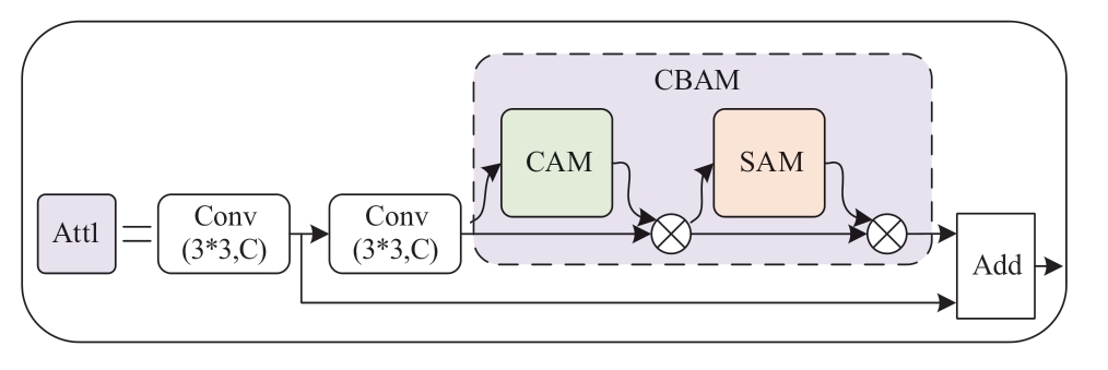
Fig.6 Network structure of Att1 attention branch
The feature map output from the CSP block is used as the input of Att1 attention branch.The major implementation steps of this attention branch are as follows.First, the global information is obtained through a 3*3 convolution layer.Subsequently, it is divided into two branches: one branch is the residual edge to retain the global information of the feature map.The other branch goes through a 3*3 convolution layer and then accesses the CBAM attention mechanism to extract important features.Finally, it is superimposed with the residual edge as the output of Att1, and this structure causes both global features and local important features of the image to converge.At this time, the amount of information of features under each channel is increased, which significantly improves the feature extraction capability of the network.The output feature map of attention branch Att1 is used as the input feature map of the next CSP block.The introduction of this attention branch increases the depth of the backbone network and effectively improves the feature extraction capability and feature utilization of the backbone network,which in turn improves the detection accuracy of the algorithm.
2.1.2 Improvement of the neck network
Compared to YOLOv4, the neck network structure of YOLOv4-Tiny is simpler, resulting in low feature utilization.
ECA [21] is an improved channel attention mechanism.General channel attention mechanisms such as SENet use a fully connected layer to obtain correlations among channel features and control the complexity of the model by dimensionality reduction.However, based on experiments,dimensionality reduction will lead to the performance degradation of the attention mechanism.The ECA attention mechanism can achieve local cross-channel interaction by one-dimensional convolution while avoiding dimension reduction.The attention mechanism has fewer parameters,can learn effective channel attention with low model complexity, and does not influence the detection speed of the algorithm to a larger extent.Therefore, an efficient channel attention mechanism is considered to be introduced in the neck network to improve the cross-channel interaction of features.The principle of ECA attention mechanism is shown as in Fig.7.
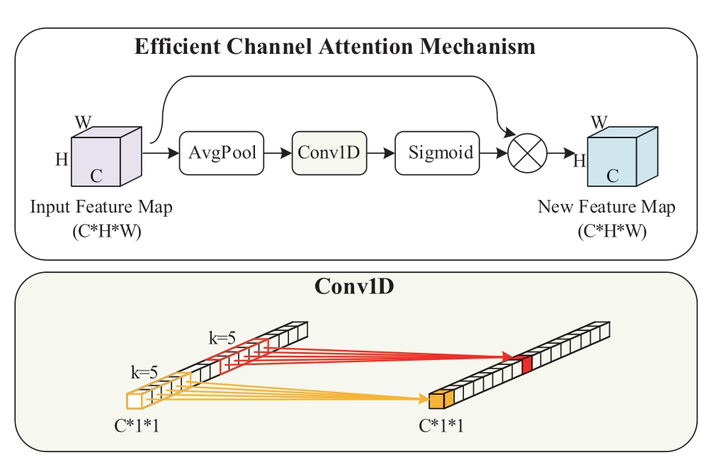
Fig.7 Network structure of efficient channel attention mechanism
The implementation process is shown in (7).

where C1D is one-dimensional convolution.k is the size of the convolution kernel, which represents the coverage of cross channel interaction, meaning how many channels in the neighborhood of a channel are involved in the attention prediction of this channel.ME(F) is the attention map of the efficient channel.
The main implementation steps of the efficient channel attention mechanism are as follows.First, the feature map F obtains the channel description of size C*1*1 after global average pooling.Subsequently, the local cross-channel interaction is realized by one-dimensional fast convolution and the coverage of interaction (that is convolution kernel size k) is obtained adaptively according to the number of channels C, as shown in (8).Finally, the attention weight map ME(F) is generated by the Sigmoid activation function,which is multiplied element by element with the original feature map to obtain the feature-optimized feature map FE.

where |t|odd represents the odd number closest to t.Generally, γ is assumed as 2, and b is assumed as 1.
In this study, ECA attention mechanism is introduced into the neck network.The specific network structure is shown in Fig.4.After the second CSP block and the last convolution module, CBL of the backbone network, two feature maps of different sizes are respectively derived as the inputs F1 and F2 of the neck network.After these two inputs, an ECA attention mechanism is added.This attention mechanism can efficiently obtain the feature correlation between channels, and adaptively adjust the feature response values of each channel to improve the utilization of features at each scale, to significantly improve the performance of the algorithm.
2.2 Optimized training methods
To improve the training effect and performance of the algorithm, To improve the training effect and performance of the algorithm, various optimized training methods such as transfer learning [22], mosaic data augmentation [16],and label smoothing [23] are used in this study.
2.2.1 Transfer learning
Transfer learning is a machine learning method that exploits existing knowledge to solve problems in different but related fields, which aims to transfer knowledge between related fields.For convolutional neural networks,transfer learning is to successfully apply the “knowledge”obtained from training on a specific dataset to a new field.Transfer learning is usually divided into feature transfer and parameter transfer.Feature transfer is the process of removing the last layer of a pre-training network and feeding its previous feature vectors into a subsequent classification or regression network for training.Parameter transfer only requires reinitializing a few layers of the network (such as the last layer), and the remaining layers directly use the weight parameters of the pre-training network and then finetune the network parameters using the new dataset.
The method of parameter transfer is applied in this study.Parameter transfer is realized by the combination of pre-training weight and freezing training, which can improve the training effect of the algorithm and accelerate the training speed of the algorithm.The specific training strategies are as follows.
1) At the initial stage of training, the weights of the backbone network are frozen to prevent the weights from being damaged.Only the weights of other parts of the algorithm are trained.The input batch size is set to 32, and the initial learning rate is set to 0.001, with 50 iterations.
2) In the later stage of training, the weights of the backbone network are unfrozen and all weights of the algorithm are trained together and the weights are adjusted.The input batch size is set to 32 and the initial learning rate is set to 0.0001.
2.2.2 Mosaic data augmentation
Owing to the limited number of sample images in the on-site work risk identification dataset, the learning method of data augmentation is considered to increase the number of sample images and thus improve the effectiveness of training.In this study, the method of mosaic data augmentation is adopted, which significantly enriches the background information of the target object by stitching multiple sample images, and can increase the batch size of the algorithm without increasing the GPU occupation.The specific implementation steps are as follows.
1) Four sample images from the dataset are randomly read at a time.
2) The four images are separately flipped, scaled, and color gamut changed separately.
3) The processed four sample images are stitched with the object bounding boxes on the top-left, bottom-left,bottom-right, and top-right of one image, respectively.The size of the stitched image is 608*608, and horizontal and vertical dividing lines are set.
4) The spliced image is processed.When the bounding box of the object exceeds the dividing line or the edge of the image, the bounding box will be removed for edge processing.Fig.8 shows the implementation process of mosaic data augmentation.
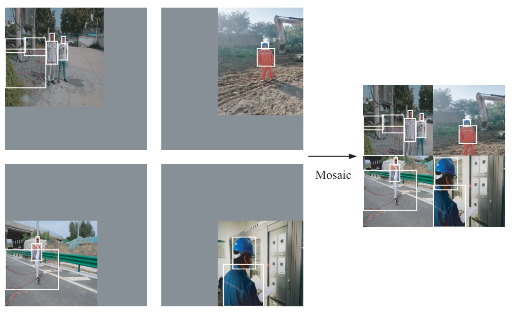
Fig.8 Implementation process of mosaic data augmentation method
2.2.3 Label smoothing
Owing to the single work and huge workload of manual labeling, incorrect labeling is prone to occur.Meanwhile, the loss function of multi-classification problems mostly adopts one hot coding, which makes the model generalization ability poor and prone to over-fitting problems.Therefore, this study uses the label smoothing method to alleviate the above problems.Label smoothing is used in the classification loss function, and the Lclasses in (4)is improved to obtain (9).

where ε is a small super parameter, and ε is generally no more than 0.01.In this study, ε is 0.01.By introducing ε to reduce the output difference between positive and negative samples, the generalization ability of the network is increased and training over-fitting is prevented.
3 Verification
3.1 Dataset
To implement on-site risk identification of power system operation, taking the dress code compliance detection as an example, the dataset on on-site work dress code compliance in the power system is constructed, including 4,980 sample images.To ensure the universality of the dataset in the onsite work of the power system, images of different operation scenarios of three majors: transmission, transformation, and distribution are collected.The dataset includes the following four label categories: wearing helmets correctly, wearing helmets incorrectly, wearing work clothes correctly, and wearing work clothes incorrectly.They are labeled as aqm,wdaqm, gzf, and wcgzf in the label file of object detection,respectively.Each image may contain multiple categories of detection objects, and more than one detection object exists in the same category.The number of each label category in the dataset is shown in Table 1.The labelimg software is used to annotate the sample images.
Table 1 Distribution of data set label categories

The dataset of the object detection algorithm is randomly divided into training set, validation set, and test set, randomly.The training set has 3,187 images, 797 images in the validation set, and 996 images in the test set.The training set is used to train the parameters of the object detection algorithm to obtain the training weights for the dataset.The validation set is used to monitor the training process and prevent training over-fitting.The test set is used to test the training effect and algorithm performance.
3.2 Hardware configuration
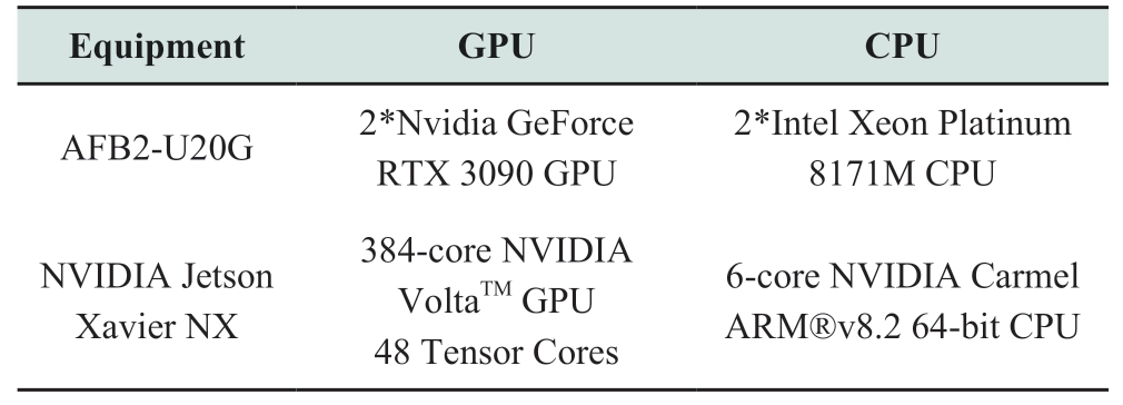
This experiment is based on the Linux 64 bit operating system, based on python 3.6 programming environment and Keras, and Tensorflow 2.2.0 deep learning framework for algorithm training and testing.The algorithm is trained in the ZFB2-U20G server and burned to edge computing equipment based on an NVIDIA Jetson Xavier NX chip for testing.The algorithm test uses a USB camera with a resolution of 1,080P and a latency of approximately 200 to 300 ms.The hardware parameters of the ZFB2-U20G server and NVIDIA Jetson Xavier NX chip are shown in Table 2.
Table 2 Comparison of hardware configuration parameters between the cloud platform and edge computing equipment
The appearance of the edge computing equipment for algorithm testing is shown in Fig.9.
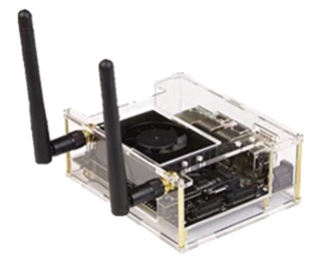
Fig.9 Appearance of edge computing equipment
3.3 Evaluation index
The evaluation indexes of this experiment include the detection speed and accuracy of the algorithm.
The detection speed is evaluated in frame per second(FPS), meaning the number of images that can be processed per second.In this experiment, a 1080p real-time video stream is collected through a USB camera.Subsequently,the video stream is transmitted to NVIDIA Jetson Xavier NX chip equipped with improved YOLOv4-Tiny.The detection speed of the algorithm can be tested by detecting the video.Generally, if the frame rate per second of the object detection algorithm exceeds 12.5 FPS, it can be used for real-time detection.
The detection accuracy is evaluated using precision(P), recall (R), average precision (AP), and mean average precision (mAP).The above indexes are obtained by detecting images from the test set.The specific principle is shown in (10) and (11).

where TP represents the number of objects correctly detected.FP represents the number of misclassified detected objects.FN represents the number of missed objects in the image.
As seen in (10) and (11), precision and recall are indicators for a certain class of objects.Precision (P)represents the proportion of the number of correctly predicted objects in all detection boxes of such objects.Recall (R) represents the proportion of the number of correctly predicted objects in all real labels of such objects.The value of average precision (AP) is the area surrounded by the coordinate axis below the P-R curve.mAP represents the average of all AP values, meaning the average value of the detection accuracy of various objects.
3.4 Experimental results of improved YOLOv4-Tiny
To verify the effect of improved YOLOv4-Tiny, in this study, Faster R-CNN (whose backbone network is VGG16),YOLOv4 (whose backbone network is CSPDarknet53,MobileNet V1, MobileNet V2, and MobileNet V3),YOLOv4-Tiny, and improved YOLOv4-Tiny are trained with the same training parameters and datasets in the ZFB2-U20G server.The above algorithms use no optimized training method during the training process.Because the image size of the dataset is large, which mostly has a resolution of 1,920*1,080, a larger network image input size is selected.The default network image input size is 608*608 if not specifically marked.After training, the test set of images from the dataset on on-site work dress code compliance in the power system are tested on edge computing equipment, equipped with an NVIDIA Jetson Xavier NX chip, to obtain the performance indexes of each algorithm.The test results are shown in Table 3.
Table 3 Performance comparison of data set detection among the improved algorithm and other algorithms
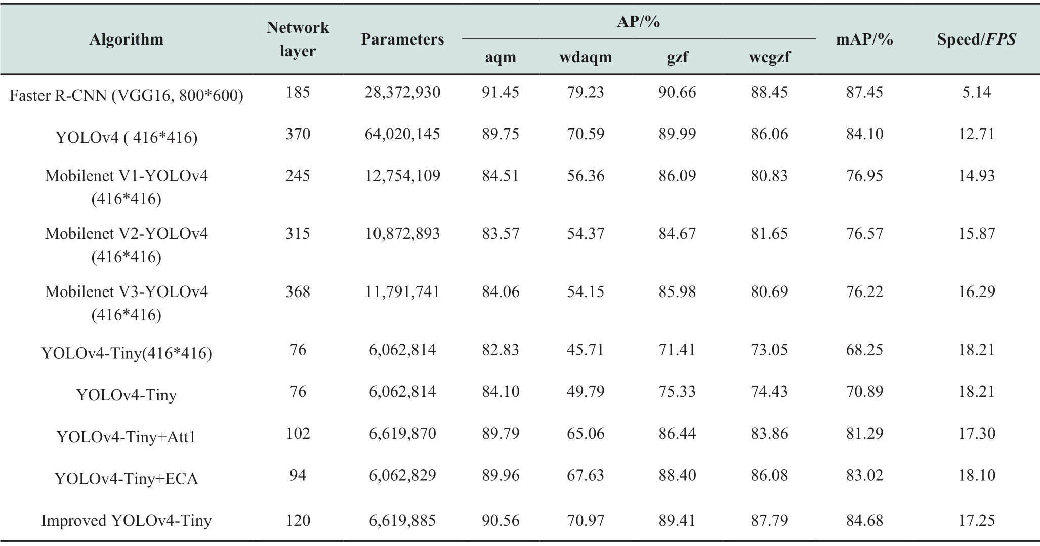
From the above table, on the NVIDIA Jetson Xavier NX chip, although the detection accuracy of the Faster R-CNN algorithm is high, the detection speed of the algorithm cannot meet the requirements of real-time detection (12.5 FPS).YOLOv4 has deep network layers and high detection accuracy; however, the detection speed is still not very high.
When detecting the on-site work dress code compliance of the power system, the detection speed of improved YOLOv4-Tiny is 235.60%, 35.72%, 15.54%, 8.70%,and 5.89% higher than that of Faster R-CNN, YOLOv4,YOLOv4 (MobileNet V1), YOLOv4 (MobileNet V2),and YOLOv4 (MobileNet V3), respectively.The number of network parameters decreased by 76.67%, 89.66%,48.10%, 39.12%, and 43.86%, respectively.The detection speed of the improved YOLOv4-Tiny reaches 17.25 FPS,and the number of algorithm parameters is only 6.6million.Therefore, improved YOLOv4-Tiny is suitable for deployment in mobile edge computing equipment.
In terms of the detection accuracy, when the image input scale is 608*608, the detection effect of YOLOv4-Tiny is better than that when the image input scale is 416*416.Through the improvement of YOLOv4-Tiny in this study,the mAP of the algorithm is improved from 70.89% to 84.68%.Figure 10 shows the comparison of the detection effects of each algorithm.The improved YOLOv4-Tiny significantly improved the detection effect of wearing helmets correctly, wearing helmets incorrectly, and wearing work clothes correctly, which verifies the effectiveness of the improved method.
In general, analysis of experimental results shows that the improved YOLOv4-Tiny can improve the detection accuracy of YOLOv4-Tiny with a small reduction in detection speed.In addition, it can be used for rapid and accurate identification of on-site work risks in power systems.
3.5 Influence of the training strategy on network performance
In this section, experiments are conducted to verify the impact of various training strategies on network performance.Three different training strategies are used to train the improved YOLOv4-Tiny.The network performance indexes under the three training strategies can be obtained from the test set, as shown in Table 4.In Table 4, TL represents transfer learning.M represents mosaic data augmentation.LS represents label smoothing.
Table 4 Performance comparison of improved YOLOv4-Tiny under different training strategies
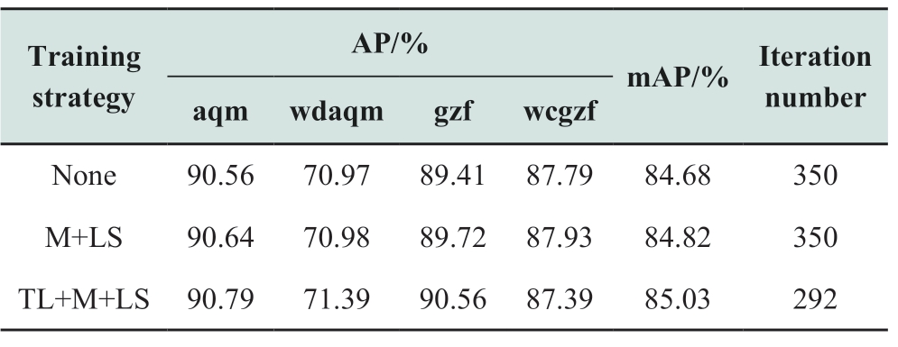
This experiment adopts the transfer learning method based on parameter transfer.The weights trained by YOLOv4-Tiny+Att1 in Section 3.4 are used as the pretraining weights of improved YOLOv4-Tiny.In the initial stage of training, the weights of the backbone network of YOLOv4-Tiny+Att1 are first transferred to the backbone network of improved YOLOv4-Tiny.Subsequently, the weights of other parts of the improved YOLOv4-Tiny are initialized, and the algorithm is iteratively trained.In the later stage of training, the weights of the improved YOLOv4-Tiny backbone network are unfrozen and all the weights of the algorithm are trained together until the end of the iteration.
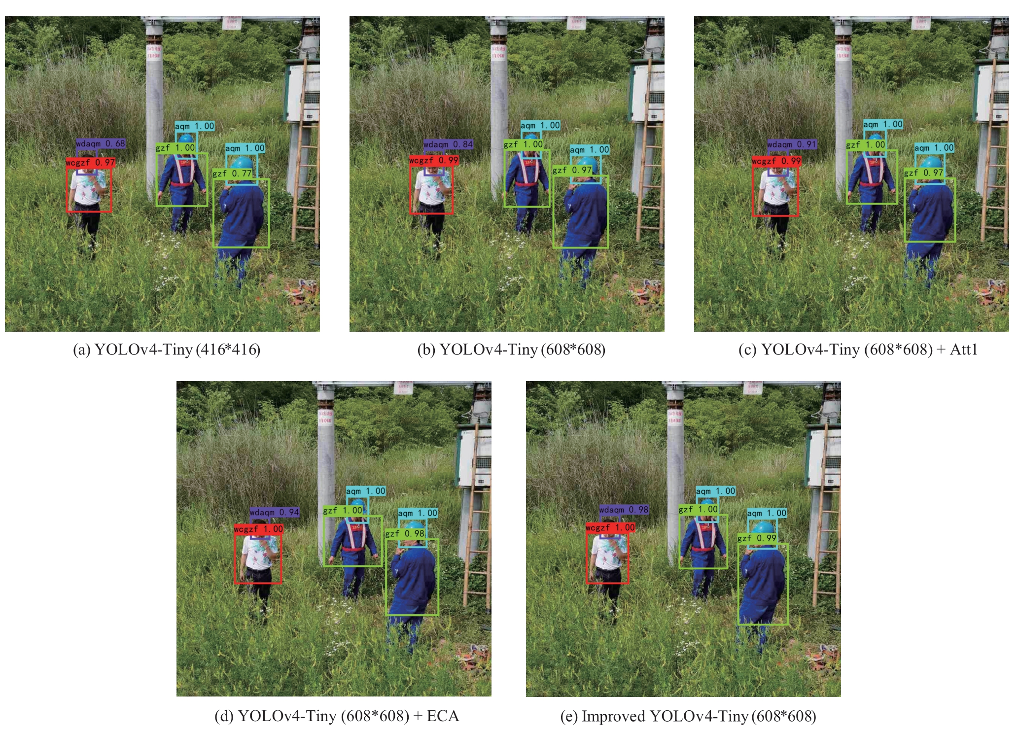
Fig.10 Performance comparison of detection effects of various algorithms
As seen from the above table, when mosaic data augmentation and label smoothing are adopted, the mAP of the algorithm improves by 0.14%.When transfer learning is adopted, the mAP of the algorithm is improved from 84.82% to 85.03%, and the number of iterations is reduced by 58.Therefore, the optimized training methods used in this study can effectively improve the training efficiency and performance of the algorithm.
4 Conclusion
Owing to the low accuracy of lightweight algorithms currently used in mobile edge computing equipment, this study proposes an improved YOLOv4-Tiny method based on the attention mechanism for real-time recognition and assessment of on-site work risks.A CBAM branch is added to the backbone network and an ECA mechanism is implemented in the neck network to enhance the feature extraction capability and improve feature utilization.In the network training process, the mosaic data augmentation method is used to increase the number of sample images,the label smoothing method is used to enhance the network generalization ability and prevent training from overfitting, and the transfer learning method is used to accelerate network convergence.The effect of the improved method is verified by experiments on detecting datasets on on-site dress code compliance in the power system field.Based on the results, the improved YOLOv4 Tiny algorithm is superior to the YOLOv4 Tiny algorithm as the mAP is increased from 70.89% to 85.03%, with a total increase of 14.14%.In conclusion, the newly proposed method can effectively improve detection accuracy and can be applied for real-time security management of on-site work in power systems.
Acknowledgements
This work was supported by the Science and technology project of State Grid Information & Telecommunication Group Co., Ltd (SGTYHT/19-JS-218).
Declaration of Competing Interest
We declare that we have no conflict of interest.
References
[1] Huang Y J (2009) Application of risk management in power security production management.Power Security Technology,11(02): 4-6
[2] Shi W S, Sun H, Cao J, et al.(2017) Edge computing-an emerging computing model for the internet of everything era.Journal of Computer Research and Development, 54(5): 907-924
[3] Viola P A, Jones M J (2001) Rapid Object Detection using a Boosted Cascade of Simple Features.Computer Vision and Pattern Recognition, Proceedings of the 2001 IEEE Computer Society Conference
[4] Dalal N (2005) Histograms of oriented gradients for human detection.Proceedings of the 2005 IEEE Computer Society Conference on Computer Vision & Pattern Recognition
[5] Felzenszwalb P F, Mcallester D A, Ramanan D (2008) A discriminatively trained, multiscale, deformable part model.Proceedings of the 2008 IEEE Conference on Computer Vision and Pattern Recognition
[6] Ren S, He K, Girshick R, Sun J (2017) Faster R-CNN: towards real-time object detection with region proposal networks.IEEE Transactions on Pattern Analysis & Machine Intelligence, 39(6),1137-1149
[7] Redmon J, Divvala S, Girshick R, et al.(2016) You only look once: unified, real-time object detection.Proceedings of the IEEE conference on computer vision and pattern recognition, 779-788
[8] Redmon J, Farhadi A (2017) YOLO9000: Better, Faster,Stronger.Proceedings of the IEEE Conference on Computer Vision & Pattern Recognition, 6517-6525
[9] Redmon J, Farhadi A (2018) YOLOv3: an incremental improvement.arXiv: 1804.02767
[10] Bochkovskiy A, Wang C Y, Liao H Y (2020) YOLOv4: Optimal speed and accuracy of object detection.arXiv: 2004.10934
[11] Liu W, Anguelov D, Erhan D, et al.(2016) SSD: Single shot multibox detetor.European Conference on Computer Vision, 21-37
[12] Wai Y J, Yussof Z B M, Salim S I B, et al.(2018) Fixed point implementation of tiny-YOLO-v2 using opencl on fpga.International Journal of Advanced Computer Science &Applications, 9(10), 506-512
[13] Yi Z, Yongliang S, Jun Z (2019) An improved tiny-YOLOv3 pedestrian detection algorithm.Optik - International Journal for Light and Electron Optics, 183:17-23
[14] Wong A, Famuori M, Shafi Ee M J, et al.(2019) YOLO nano: a highly compact you only look once convolutional neural network for object detection.Proceedings of the IEEE Conference on Computer Vision and Pattern Recognition
[15] Wang B, Le H X, Li W J, et al.(2021) Mask detection algorithm based on improbed YOLO lightweight network.Computer Engineering and Applications, 57(8): 62-69
[16] Zhou J, Xu G H, Zhu D l, et al.(2021) A fast target detection algorithm in severe road environment based on improved YOLOV4-Tiny.Journal of Signal Processing, 37(8): 9
[17] Jiang Z C, Zhao L Q, Li S Y, et al.(2020) Real-time object detection method based on improved YOLOv4-tiny.arXiv: 2011.04244
[18] Wang C Y, Liao H, Yeh I H (2019) CSPNet: A new backbone that can enhance learning capability of CNN.Proceedings of the 2019 IEEE Conference on Computer Vision and Pattern Recognition
[19] Zheng Z, Wang P, Ren D, et al.(2020) Enhancing geometric factors in model learning and inference for object detection and instance segmentation.arXiv: 2005.03572
[20] Woo S, Park J, Lee J Y, et al.(2018) CBAM: Convolutional block attention module.The European Conference on Computer Vision, 3-19
[21] Wang Q, Wu B, Zhu P, et al.(2020) ECA-Net: Efficient channel attention for deep convolutional neural networks.Proceedings of the 2020 IEEE/CVF Conference on Computer Vision and Pattern Recognition
[22] AN S J, Yang Q (2010) A survey on transfer learnig.IEEE Transactions on Knowledge and Data Engineering, 22(10): 1345-1359
[23] Müller R, Kornblith S, Hinton G (2019) When does label smoothing help? arXiv:1906.02629
Received: December 18 2021/ Accepted: March 11 2022/ Published:April 25 2022
Liang Qin
qinliang@whu.edu.cn
Kexin Li
li-kexin@whu.edn.cn
Qiang Li
liqiang@sgitg.sgcc.com.cn
Feng Zhao
feng_zhao@sgitg.sgcc.com.cn
Zhongping Xu
xuzhongping@sgitg.sgcc com.cn
Kaipei Liu
kpliu@whu.edu.cn
2096-5117/© 2022 Global Energy Interconnection Development and Cooperation Organization.Production and hosting by Elsevier B.V.on behalf of KeAi Communications Co., Ltd.This is an open access article under the CC BY-NC-ND license (http: //creativecommons.org/licenses/by-nc-nd/4.0/ ).
Biographies
Kexin Li is working towards master degree at Wuhan University, Wuhan, China.Her research interests include application of artificial intelligence in power system.
Liang Qin received the B.S.and Ph.D.degrees from Wuhan University, China, in 2003 and 2008 respectively.From 2008 to now.He is an associate professor in Wuhan University,engaged in research and development of power electronics and its application in power system.
Qiang Li received Ph.D.degree from Wuhan University, Wuhan.He is working in State Grid Information & Telecommunication Group Co., Ltd, Beijing, China.His research interests include new power system and digital transformation application under the goal of new energy, integrated energy and double carbon.
Feng Zhao received Ph.D.degree from Wuhan University, Wuhan.He is working in State Grid Information & Telecommunication Group Co., Ltd, Beijing, China.He engages in business application research and management in the field of information and communication.

Zhongping Xu received master degree.He is working in Beijing State Grid Information &Telecommunication Accenture Information Technology Co., Ltd, Beijing, China.He engages in business application research and management in the field of information and communication.
Kaipei Liu received the B.S., M.S., and Ph.D.degrees from Wuhan University in 1984, 1987 and 2001 respectively, Wuhan, China.He is currently a professor in the School of Electrical Engineering, Wuhan University.His current research interests include DC transmission and distribution, renewable energy and smart grid,power quality and data analysis.
(Editor Yajun Zou)
