0 Introduction
Modular-multilevel-converter-based high-voltage direct current (MMC-HVDC) grid has been a promising prospect enabled by the development of power electronic devices.
The HVDC system and MMC-HVDC grid have high power transmission efficiency because there is no risk of commutation failure.In addition, the MMC-HVDC grid can decouple the control of active and reactive power and integrate large-scale renewable energy sources [1-3].However, a short-circuit fault in the HVDC transmission line causes a rapid increase in the fault current from the submodule (SM) capacitors, causing severe damage to the entire flexible HVDC grid.Therefore, a fast and reliable DC line protection scheme is the key to ensuring the safety of the system operation.
Traveling wave (TW) protection has been extensively studied and applied as the primary protection to identity DC line faults [4].In practical applications, the TW protection proposed by Siemens and ABB identifies internal and external faults according to the change in the TW.Although these protection schemes can quickly identify the faults, there are some defects: (1) as single-end protection, there is no such feature as fault direction identification, increasing the risk of misoperation; (2) the ability to withstand noise interference and transition resistance is weak, causing low sensitivity; and, (3) the setting of the threshold relies on the simulation, which lacks a theoretical basis.An improved TW protection was proposed using the integral value of the change of the TW to identify the faults.Although the protection improved the sensitivity, the speed of the protection was affected [5].In the multi-terminal flexible HVDC grid, the faulted zone can be identified by the difference in fault characteristics across the current limiting reactors (CLR) based on the CLR configurations at both terminals of the line.A transient-current-based boundary protection scheme was proposed in [6].The rate of change of voltage (ROCOV) and the ratio of transient voltage on CLR were used to identify faults in [7-8].However, these protection schemes rely on boundary conditions at both terminals of the line.Therefore, it is not applicable for these boundary based protection schemes if there is no CLR at either terminal.The amplitude ratio between the forward and backward voltage TW was proposed in [9].Although the protection scheme did not rely on the boundary condition, the performance was easily influenced by the nonlinearity from the control of the converter, which can cause low reliability and sensitivity.Therefore, it is necessary to study an active injection protection scheme, which is not influenced by the limitations of the boundary condition and nonlinear characteristics of the converter.
Before the large-scale development of DC transmission technology, the idea of injecting a characteristic signal to identify or locate faults was proposed.Owing to the grounding method of a neutral point through a distribution transformer with large resistance, stator grounding protection by an active injection scheme is widely used [10].Meanwhile, there are two types of active injection schemes with additional DC and AC signals [11].Currently, the most widely used schemes are the 12.5 Hz power injection protection proposed by ABB and the 12.5 Hz power injection protection adopted by Siemens and NARI, [12-13].For the AC system, the principle of line selection and location using the S-injection method was proposed in [14].This principle can be used to realize line selection and location in a small current grounding system under singlephase grounding.A fault location method based on the coupled TW theory using signal terminal line-mode data was proposed in [15].The fault location can be calculated by injecting the impulse signal into the transmission line and measuring the reflection of the impulse signal.Since power electronic devices are not widely used in these scenarios, the above schemes are all based on an additional protection element to inject the characteristic signal.
Owing to the high controllability of the MMC, the protection scheme based on the integration of control and protection is a new perspective to address the above challenges.Owing to the current limiting capability of the full-bridge MMC (FB-MMC), the protection scheme in [16] identifies the fault based on the zerocrossing characteristics of currents.However, this scheme is only applicable for a pole-to-pole (PTP) fault.Active injection protection schemes were then proposed to identify the fault by injecting characteristic signals into the line from the converter.Reference [17] proposed the injection of a square-wave signal from FBMMC in a point-to-point HVDC system.However, the requirement for selectivity in the DC grid is difficult to satisfy.An improved correlation discrimination algorithm was proposed to identify faults by injecting sinusoidal signals [18].However, this scheme requires the faultride-through capability of the FB-MMC after faults.The process expands the influence range of the fault and leads to a power outage of the entire network.Therefore, it is necessary to further study the protection scheme based on the integration of control and protection.
In this study, an active injection protection scheme based on the input impedance with a half-bridge MMC (HB-MMC) is proposed to identify the fault.The input impedance can be calculated by injecting a characteristic signal at the specified frequency and acquiring the corresponding fault information.In addition, a theoretical analysis of the input impedance for discrimination between internal and external faults is presented.The proposed protection scheme is verified using Power Systems Computer Aided Design (PSCAD).
The remainder of the paper is organized as follows.Section 1 provides the analysis of input impedance characteristics.Section 2 explains the active injection strategy of MMC.Section 3 describes the fault identification of the active injection protection scheme, and Section 4 contains the simulation results of the active injection protection schemes.Section 5 presents the conclusion.
1 Analysis of input impedance characteristics
1.1 Input impedance of uniform transmission line
In the bipolar DC transmission system, there is intercoupling between the positive and negative poles.To eliminate the impact of the intercoupling, a phase-to-mode transformation is adopted [19].The decoupling expressions are as follows:

where U1 and I1 are the line-mode voltage and current, respectively; U0 and I0 are the earth-mode voltage and current, respectively; UP and IP represent the voltage and current of the positive pole, respectively; UN and IN represent the voltage and current of the negative pole, respectively.The following analysis is based on the linemode component.
The distributed parameters of the uniform transmission line are shown in Fig.1.The time-domain response characteristics of the voltage u and current i can be expressed as [20]:

where G0 and C0 denote the parallel conductance and capacitance per unit length, respectively; R0 and L0 are the series resistance and inductance per unit length, respectively; x is the location; and, t is the time.
The circuit can be analyzed when the power supply at the beginning terminal is a sinusoidal time function of the angular frequency ω.In this case, the voltage and current along the uniform transmission line are sinusoidal time functions at the same angular frequency.Therefore, the vector method can be used to analyze the voltage and current along the uniform transmission line.

where Z0=R0+jωL0 and Y0=G0+jωC0 are the impedance and admittance per unit length, respectively.Further, it can be derived that U (x) and I (x) satisfy the wave equation:

where ![]() is the propagation constant of the uniform transmission line.By solving (4), the relationship between the voltages and currents between the beginning terminal and point at location x can be obtained:
is the propagation constant of the uniform transmission line.By solving (4), the relationship between the voltages and currents between the beginning terminal and point at location x can be obtained:

where ![]() is the wave impedance of the uniform transmission line,
is the wave impedance of the uniform transmission line, ![]() and
and  (x ) are the voltage and current at the beginning terminal, respectively.If the length of a uniform transmission line is l, the voltages and currents at the beginning and end terminals meet

where ![]() are the voltage and current at the end terminal, respectively, and Zend is the impedance at the end terminal.Therefore, the input impedance
are the voltage and current at the end terminal, respectively, and Zend is the impedance at the end terminal.Therefore, the input impedance ![]() can be expressed as:
can be expressed as:

According to (7), the input impedance is related to the angular frequency and length of the transmission line.Meanwhile, the input impedance is affected by the impedance at the end terminal.

Fig.1 Distributed parameter model of the uniform transmission line
1.2 Difference of input impedance between the internal fault and the external fault
A test system is used to determine the characteristics of input impedance for identifying the faulted zone by evaluating the difference between the input impedances of the internal and external faults The layout of a typical three-terminal HVDC grid is depicted in Fig.2, where each converter is an HB-MMC.The grid consists of two transmission lines, L12 and L23, with a length of 60 km.The detailed parameters of L12 and L23 are also shown.At a power frequency of 50 Hz, the line-mode series reactance is j0.42629 Ω/km, and the line-mode shunt susceptance is j3.098 uS/km.For analysis, the resistance and conductance can be ignored because their influence is much smaller than that of inductance and susceptance [21].The CLR (150 mH) is configured at the end of the terminal.Further details of the test grid and its parameters are listed in Table 1.

Fig.2 Diagram of the three-terminal HVDC grid
Table 1 Arrangement of channels

MMC2 is set as the converter to inject the characteristic signal into the grid.Taking protection unit M as an example, the difference between the input impedances of the internal and external faults is analyzed as follows:
1) Internal fault: With an internal fault, the impedance at the end of the terminal is short-circuited, and the distributed parameter model is shown in Fig.3.Then the expression of the input impedance is:
The phase-frequency and amplitude-frequency characteristics of the input impedance Zin are shown in Fig.4.With the increase in frequency, the input impedance alternates between inductive and capacitive.The critical point at ωip is a parallel resonance point, where the input impedance reaches the maximum.The critical point at ωis is a series resonance point, where the input impedance reaches the minimum.The interval between each resonance point is equal, and the input impedance Zin is proportional to the length l in the first inductive frequency band [0, ωip].

Fig.3 The diagram of an internal fault
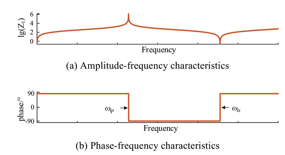
Fig.4 Input impedance in the case of an internal fault
2) External fault: With an external fault, the impedance at the end of the terminal is still connected to the transmission line, and the distributed parameter model is shown in Fig.5.Then, the expression for the input impedance is

The phase-frequency and amplitude-frequency characteristics of the input impedance Zin are shown in Fig.6.Similarly, with the increase in frequency, the input impedance alternates between inductive and capacitive.The critical points at ωep and ωes are the first parallel resonance point and the first series resonance point, respectively.The input impedance in the first lowest frequency band is still inductive.However, the first inductive band is shortened, and the interval of each angular frequency band is not equal.

Fig.5 Diagram of an external fault

Fig.6 Input impedance in the case of an external fault
A comparison of the amplitude-frequency characteristics between the cases of the internal and external faults in Fig.7 indicates that the input impedance under the internal fault is smaller than that under the external fault if the frequency is less than ω1.Therefore, in the frequency band [0, ω1], the difference in the input impedance can be the basis for fault identification.
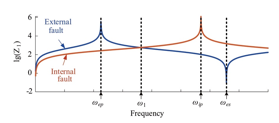
Fig.7 Comparison of amplitude-frequency characteristics between the cases of internal fault and external fault
2 Active injection strategy of MMC
2.1 Implementation of the control strategy
Owing to the high controllability of the HB-MMC, the output voltage can be controlled by inserting the designed number of SM capacitors.Therefore, a sinusoidal characteristic signal can also be generated by changing the number of SMs after a DC fault.The control strategy of the MMC is shown in Fig.8.
During normal operation, the voltage and current on the DC side can be maintained at the rated values using the classical double-closed loop control strategy.The SM capacitor voltage is uc, and the number of SM capacitors in each phase is 2N.The output voltage of the MMC is Udc, which satisfies Udc=NUc.At this time, 50% of all SM capacitors are inserted, and the system is in a steady state [22].
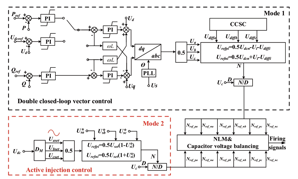
Fig.8 Diagram of control strategy of MMC
To describe the status of the SM capacitors, a variable D is defined as the proportion of the inserted SM capacitors in the total number of SM capacitors in each phase.Theoretically, the number of SM capacitors inserted in each phase ranges from [0, 2N].Correspondingly, D ranges from [0, 1].During active injection control, by changing D sinusoidally, the number of SM capacitors inserted in each phase changes sinusoidally.Therefore, a sinusoidal voltage source can be generated at a specific frequency in each phase.Meanwhile, a current at the corresponding frequency is generated in the discharge circuit.
2.2 Selection of the injection signal frequency
The input impedance characteristics are analyzed in Section 1, and the amplitude-frequency characteristics between the cases of internal and external faults are depicted in Fig.7.This indicates that the injection signal frequency should be smaller than the frequency of the intersection point ω1.For the parameters in Fig.2, ωep is calculated to be 450 Hz, and ω1 is calculated to be 737 Hz.Within the frequency band [0 Hz, 450 Hz], although the input impedance in the case of an internal fault is smaller than that in the case of an external fault, the lower frequency results in a longer injection time.Within the frequency band [450 Hz, 737 Hz], if the injection frequency is close to 450 Hz, the input impedance in the case of an external fault is too large, influencing the extraction of the fault information.If the injection frequency is close to 737 Hz, there is no difference in the input impedances between the two cases.Therefore, considering the above factors, the injection frequency is set to 600 Hz.
2.3 Selection of the injection signal amplitude
According to the above analysis, the value of D determines the output voltage of the MMC.Without additional control, D is 0.5, and half of the SMs are inserted into each phase to maintain the DC voltage.In the first few milliseconds after a fault, the output voltage is still very large.Meanwhile, the fault current rises rapidly to tens of kiloamps within a few milliseconds.MMC is easily blocked against overcurrent.Therefore, during the active injection control, D should be less than 0.5, to ensure the safety of the power electronic devices and the duration of active injection control.Furthermore, the amplitude of the injection signal should be as large as possible so that the fault information is more likely to be acquired.Therefore, D is set as a sinusoidal signal that ranges from [0, 0.5].As shown in Fig.9,a comparison of the simulation performed in PSCAD is illustrated, which is between the normal operation control and active injection control after a fault.The fault is set to occur at Bus2 in 0.8 s.Under the active injection control, the output voltage of MMC2 varies sinusoidally by changing the number of inserted SMs capacitors in each phase.Owing to the reduction in the number of SM capacitors in the discharge circuit, the fault current can be effectively limited.Meanwhile, the fault current contains an injection frequency component.
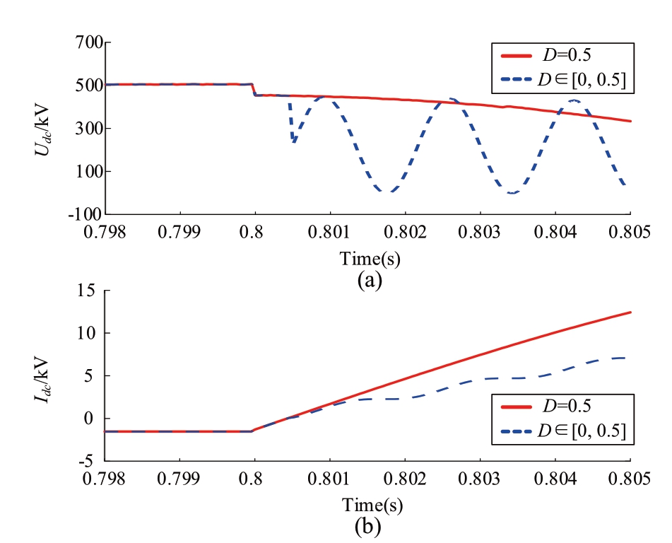
Fig.9 Diagram of control strategy of MMC
2.4 Selection of the injection signal length
To obtain the amplitude information of the injection signal, the Prony algorithm is introduced, which can directly estimate the original signal with the sum of a set of cosinoidal signal components with arbitrary amplitudes, phases, frequencies, and attenuation factors [23].The injection signal length should consider the accuracy of the algorithm estimation.If the time window is too short, data will be lost, leading to large errors in the estimation results.If the time window is too long, the calculation complexity increases, which is not conducive to online analysis.Meanwhile, the speed of protection is also affected.Furthermore, to reduce the influence of sudden changes in the measured data at the start and end of active injection control, the length of the time window should be less than that of the injection signal.Combining the above considerations, the length of the injection signal is set as 1.5 the period of the characteristic signal (2.5 ms).The length of the time window is set as 1.2 the period of the characteristic signal (2 ms), which starts 0.25 ms after the active injection control starts.
3 Fault identification of active injection protection scheme
Fault identification of the active injection protection scheme is proposed, and the process is shown in Fig.10.The interval [t0, t1] denotes the TW propagation process to the protection installation point after a DC fault occurs.The interval [t1, t2] denotes the protection activation process.The interval [t2, t3] denotes the faulted-pole discrimination process.The interval [t3, t7] denotes the process of the selected MMC to inject the characteristic signal.During the signal injection process, the fault information in [t4, t5] is acquired to identify the fault.After the protection algorithm computation process, the faulted zone is identified at t6.The test system is a three-terminal flexible HVDC grid, as shown in Fig.2.

Fig.10 Diagram of control strategy of MMC
3.1 Protection activation algorithm
The ROCOV is used to detect faults with the advantages of low computational burden, low sampling frequency, simple configuration, and fast detection speed.The criteria are as follows:
where UBus2 is the measured voltage at the line side of the CLR, and ΔU is the threshold, which should be smaller than the absolute value of ROCOV measured in the extreme case of a fault with a large transition resistance occurring at the peer terminal.Usually, the typical value of the largest transition resistance is taken as 300 Ω in a flexible HVDC grid.Therefore, ΔU is set to 3076 kV/ms with a reliability coefficient of 0.8.
The direction of the fault must also be identified.The criterion for fault direction is introduced as follows:
where UCon2 is the measured voltage at the converter side of the CLR.Owing to the boundary effect of the CLR, the direction of the fault can be identified by comparing the ROCOVs at the two sides of the CLR.If (11) is also satisfied, a forward fault is detected.
3.2 Faulted-pole discrimination algorithm
Owing to the coupling effect of the transmission lines, the sound pole may also sense a change in voltage.Therefore, the ratio of the ROCOVs between the two poles is proposed to discriminate the faulted pole:

where Ubus2P and Ubus2N represent the measured voltages at the line side of CLR and the subscripts “P” and “N” represent the positive and negative poles, respectively.kpole is the ratio of positive pole’s ROCOV to negative pole’s.Considering the disturbance of noise and the discharge of distributed capacitance, the ratio of ROCOV is not one necessarily when a PTP fault occurs.Therefore, a reliability coefficient krel1=2 is introduced.
The type of fault determines the starting strategy of active injection control.Since the protection scheme is based on a line-mode component, only one MMC in the positive or negative pole needs to start the active injection control.In this study, if a positive pole-to-ground fault or a PTP fault occurs, MMC2P in the positive pole will start active injection control.If a negative pole-to-ground (N-PTG) fault occurs, the MMC2N in the negative pole will start the active injection control.
3.3 Faulted zone identification algorithm
According to the analysis in Sections 2 and 3, the input impedance under the internal fault is much smaller than that under the external fault when the injection frequency is set to 600 Hz.As shown in Fig.11, the input impedance (Ze) is 1081.43 Ω theoretically when the external metallic PTP fault f4 occurs.Therefore, the criterion of the input impedance can be expressed as
where Uin is the amplitude of the voltage at the injection frequency, Iin is the amplitude of the current at the injection frequency, Zin is the calculated input impedance at the injection frequency, and kerl2 is the reliability coefficient, which is set to 0.8.Therefore, the threshold for the internal fault is calculated as ΔZ=kerl2·Ze=865.14.If (13) is satisfied, an internal fault is identified at the transmission line.In addition, if the calculated input impedances of protection units M and N do not satisfy (13), it indicates that there is a fault at Bus2.

Fig.11 Amplitude-fault location characteristics of input impedance
3.4 Overall scheme of proposed protection
The designed overall protection scheme based on the protection criteria described above is depicted in Fig.12.The detailed process is as follows:

Fig.12 Flowchart of the proposed protection scheme
1) Once (10) is satisfied, a fault occurs in the grid.The direction of the fault is identified using (11).
2) If there is a forward fault, then the faulted-pole is discriminated by (12).The corresponding MMC starts the active injection control.
3) The fault information is extracted and processed.Then, the values of the voltage and current at the injection frequency are acquired.
4) The input impedance of each protection unit is calculated, and the faulted zone can be identified using (13).
4 Simulation verification of the active injection protection schemes
To verify the proposed protection scheme, the test system is shown in Fig.2, and the detailed parameters are listed in Table 1.The sampling frequency is set to 10 kHz.The active injection control lasts 2.5 ms.The signal processing window is 2 ms.
4.1 Internal fault
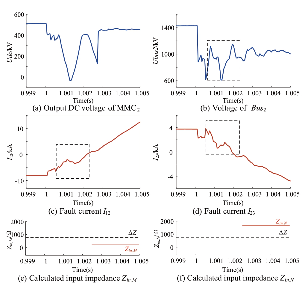
Fig.13 Simulation results of the internal P-PTG fault (f1)
Fig.13 shows the simulation results of the internal P-PTG fault f1, which is located in the middle of L12.The time of fault occurrence is 1 s.The initial TW arrives at 1.0001 s, resulting in a rapid drop in voltage Ubus2.The measured ROCOVs satisfy Equation (10).After the discrimination of the faulted poles, the MMC2P in the positive pole starts the active injection control at 1.00030 s, and the output voltage of MMC2P is shown in Fig.13(a).The fault information ofI12, I23, and Ubus2 from 1.00055 to 1.00255 s is acquired and processed to calculate the input impedance.The calculated input impedances Zin,M=Ubus2(600)/I12(600) and Zin,N=Ubus2(600)/I23(600) are 166.42 Ω and 1529.41 Ω, respectively.Zin,M is smaller than ΔZ, and an internal fault is identified at L12.Zin,N is larger than ΔZ, which indicates that there is no fault at L23.

Fig.14 Simulation results of the internal P-PTG fault (f5)
Fig.14 shows the simulation results of the internal P-PTG fault f5, which is located in the middle of L23.Similarly, after the injection control of the MMC2, the calculated input impedances Zin,M=Ubus2(600)/I12(600) andZin,N=Ubus2(600)/I23(600) are 1530.23 Ω and 165.95 Ω, respectively.Therefore, an internal fault is identified at L23.
4.2 External fault
For the backward external fault f7, the active injection control will not be activated because |dUbus2/dt| is much smaller than |dUcon2/dt|.The simulation results for the forward external P-PTG fault f4 are shown in Fig.15.The forward fault activates the injection control, and the MMC2P in the positive pole starts to inject the characteristic signal at 1.0004 s, as shown in Fig.15(a).Then the fault information of I12, I23, and Ubus2 from 1.00065 s to 1.00265 s is acquired and processed to calculate the input impedance, where Zin,M=Ubus2(600)/I12(600) and Zin,N=Ubus2(600)/I23(600) are 1059.30 Ω and 1528.17 Ω, respectively.Zin,M, and Zin,N are both larger than ΔZ.Therefore, the forward external will also not cause protection operations.
4.3 Influence of transition resistance
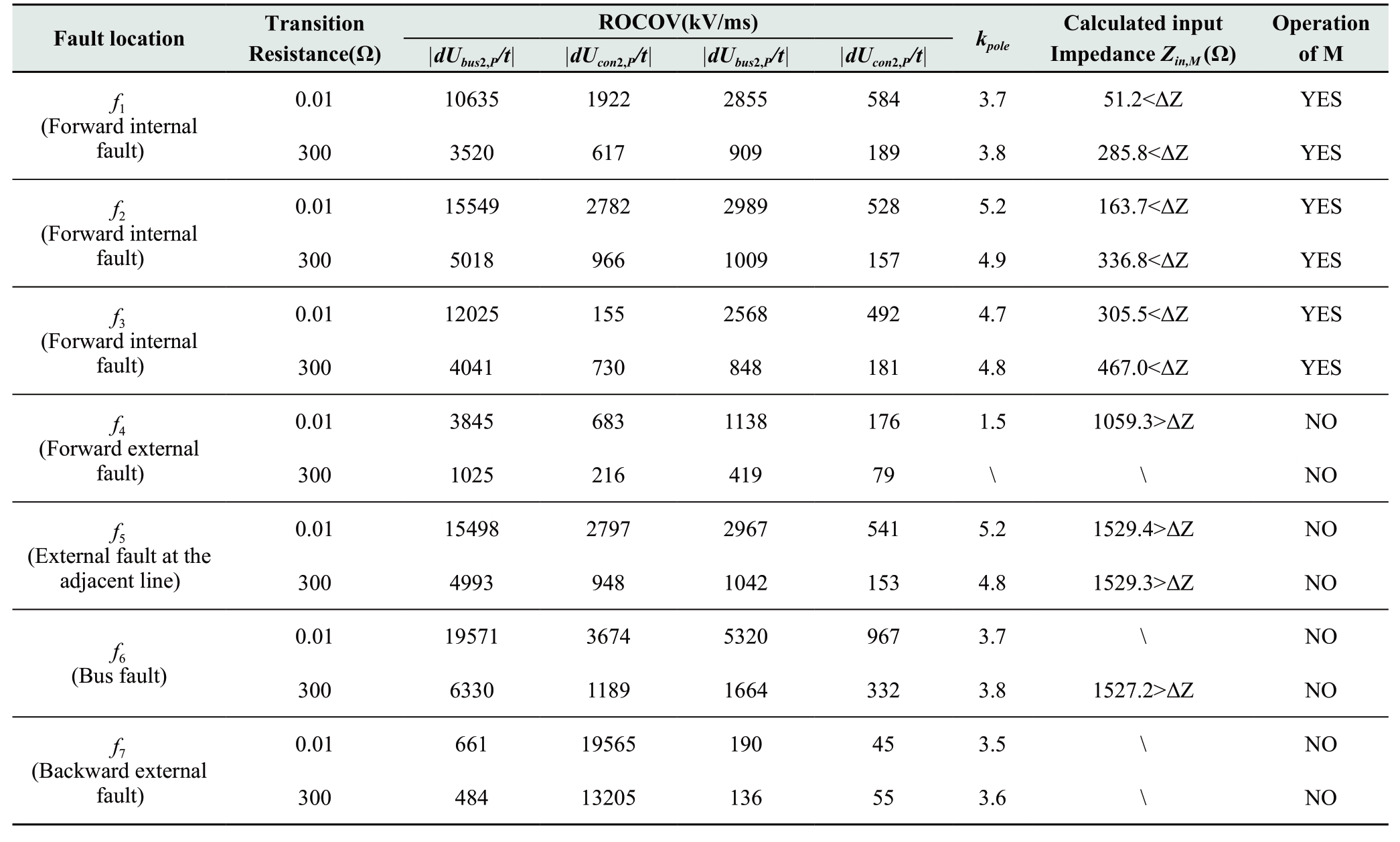
Various P-PTG faults with a transition resistance of up to 300 Ω are applied in the test system shown in Fig.2.Taking protection M as an example, the simulation results are shown in Table 2 to test the influence of the transition resistance.For the forward internal faults (f1-f3), although the transition resistance increases the calculated input impedance, the forward internal fault can still be identified.Therefore, the proposed protection scheme can endure a 300 Ω transition resistance.

Fig.15 Simulation results of the external P-PTG fault (f4)
4.4 Applicability of N-PTG and PTP faults
Based on the proposed active injection strategy and line-mode components to calculate the input impedance, the thresholds set in Section 3 are also applicable.For the N-PTG faults, kpole is smaller than 0.5, and the MMC2N in the negative pole starts to inject the characteristic signal.The calculated input impedance of the negative pole can be used to identify the internal fault.For the PTP faults, kpole is within [0.5, 2] and MMC2P in the positive pole will start to inject the characteristic signal.Since there is no influence of transition resistance, it is easier to identify the faults compared with the case of a single pole-to-ground fault.
5 Conclusion
For flexible HVDC grids, a protection scheme based on active injection of HB-MMC is proposed to realize fault identification.It can be concluded that the proposed protection scheme has the following characteristics:
1) The active injection control is constructed to inject the characteristic signal into the grid, and the rise of the fault current can also be limited.
Table 2 Simulation results of P-PTG faults with different factors
2) An analysis of the characteristics of the input impedance indicates that the input impedance under an internal fault is much smaller than that under an external fault at a specific frequency.
3) Based on the value of the calculated input impedance, a protection scheme is constructed to identify the fault zone.
4) The proposed protection scheme is verified under different situations, which are not influenced by the limitation of the boundary condition and the nonlinearity from the converter control.
In conclusion, the proposed active injection protection scheme leverages the high controllability of the power electronic device to realize fast and reliable fault identification.Compared with the traditional passive protection scheme, the proposed scheme is no longer dependent on the transient fault characteristics that disappear quickly.However, the proposed protection put forward higher requirements for signal processing capability.For the future research, the adaptability of protection in various scenarios requires further analysis.
Acknowledgements
This work is supported by the Fundamental Research Funds for the Central Universities (No.2020YJS169).The National Natural Science Foundation of China-State Grid Joint Fund for Smart Grid (No.U2066210).
Declaration of Competing Interest
We declare that we have no conflict of interest.
References
[1] Meyer C, Hoing M, Peterson A, et al (2007) Control and design of dc grids for offshore wind farms.IEEE Transactions on Industry Applications, 43(6): 1475-1482
[2] Li Y, Tang G, Ge J, et al (2017) Modeling and damping control of modular multilevel converter based DC grid.IEEE Transactions on Power System, 33(99): 723-735
[3] Adeuyi O D, Cheah-Mane M, Liang J, et al (2016) Fast frequency response from offshore multi-terminal VSC-HVDC schemes.IEEE Transactions Power Delivery, 32(6): 2442-2452
[4] He J, Chen K, Li M, et al (2020) Review of protection and fault handling for a flexible DC grid.Protection and Control of Modern Power System, 5(15): 1-15
[5] Shu H, Tian X, Dong J, et al (2011) Simulation and analyses for Yun-Guang ±800 kV HVDC transmission line protection system.Proceedings of The Chinese Society for Electrical Engineering, 31(31): 179-188
[6] Zhao L, Zou G, Tong B, et al (2015) Novel traveling wave protection method for high voltage DC transmission line// IEEE Power & Energy Society General Meeting.IEEE
[7] Sneath J, Rajapakse A D (2016) Fault detection and interruption in an earthed HVDC grid using ROCOV and hybrid DC breakers.IEEE Transactions Power Delivery, 31(3): 973-981
[8] Liu J, Tai N and Fan C (2017) Transient-voltage-based protection scheme for DC line faults in the multiterminal VSC-HVDC system.IEEE Transactions Power Delivery, 32(3): 1483-1494
[9] Tong N, Xiang X, Li C, et al (2020) Permissive pilot protection adaptive to DC fault interruption for VSC-MTDC, International Journal of Electrical Power & Energy Systems, 123: 106234
[10] Jia W, Huang S (2014) Research on the Selectivity of Statorground Fault Protection for Generators in Expanded Unit Connection.Proceedings of the CSEE, 34(28): 4941-4949
[11] Jia W, Huang S, Jiao L (2014) Stator single-phase grounding protection with double-frequency injecting source.Electric Power Automation Equipment, 34(6): 158-161
[12] COMBIFLEX generator protection.ABB
[13] Numerical Machine Protection 7UM515 Instruction Manual
[14] Sang Z, Pan Z, Ding L, et al (1997) The Principle and application of “S Injection Method” for Faulty Line Selection, 30(6): 44-4
[15] Zhong X, Li J (2012) Fault Location of Grounded Electrode Lead in HVDC System Based on The Principle of Coupled Travelling Wave
[16] Zheng T, Wu Q, Lv W, et al (2020) Protection and fault isolation scheme based on active current-limiting control for DC distribution network.Automation of Electric Power Systems, 44(5): 114-121
[17] Wang T, Song G, Hussain K S T (2019) Adaptive single-pole auto-reclosing scheme for hybrid MMC-HVDC systems.IEEE Transactions Power Delivery, 34(6): 2194-2203
[18] Hou J, Song G, Xu R, et al (2021) Single-end fault identification scheme for multi-terminal DC grid based on amplitude similarity of injection signal.International Journal of Electrical Power & Energy Systems, vol.131, pp.107091
[19] Hingorani G N (1970) Transient overvoltage on a bipolar HVDC overhead line caused by dc line faults.IEEE Transactions on Power Apparatus & Systems, 89(4): 592-610
[20] Tang L (2018) Analysis of the characteristics of fault-induced travelling waves in MMC-HVDC grid.Journal of Engineering, 2018(15): 1349-1353
[21] Wang C, Song G, Kang X, et al (2015) Novel transmission-line pilot protection based on frequency-domain model recognition.IEEE Transactions Power Delivery, 30(3): 1243-1250
[22] Sheng W, Li C, Daniel A O, et al (2018) Coordination of mmcs with hybrid dc circuit breakers for hvdc grid protection.IEEE Transactions Power Delivery, 34(1): 11-22
[23] Chaari O, Ba Stard P (1995) Prony’s method: an efficient tool for the analysis of earth fault currents in Petersen-coil-protected networks.IEEE Transactions Power Delivery, 10(3): 1234-1241
Received: September 18 2021 Accepted: November 30 2021 Published: December 25 2021
 Meng Li
mengl@bjtu.edu.cn
Jinghan He
jhhe@bjtu.edu.cn
Keao Chen
keaochen@bjtu.edu.cn
Yong Tang
tangyong@epri.sgcc.com
Ming Nie
mingnie@bjtu.edu.cn
2096-5117/© 2021 Global Energy Interconnection Development and Cooperation Organization.Production and hosting by Elsevier B.V.on behalf of KeAi Communications Co., Ltd.This is an open access article under the CC BY-NC-ND license (http: //creativecommons.org/licenses/by-nc-nd/4.0/ ).
Biographies

Jinghan He received her M.Sc.degree in electrical engineering from Tianjing University, in Tianjin, China, in 1994, and the Ph.D.degree in electrical engineering from Beijing Jiaotong University, Beijing, China, in 2007.She has been a professor with the School of Electrical Engineering, Beijing Jiaotong University since 2000.She is IEEE fellow and currently serving as a Chairman of IEEE PES China Membership Committee and a member of DC System Protection and Control Working Group under the IEEE PES China Subcommittee.Her research interests include power system relay protection, monitoring and protection of the railway traction power supply systems, DC grid and hybrid DC grid protection and control, renewable energy and smart grid.

Keao Chen received the B.S.degree in electrical engineering from Beijing Jiaotong University, Beijing, China, in 2018.He is currently working toward a Ph.D.degree at Beijing Jiaotong University.His research interests include the protection and control of VSC-HVDC transmission systems and hybrid HVDC grids.

Meng Li received the B.S.and Ph.D.degrees in electrical engineering from North China Electric Power University, Beijing, China, in 2003 and 2018, respectively.He is currently an associate professor at the School of Electrical Engineering, Beijing Jiaotong University, Beijing, China.His research interests focus on DC grid protection.

Yong Tang graduated from Fuzhou University for his Bachelor’s degree in 1982 and graduated from China electric Power research Institute for his master’s degree and ph.D in 1984 and 2002, respectively.He is fellow of CSEE.senior member of IEEE.member of Cigre.His research field includes power system simulation, power system security and control.

Ming Nie received the M.Sc.degrees in electrical engineering, in 2020, from Beijing Jiaotong University, Beijing, China, where he is currently working toward the Ph.D.degree in electrical engineering with Beijing Jiaotong University.His research interest focuses on dc grid protection and control.
(Editor Yanbo Wang)
