
1 Introduction
The protection devices of a conventional substation are usually installed in a control or protection room and use direct sampling and tripping via electrical cables. The distance between the primary and secondary equipment results in longer cables, which present some problems such as current transformer (CT) saturation, multi-point grounding, crosstalk, distributed capacitance discharge, and failure in data sharing [1].
Smart substations make data sharing possible by adding intelligent electronic devices, which include a merging unit and an intelligent terminal. These process-level devices can solve the problem of long cables through nearprocess installation in the control cubicle. However, new devices and installation methods present new problems such as the following. 1) A 5–10-ms actuation time delay is added because the installation of intermediate devices(transmission, sampling, and tripping), which also reduces the reliability and quick action of the main protection and makes the grid operate at the boundary condition.2) The malfunction rate of the process-level devices is relatively high because they are installed in control cubicles of the primary equipment; thus, they operate under poor environmental condition, which affects the system reliability [2-5].
Reference [3] proposed a strategy of a smart substation with vertically integrated device design and system integration based on discrete components. This strategy integrates the functions of merging units, protection devices, and intelligent terminals in different plugins but uses the same equipment to solve the problem of complicated configuration and redundant devices.However, the integrated equipment still needs to be installed in local control cubicles because its protection grade and anti-interference ability are not better than those of conventional secondary equipment. The problems of high malfunction rate and difficulty in inspection/debugging still exist. On the other hand, although this method reduces the intermediate transmission devices,different functions are realized in different plug-ins, which causes transmission time delay and provides little response improvement.
In recent years, the development of system on chip(SoC), highly reliable protection techniques, and highly reliable connector techniques have made integrated and local design of protection devices possible [6-8]. A verticalfunction-integrated in-site line-protection scheme based on SoC is presented in the present paper. The functions of the merging units, intelligent terminal, and line protection are integrated in a single plug-in to shorten the response time,minimize the device types, and simplify the configuration.The miniaturization design supports outdoor installation.The standard connector interface realizes plug and play(PnP). The performance test and comparison analysis are discussed in the last section.
2 System architecture and design idea
We consider a 220-kV system as an example. Fig. 1 shows the in-site protection system architecture. In this system, the in-site line protection is redundant. The two set protections are independent and both are mounted outdoor with integrated main and backup functionalities.Meanwhile, each set protection has an output switch installed inside the near-process breaker control cabinet for breaker closing and opening. It has a matching operation cabinet mounted on the near-process breaker control cabinet to control the closing and opening of the breaker and the voltage switching.
By adopting the design idea of vertical integration of the function, the single device of an in-site line protection can achieve three class functions. The first class functions are as follows: analog data acquisition, data processing,and sampling value (SV) data input and output (to the same as the functionality of the merging unit). The second class function is the logic operation of the protection and communication functionality. The third class functions are the following: switch input/output (I/O) state and generic object-oriented system events (GOOSE) data transceiving (similar to the functionality of an intelligent terminal). To be more specific, the line protection applies a conventional transformer to directly generate the protection current, protection voltage, and synchronous voltage of the corresponding bay via copper cables. In addition, the line protection applies a relay to send trip and close commands and receive related information from the breaker and isolation switch, such as the breaker position, low-pressure blocking reclosing, blocking reclosing (mutual blocking of two set protections),isolated switch position, and so on.

Fig. 1 Structure of In-site line protection in substation
The in-site line protection integrates the functions of the merging unit and inputs the protection voltage and protection current (non-measurement and control of the SV) through SV network publishing. The sampling rate is 4 kHz (4000 sampling points per second), which supports the subscription of the published bus voltage (for synchronous reclosing) using a bus potential transformer(PT) subsidiary device applied for substation area protection, safety, and device stability, as well as faultwave recording and so on.
The in-site line protection integrates the functions of an intelligent terminal. It uses a GOOSE network to publish the trip/close and other state signals of the protection device and to subscribe the relative signals of the protection or control device, such as the start of breaker failure, remote tripping, remote transmission,tripping signal of the substation-area protection, safety and stability of the device, and so on.
By considering independent sampling, decoupling from protection to measurement, control, and other principles, the bus protection, measurement, and control devices do not adopt the merging unit and intelligent terminal functions of the in-site line protection.
The in-site line protection adopts a standardized interface as the design idea. By taking a 220-kV line protection as an example, three electrical connectors and one optical connector are used. The electrical connector is used to connect the DC power supply, I/O signal,AC analog signal, and other analog signals. The optical connector includes the longitudinal channel interface, SV/GOOSE interface, MMS communication interface, highavailability seamless redundancy (HSR) communication interface, debugging interface, and so on. It can support many types of substation network structures such as the unity of SV and GOOSE network + independent MMS network, “three-in-one networks” (SV, GOOSE, and MMS), bidirectional HSR looped network, and so on. The connector interface seal that employs a special processing technology meets the waterproof and dustproof demands.Different interfaces have different color rings and faulttolerant knob position designs in case of erroneous plugging. Thus, interface standardization reduces the possibility of wrong contact and wrong wiring, and eventually facilitates realization of a replacement method for secondary equipment maintenance and PnP operation.
Because a liquid crystal display (LCD) cannot adapt to low-temperature environment, the in-site line protection adopts a no-LCD design. Specifically, the design sets a smart management unit in the control center as the insite line-protection human–machine interface and uses the IEC61850 unified modeling technology to achieve interface display, control operation, configuration management, backup management, on-line protection watch and diagnosis, and other functions. This technology performs remote smart management for in-site secondary equipment.
3 Technical scheme of vertical function integration
3.1 Line-protection system analysis in smart substations
In a smart substation, the merging unit performs analog sampling, the line protection implements logic operation, and the intelligent terminal executes a trip command. Fig. 2 shows that the sampling and tripping taches are numerous. Moreover, in the data and signal transmission, a certain delay after each tach results in a time delay. To be more specific, the maximum time delay is 2 ms after the merging unit processes the sampling data. In addition, with a 2–3ms time delay due to processing inside the protection and transmission between the printed circuit boards(PCBs), the sampling delay in the intelligent protection is 5 ms more than that in conventional protection.The protection-tripping signal, including the internal transmission and packet sending, packet parsing, and execution in the intelligent terminal and other taches,leads to a 2–3-ms delay. Therefore, compared with the conventional protection, the group action time of the digital protection in a smart substation is 7–8 ms more(slightly different among different manufacturers) [9-13].

Fig. 2 Flow chart of line protection sampling and tripping in smart substation

Fig. 3 Functional schematic diagram of vertically integrated device based on discrete plug-ins
Reference [3] described the vertically integrated device scheme based on discrete plug-ins. The plugins include analog-to-digital (AD) sampling, main CPU,process-level interface, and intelligent I/O plug-ins. In Fig. 3, shows that these modules communicate with one another through a high-speed bus. The vertically integrated device reduces the processing time of the SV and trip message (GOOSE) transmission. However,compared with the conventional protection, additional repeat sampling, low-pass filtering, and plug-in mutual communication taches are present, which further delay the sampling tach by 3–4 ms.
3.2 Vertical integration of in-site line protection
According to the smart substation system architecture,the vertical integration of in-site line protection combines the line-protection, merging-unit, and intelligent-terminal functions as well as the other functions into a single PCB of the protection device. On the one hand, this scheme reduces the>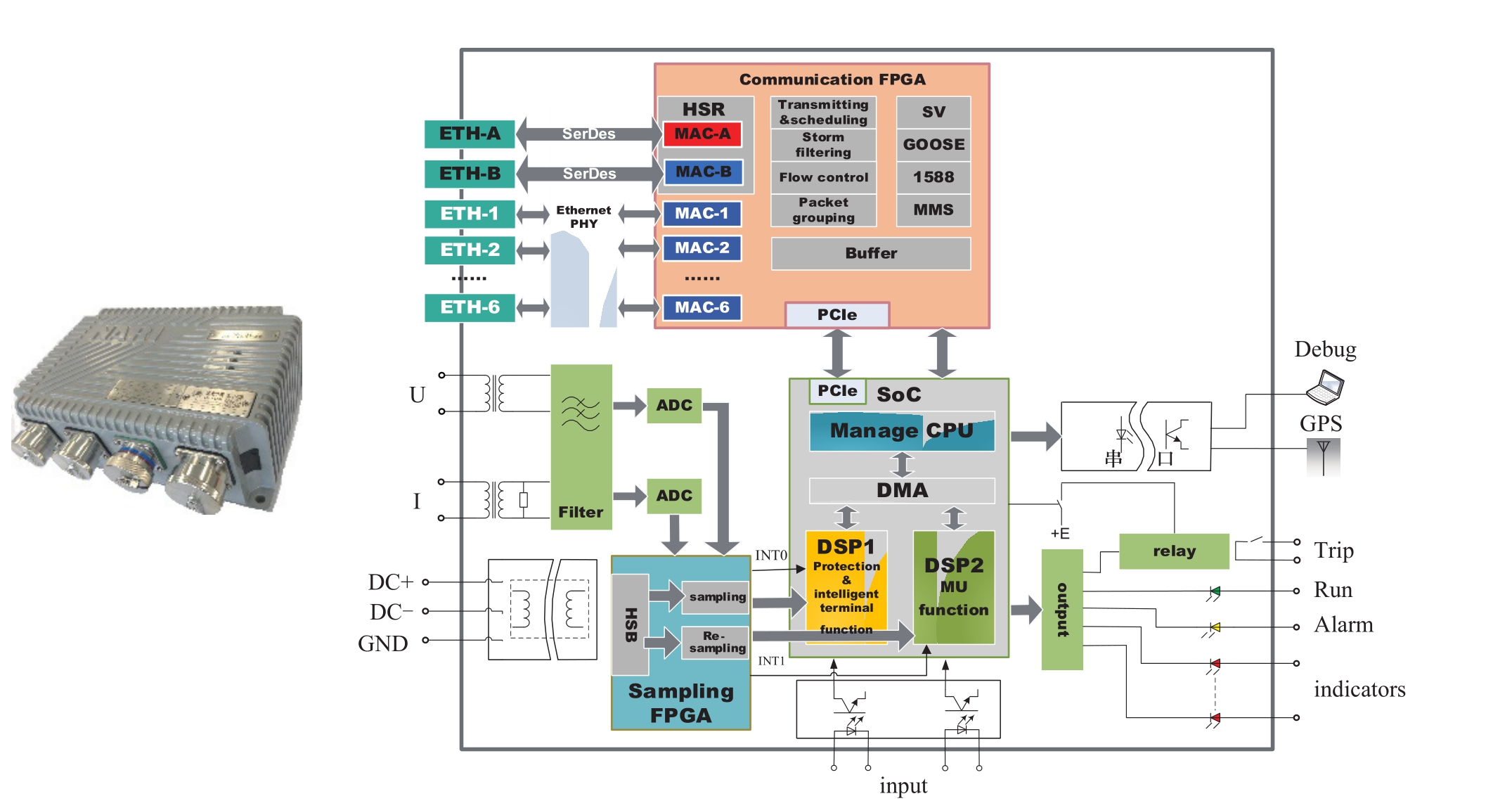
Fig. 4 In-site line protection and its function frame
The independence of the functions requires that the management, merging-unit, and intelligent functions, as well as the other functions, are distributed in separate cores.Each DSP spends different interrupt-time dispatching tasks according to the difference in the application function.The CPU management function implements device system configuration, event, wave recording, and other management functions. DSP1 implements protection and intelligent terminal functions, and one interrupt cycle(INT0) is 833 µs (1.2 K). DSP2 implements the mergingunit function, and one interrupt cycle (INT1) is 250 µs (4 K).
When the system operates, the sampling FPGA generates INT0 (1.2 K) interrupt to protect the CPU and implements 24-kHz (2400 points per second) high-speed sampling based on the INT0 interval. It also samples one datum every 20 points for CPU protection. To let the differential protections perform data synchronization on both sides of a fiber, the INT0 interval needs to be adjusted while a 24-kHz high-speed sampling interval is adjusted in real time based on INT0. The protections at both sides of the fiber realize sampling synchronization with the high-speed sampling and sampling-interrupt interval adjustment. This method needs no resampling, simplifies the calculation, and reduces the sampling delay.
The theory of the 4-kHz sampled value realization of the merging-unit function is explained by the sampling of the 24-kHz sampled data in the FPGA register and the sampling instant (the sampling interval may be real-time adjusted, but each sampling instant is recorded) in the highspeed sampling buffer. The sampling instant minus the hardware low-pass filtering delay is equal to the practical sampling instant. The sampling FPGA analyzes the external clock to achieve time synchronization of the devices and to track the external effective second pulse for the generation of the same interval 4-kHz interrupt (INT1). If no external second pulse is present, the FPGA performs an interrupt based on the internal second pulse where the interrupt interval is the secondary sampling output instant of the merging-unit function. The sampling FPGA implements Lagrange interpolation using the practical and secondary sampling instants to obtain the sampled value output by the merging unit. The sampled value is also transmitted for the application of merging-unit function module DSP2. The schematic diagram that illustrates the overall data sampling is shown in Fig. 5.
After adopting the vertically integrated technology,the sampling and tripping processes of the in-site line protection are shown in Fig. 6. On the one hand, the sampling transmission delay is as long as that in the conventional protection and is 5–6 ms shorter than that in the smart substation because software processing, internal transmission, and data sending in the merging unit as well as the SV interface handling and internal transmission in the protection are removed. On the other hand, the trip signal directly drives the trip relay through the bus, which results in the same tripping delay in the in-site protection as that in the conventional protection and in shorter delay than that in the smart substation. The reason is that the internal-tripping-signal transmission among the protective PCBs, transmission between the protection and intelligent terminals, receiving and processing in the intelligent terminal, and other processes are removed. Thus, the tripping speed of the in-site line protection is almost the same as that of the conventional protection and is 7–8 ms faster than that of the smart substation protection.
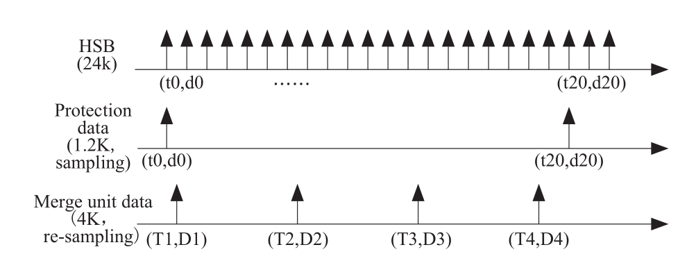
Fig. 5 Data sampling of In-site ling protection

Fig. 6 Flow of In-site line protection sampling and tripping
4 Experimental verification
4.1 Quick-action test
A 220-kV transmission line real-time digital simulation(RTDS) model for computer simulations is shown in Fig. 7.The configurations are performed based on the vertically integrated local protection of SoC, vertically integrated protection of the discrete plug-ins, smart substations, and conventional substations, to compare the performance of the in-line differential protection. The protection configurations and algorithms are consistent. The tests include internal and transformational faults. The results are listed in Table 1. The response time is from the fault occurrence to reception of the tripping in the RTDS breaker.
We can deduce from Table 1 that the tripping time of the vertically integrated in-site protection of the SoC is basically consistent with that of the conventional substation, which is 6–8 ms faster than that of the smart substation and 3–5 ms faster than that of the vertically integrated protection based on discrete plug-ins.
4.2 SV output performance test
We develop the system as shown in Fig. 8, to test the merging-unit performance. The tests include device module independence, punctuality error, re-synchronism performance, sampling response time, SV message integrity,AC analog sampling accuracy, and sampling synchronization accuracy tests. The results are listed in Table 2.
Table 1 RTDS trip time test of internal fault

Table 2 Test results of output function

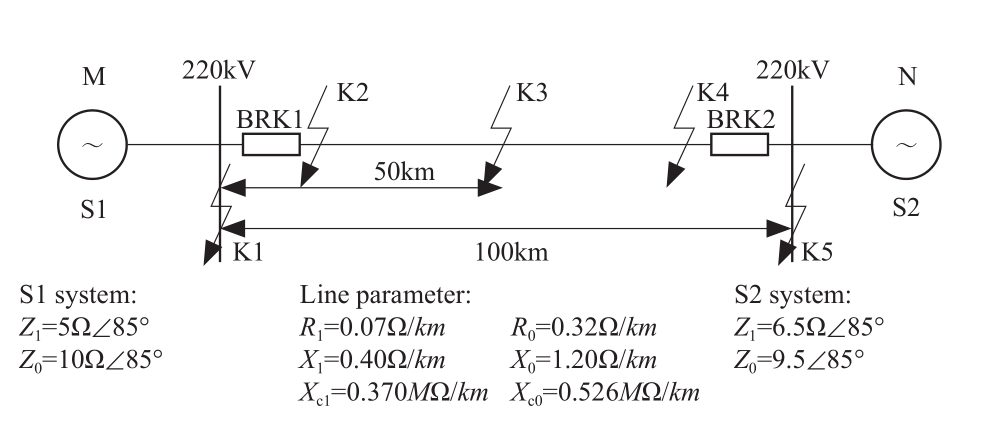
Fig. 7 220kV simulation model
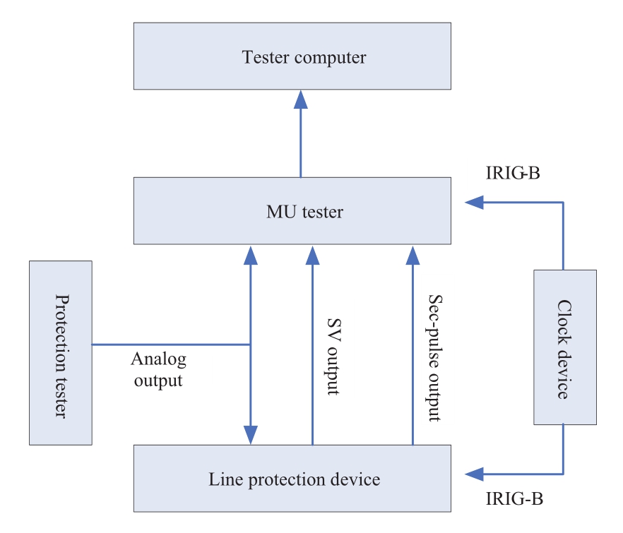
Fig. 8 Diagram of merging unit function for insite line protection
We can deduce from Table 2 that the main indicators of the merging units integrated in the in-site line-protection meet the standard.
5 Conclusions
This study focuses on line-protection problems in terms of quick action, reliability, and maintenance in conventional and smart substations. We propose a vertically integrated in-site line-protection scheme based on the SoC technique to improve line protection through integrated design,which vertically integrates the merging unit, protection device, and intelligent terminal in a single cubicle. The improvements are as follows:
1) Supports outdoor no-protection installation and shortens secondary cables.
2) Uses standard interface design and realizes PnP and replaceable inspection.
3) Realizes data sharing and provides data collection,control, support for in-station protection, and safety stabilization devices.
4) Reduces intermediate functions such as sampling and tripping, and the response time is the same as that in conventional substation and 7–8 ms faster than that in smart substation.
5) Abolishes the SV and GOOSE virtual links between the protection and merging unit/intelligent terminal to simplify the configuration.
6) Reduces the number of secondary devices, improves integration level, and reduces the device fault rate.
With the development and application of this new technique, the merging of intelligent primary and secondary equipment becomes a significant direction in smart substation development. This study proposes a vertically integrated-function in-site line-protection scheme based on SoC and aims to provide reference to future localization of secondary equipment in smart substations and the merging of primary and secondary equipment.
Acknowledgements
This work was supported by the Scientific and Technological Project of SGCC Headquarters(521101180004, Research on Outdoor Installation Protection Scheme and Key Technologies); National Key Research and Development Program of China( 2016YFB0900600).
References
[1] Tang W (2007) Protection misoperations caused by singlepoint grounding of DC circuit and AC-DC interference and countermeasures. Electric Power Automation Equipment, (09):123-125
[2] Yang Z, Zhou B, Zhang H et al (2016) Discussion on novel scheme of smart substation automation system. Automation of Electric Power Systems, 40(14): 1-7
[3] Zheng Y, Yu H, Wu C et al (2016) Application of Investigate System and Intelligent Devices in Vertical Integration Smart Substation. ZIJIN-2016 International Forum on Smart Grid Protection and Control
[4] Ni Y, Yang Y, Fan C et al (2014) Discussion on Integration of Secondary Devices in Smart Substations. Automation of Electric Power Systems, 38(3): 194-199
[5] Liu Y, Gao H, Wei X et al (2011) Design of IED with Integrated Functions of Process Level and Bay Level in Intelligent Substation. Automation of Electric Power Systems, (21): 58-62
[6] Qiu Y, Wang D, Hu C et al (2016) Application and Practice of Unprotected Outdoor Installation Protection. Power System Protection and Control, 44(20):1-5
[7] GE Multilin Incorporated (2009) HardFiber Process Bus System Reference manual
[8] Niu Q, Zhong J, Tao Y et al (2014) In-site secondary equipment protection of smart substation. Electric Power Construction,35(9): 76-81
[9] Kezunovic M., Guan Y, Guo C (2010) The 21st Century Substation Design: Vision of the Future. In: 2010 IREP Symposium-Bulk Power System Dynamics and Control VIII(IREP), Buzios, 1-6 August 2010
[10] Industrial communication networks – High availability automation networks – Part 3: Parallel Redundancy Protocol(PRP) and High-availability Seamless Redundancy (HSR) (2012)IEC. IEC-62439-3-2012
[11] Communication networks and systems for power utility automation – Part 90-4: Network engineering guidelines for substations (2013) IEC. IEC/TR 61850-90-4:2013
[12] Yang Z, Zhang H, Zhai M et al (2012) Study on control center and substation integrated monitoring and control system in smart grid. In: 2012 CIGRE Canada Conference:Technology and Innovation for the Evolving Power Grid
[13] Communication networks and systems for power utility automation – Part 8-1: Specific communication service mapping(SCSM)-mappings to MMS (ISO 9506-1and ISO 9506-2)and to ISO/IEC 8802-3 IEC 61850-8-1 (edition 2.0), 2011
Biographies
received his master degree from State Grid Electric Power Research Institute, Nanjing, China, in 2005. He is currently pursuing his Ph.D. degree of Automation of Electric Power Systems.in Hehai University. His interset is power system relay protection.

Yuping Zheng
receivedhis B. from Hefei University of Technology, Hefei, Anhui,in 1983. He
receivedhis M. from Nanjing Automation Research Institute in 1986 and Ph.D. from Wuhan University, Wuhan, Hubei,in2004. His intesest includes Power System Relay Protection and Control.

Yutao Qiu was born in Dec. 1967. He is the chief of the relay protection department in Stat grid Zhejiang electric power dispatch control center. He is the professor level senior engineer. He recently conducts the research projects on the smart substation, the outdoor installation protection and the transient protection technology.
Xiaoping Zhang, Ph.D., Professor, research fields: Power system operation and control,Flexible AC Transmission Systems, Flexible LCC HVDC, MMC VSC HVDC, Distributed Energy Systems, Energy Quality, Global Energy Interconnection, Energy Union, etc.
received his master degree from State Grid Electric Power Research Institute,Nanjing, China, in 2010. Since 2014, he has been an engineer at NARI Group Corporation,Nanjing 211106, China. His major field of interest is power system relay protection.

received his master degree from State Grid Electric Power Research Institute,Nanjing, China, in 2007. He is currently pursuing his Ph.D. degree of Automation of Electric Power Systems.in Hehai University.His major field of interest is Power System Control and Protection.
Xiaofan Hou
received her master degree from Hefei University of Technology, Hefei, China,in 2014. Since 2014, she has been an engineer at NARI Group Corporation. Her major field of interest is power system relay protection.
(Editor Ya Gao)