1 Introduction
Client-side distributed energy storage is an important field of study for the intelligent electricity industry.Intelligent technology can eliminate energy fluctuations, reducing the peak-valley load difference as well as improving the utilization rate of power supply equipment, power supply reliability, and power quality.Additionally, other prominent advantages of the new technology include enabling a clean energy supply and promoting intelligent power use.As such, cloud energy storage systems are considered an important area of study for future energy storage.At present, client-side storage devices connected to the power system present a number of challenges regarding their performance parameters and complex control.The purpose of CESS is to facilitate the aggregation of decentralized distributed energy storage equipment.However, the client-side uncertainty introduced by energy storage utilizing new communication systems means that the network security and stability is a significant challenge.
Scholars have conducted extensive practical and theoretical research into resource management for distributed energy storage systems.Yan et al.proposed the use of an energy storage system to supplement a wind power network, which used a ‘source-grid coordination’ scheduling method to assist the network when wind power predictions were not accurate [1].The researchers constructed an economic evaluation model of the energy storage system for different prediction scenarios to evaluate its ability to improve the scale of wind power to adoption.The work of Su et al.considered the coordinated operation of electric vehicles and photovoltaic energy storage in the gridconnected mode.A strategy was proposed that considered the photovoltaic active power output, energy storage state, and charging/discharging requirements of electric vehicles [2].Based on a hybrid energy storage system, Cheng et al.adopted a fuzzy control method to achieve adaptive control of the energy storage state, enabling optimal power distribution and stabilizing the power fluctuation of the photovoltaics [3].An example of research into real-time adaptive control of client-side distributed energy storage terminals is the work of Rahbari-Asr et al.[4].The study proposed a distributed method to control the operation of a network of storage devices in a smart grid.The optimal scheduling strategy for each device was achieved using only the iterative coordination between adjacent energy storage devices, without the need for a control center.Tan et al.studied the arbitrage of a distributed battery energy storage system incorporating dynamic electricity pricing, and obtained the Pareto-optimal arbitrage strategy to balance economic value and battery life cycle [5].
However, detailed analyses of the network security issues related to resource management for energy storage systems are relatively scarce in the literature.Additionally, relatively few studies exist examining the controllers that aggregate and unify various client-side distributed energy storage devices.Yang suggests that communication technology is the most important factor for networking intelligent electrical appliances, and discusses such technologies [8].Mu et al.present the design of a smart client-side system based on the smart grid that includes smart meters, smart switches, and indoor control systems [9].The studies of Tong et al.and Niu et al.compare intelligent electrical communication and interface technology [10], [11].References [14] and [15] analyze the design of intelligent electrical communication technology.All of the studies mentioned here focus on the application of the communication systems and comparisons to existing systems, failing to analyze the designs in detail from a network security perspective.
In response to the gap in the literature mentioned above, this article is focused on the architecture of the cloud energy storage platform.A design for a cloud energy storage network node controller is presented with an emphasis on complete protection of the network.The system design considers the functional division, the detailed layout of the system, and safety protection measures.The node controller was tested using client-side storage in the city of Suzhou, demonstrating the effectiveness of the device and verifying the security of the system.
2 Storage cloud and distributed energy storage node controller
2.1 Storage cloud
The client-side of the cloud based energy storage system consists of the following parts: the client-side energy storage equipment layer, the transmission layer, the energy storage cloud application management layer, and the customer service layer.The architecture of the client-side cloud-based energy storage system is shown in Fig.1.
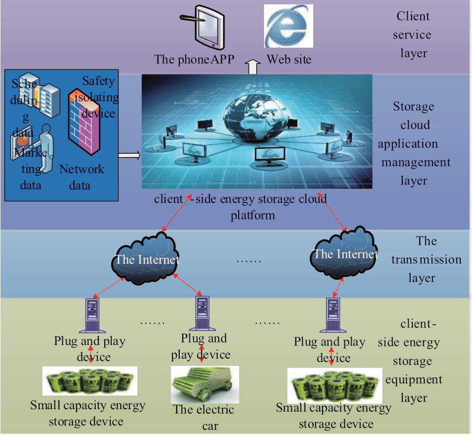
Fig.1 Schematic diagram of the cloud energy storage platform architecture showing the four component layers
The client-side energy storage equipment layer consists of storage devices, plug-and-play devices, and communication equipment.The client-side energy storage devices include the mobile energy storage of electric vehicles and the fixed energy storage of industrial, commercial, and residential users, accounting for the majority of energy storage and usage.Plug-and-play devices are a bridge for the interaction between energy storage equipment and the power grid.They perform the authentication to access the energy storage cloud network, obtain information regarding the power grid platform, and realize the control of the distributed energy storage devices at the lower level.The communication equipment connects the client side energy storage devices to the plug-and-play devices in the bottom layer of the platform architecture (seen in Fig.1).The client side energy storage device layer primarily performs function of front-end data acquisition for the cloud energy storage platform.
The transmission layer guarantees communication between the client side energy storage device layer and the energy storage cloud.The communication can be realized by multiple methods, including wired and wireless technology.At present, the platform utilizes optical, 4G, 3G, and GPRS networks as well as the energy storage cloud to realize the two-way connection of information with stable transmission performance, simple maintenance and low cost.
The management level of the cloud energy storage application is composed of sections for data acquisition, exchange, storage, platform service, and an internal network.The data acquisition section reads the data from the transmission layer and is sent through the switching section to the data storage section.The internal network sends the power grid internal dispatching and marketing data through the security isolation device to the management level of the cloud energy storage application.The platform service section integrates the underlying data and internal network data to achieve the corresponding platform services.
The customer service layer is the terminal for the energy storage service on the customer side, including a panoramic user interface and app on the customer side.It supports various forms of terminal access such as computers and mobile phones.Customers can choose energy storage services according to their needs, although the services are also managed by the cloud energy storage platform.
2.2 Distributed energy storage node controller
A distributed energy storage node controller is used to connect the public to energy storage equipment.This paper presents the design of a distributed energy storage node controller and plug-and-play device.The plug-andplay device operation includes data acquisition from the distributed energy storage device, provides the distributed energy storage device access to relevant information, executes network related control and participates as the carrier of interactive functions such as demand side response [19].The functional architecture of the plug-and-play device is shown in Fig.2.
Plug-and-play devices interact with the cloud energy storage platform, which generates control strategies by collecting internal and external data from the power grid.By accessing the web-based monitoring interface, users can access the functions of the distributed energy storage device monitoring including control strategy formulation, power grid interaction, analysis and statistics, and income queries.The plug-and-play device architecture is shown in Fig.3.
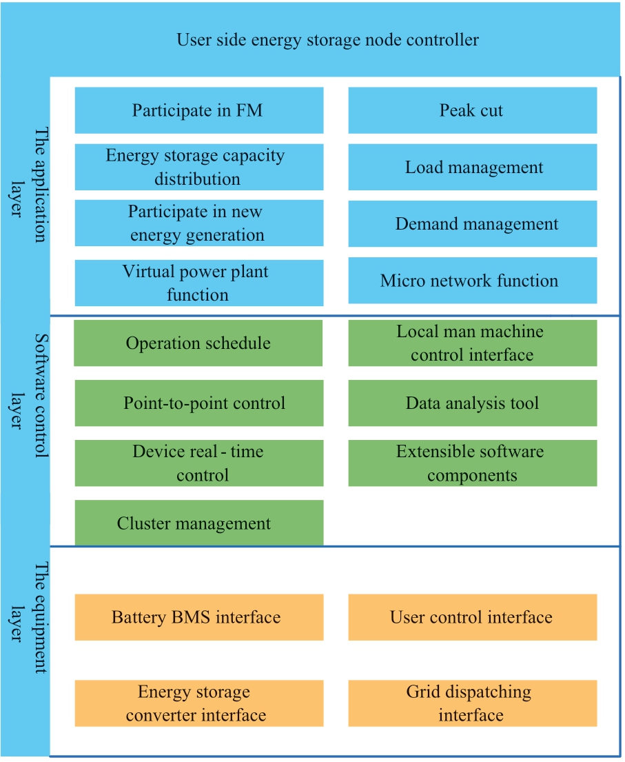
Fig.2 Functional architecture diagram of the plug-andplay device, divided into the equipment, software control, and application layers
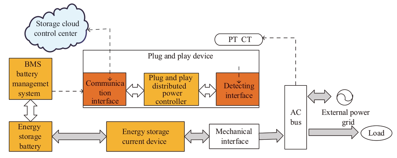
Fig.3 Plug-and-play device architecture
3 System security protection deployment
3.1 System functional analysis
At present, the primary role of the cloud energy storage system is to provide customer-side businesses with the services of orderly charging, energy storage and green energy transactions, and intelligent energy information.The system builds an open platform of intelligent energy services, providing data and service support for innovation.The overall functional architecture of the cloud energy storage service system is shown in Fig.4.
The system adopts “multi-tenancy, ecological open platform” thinking as well as the industrial Internet-ofthings (IoT), while following the “micro cloud platform and service” Internet architecture.The system uses the smart energy collection and control system as the background, the capability open center as the middle stage, and the multi-service system as the foreground.It builds a “smart background, large medium platform, and small front desk” smart energy service system to realize new energy business applications such as orderly charging and discharging and distributed energy storage.[20].
3.2 Network security deployment
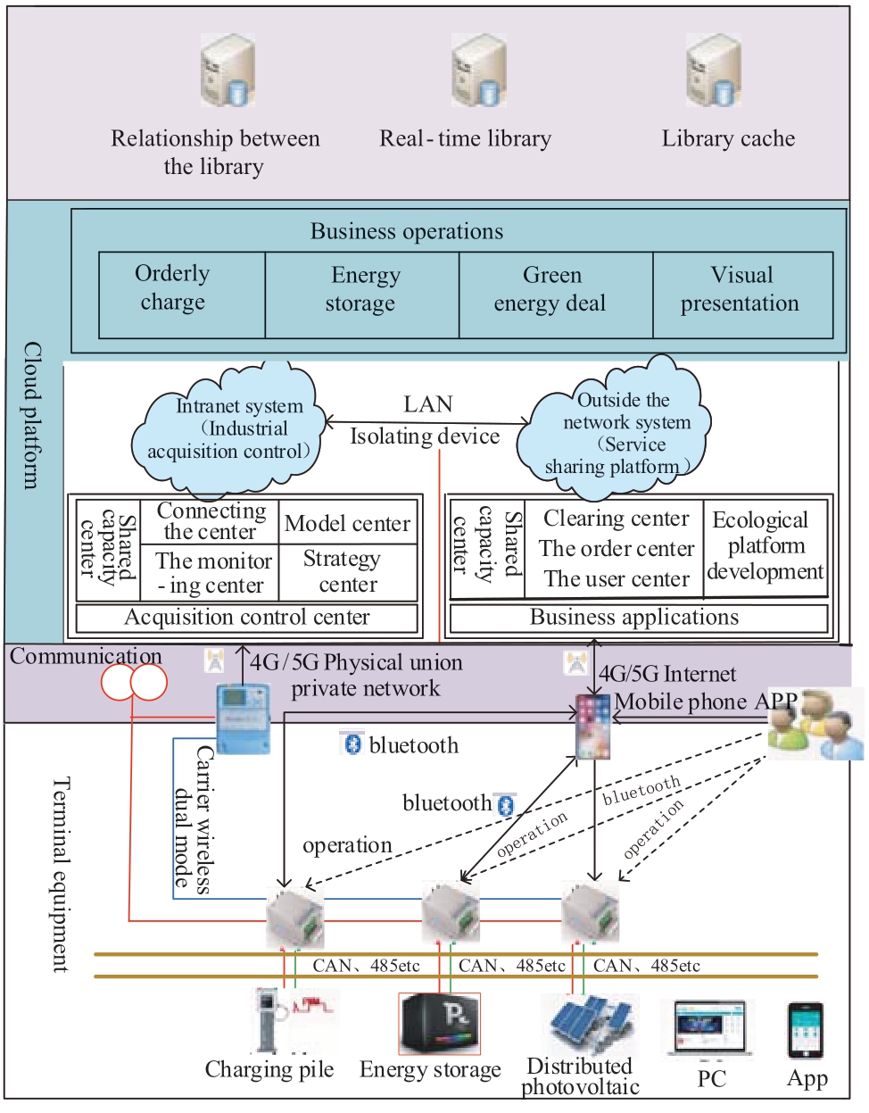
Fig.4 Overall functional architecture diagram of the cloud energy storage service system
The cloud energy storage system adopts the first-level deployment mode, which is composed of the industrial acquisition and control system of the internal network as well as the service sharing platform of the external network.At the same time, a secure access area is designated for the terminal equipment.The specific deployment procedure is as follows:
(1) Master station deployment
The industrial acquisition and control system is deployed in the three-level domain of the company’s intranet information management region.The service sharing platform is deployed in the public service domain of the company’s intranet management information region by utilizing the functional transformation of the Internetof-vehicles platform.The charging pile should be able to interact with the energy router.
(2) Terminal deployment and access mode
The energy controller is connected to the main station of the cloud energy storage system through the operator’s IoT channel and the secure access area.
(3) Ordinary personal mobile terminal app
The ordinary individual mobile terminal app uses the Internet to access the service sharing platform of the external network within the cloud energy storage system.In the case of a poor signal, it is possible to connect to the energy router via Bluetooth to initiate a business request [21].The overall deployment structure of the cloud energy storage system is shown in Fig.5.
4 Security requirements
4.1 The protective goal
In accordance with the requirements of national and corporate network security management, the goal of this paper is to ensure the cloud storage system meets the security requirements of the company[22, 23] (the Chinese standard of S3A3G3 was used as a benchmark) [insert reference here].Focus was placed on strengthening the system boundaries, network transmission, and the control class safety protection of the business.The network security measures act to prevent the proliferation and spread of security threats in the boundaries of the system, prevent transmission eavesdropping and tampering of key business data, improve the safety protections of the system, and ensure the stable and safe operation of the system.
4.2 Risk analysis
Considering that the cloud energy storage system provides services to public users, it is mainly faced with risks from terminals, networks, data, and business applications.The main security risks to the system are shown in Fig.6.
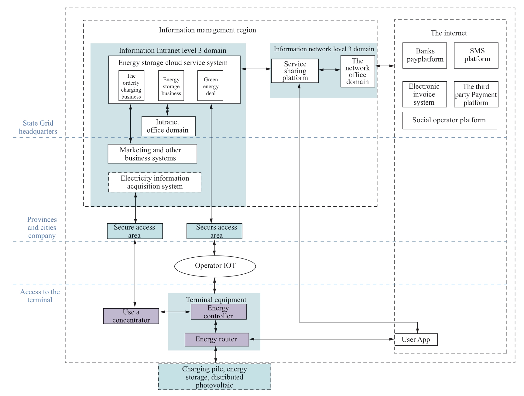
Fig.5 Deployment structure diagram of the cloud energy storage system
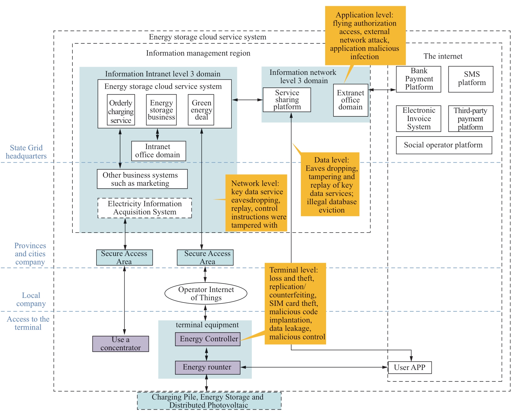
Fig.6 Risk identification diagram for the cloud energy storage system
(1) Terminal level risks
Energy controllers, energy routers and other devices are vulnerable to being stolen, lost, damaged, hardware cloned, and software copied.The devices have weak password protection and unnecessary service ports, which are easily.Mobile terminals such as smart phones are at risk from malicious code such as viruses, tampering of mobile apps and data leakage.Terminal identity impersonation threats also exist from external networks.
(2) Network level risks
The network is exposed to the risk of eavesdropping and tampering with transmitted data.Internet networks are vulnerable to nefarious attacks, wireless networks are vulnerable to interference, and data transmission may be wiretapped to enable tampering.Network equipment may be improperly configured, allowing malicious port scanning to obtain network information.Bluetooth is an open service belonging to the wireless channel in which the transmitted data may be wiretapped to perform tampering.A network level attack risks the attackers gaining access and control of energy routers [24].
(3) Data risks
In the process of data transmission, there is a risk that the interactive interface will be attacked.The transmission of the settings, control, and transaction classes may be stolen, tampered with or replayed.Storage data is also at risk of being stolen.
(4) Application level risks
The application server deployed in the extranet is vulnerable to SQL injection, cross-site scripting and other attacks through the Internet.
(5) Business level risks
The design of important business processes and business logic is not always rigorous in terms of security, exposing the transaction operations to attack and tampering.
5 System protection measures
5.1 Overall protection framework
The security protection framework of the cloud energy storage system follows the relevant national and company network security requirements.It focuses on strengthening the protection of terminal security, border security, channel security, business applications, and data security in light of the risks faced by the system [25].The system protection framework and the overall defense structure are shown in Fig.7 and Fig.8 respectively.
In terms of terminal security, the user app performs the following functions:
· Integrates an SDK that supports the security algorithm, the details of which are a Chinese state secret.
· Integrates the embedded secure access module (ESAM) chip supports the state secret algorithm in the energy controller and energy router.
· Installs the SM1 key issued by the key infrastructure of electricity information collection.
· Installs the digital certificate issued by the state grid Certificate authority (CA) for identity authentication.and conducts dynamic key negotiation.
· Secures the firmware of the terminal equipment.
The safety monitoring module is integrated into the energy router to receive monitoring data from the main station’s safety monitoring system S6000 (State grid network and information securityrisk monitoring and early warning platform).
In terms of border security, boundary division is carried out, boundaries are defined, and boundary isolation is carried out in accordance with security protection requirements.For example, an information security network isolation device is deployed between the intranet industrial acquisition and control system of the cloud energy storage system and the service sharing platform of the external network.On the side of the external network sharing platform, a type-I information network security access gateway is deployed to realize app security access.A firewall, DDoS protection, IDS/IPS, WAF and other security measures are deployed to assist in network threat prevention.The internal network security access area is set up with reference to the optimization scheme for security protection of the electricity information collection and deploy the type-I information network security access gateway.Channel security is key to ensuring the smooth flow of information, including the Bluetooth channel and gateway [26].
In terms of application security, the business password machine is deployed in the main station of the system to protect the security of the business application, particularly the authenticity and integrity of the distributed control data.The authority control is realized by the authority management module developed by the electric vehicle company and the identity identification is realized by a password and certificate.
In terms of data security, the state secret algorithm is used to protect the data transmission and storage links.
5.2 Terminal security
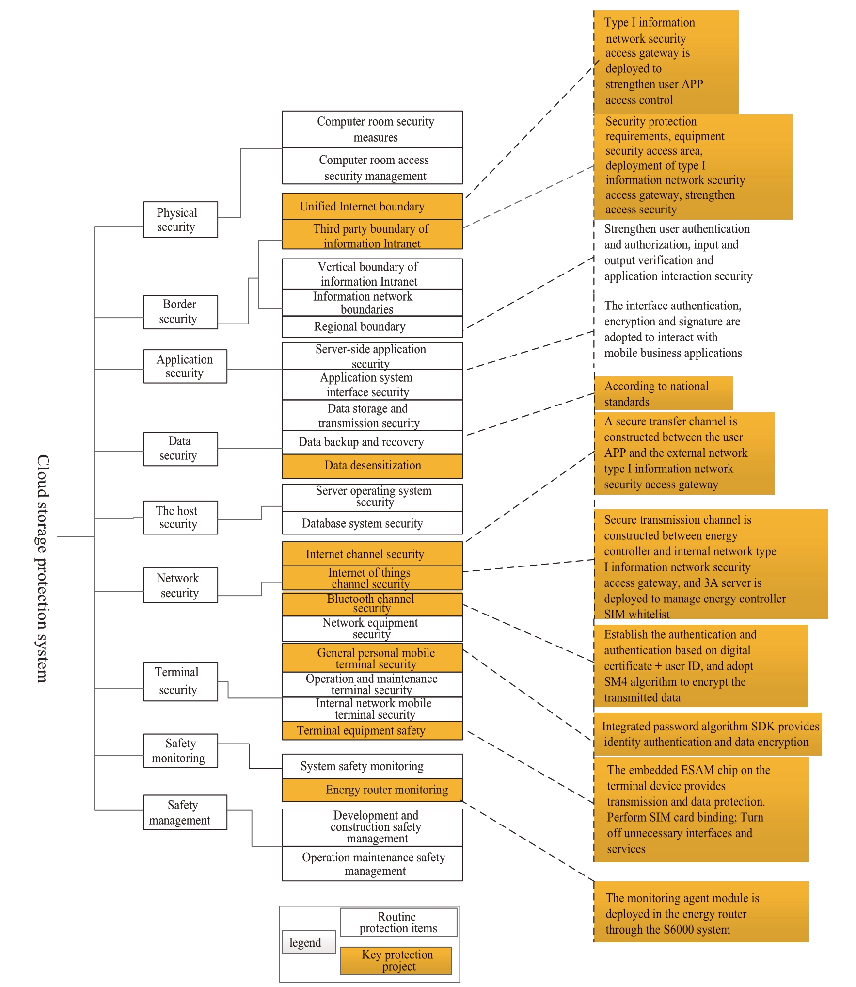
Fig.7 System protection framework of the cloud energy storage system
The cloud storage system terminal includes the internal and external network desktop office terminal, ordinary personal mobile terminal, and energy controller and energy router acquisition terminal used by the system manager.The energy controller is deployed on the low voltage side of the platform area to collect load data and provide intelligent control of the energy-using equipment on the client-side.The energy router is installed near the energyusing equipment on the customer side and serves a metering function.It enables flexible access and interactive control of such client-side energy-using equipment such as charging piles, energy storage, distributed photovoltaics, heat storage, and heating for electric vehicles.The relationship between the concentrator, energy controller, energy router acquisition terminal, and electricity information acquisition system is shown in Fig.9.
In terms of the office terminal security, the operation and maintenance management personnel of the cloud energy storage system use the office computer to access the industrial acquisition and control system of the intranet.They also use the office computer to access the service sharing platform of the extranet.The mobile terminals involved in the cloud energy storage service system are personal users' smart phones, tablets and other mobile terminals on which the app is installed.In order to ensure the normal operation of the app, tips about the version of the operating system and the download channels are included within the mobile app.File encryption, structure confusion and other features of the release program are adopted to ensure the integrity of the app software and prevent tampering.Encryption protection for the app software is used to prevent app decompilation.Mobile security sandbox technology is adopted to achieve reliable isolation between mobile application data and other application data on mobile terminals.Following the loss of a mobile terminal, the administrator can remotely destroy the application data on the designated device through the management module to prevent the leakage of sensitive data.
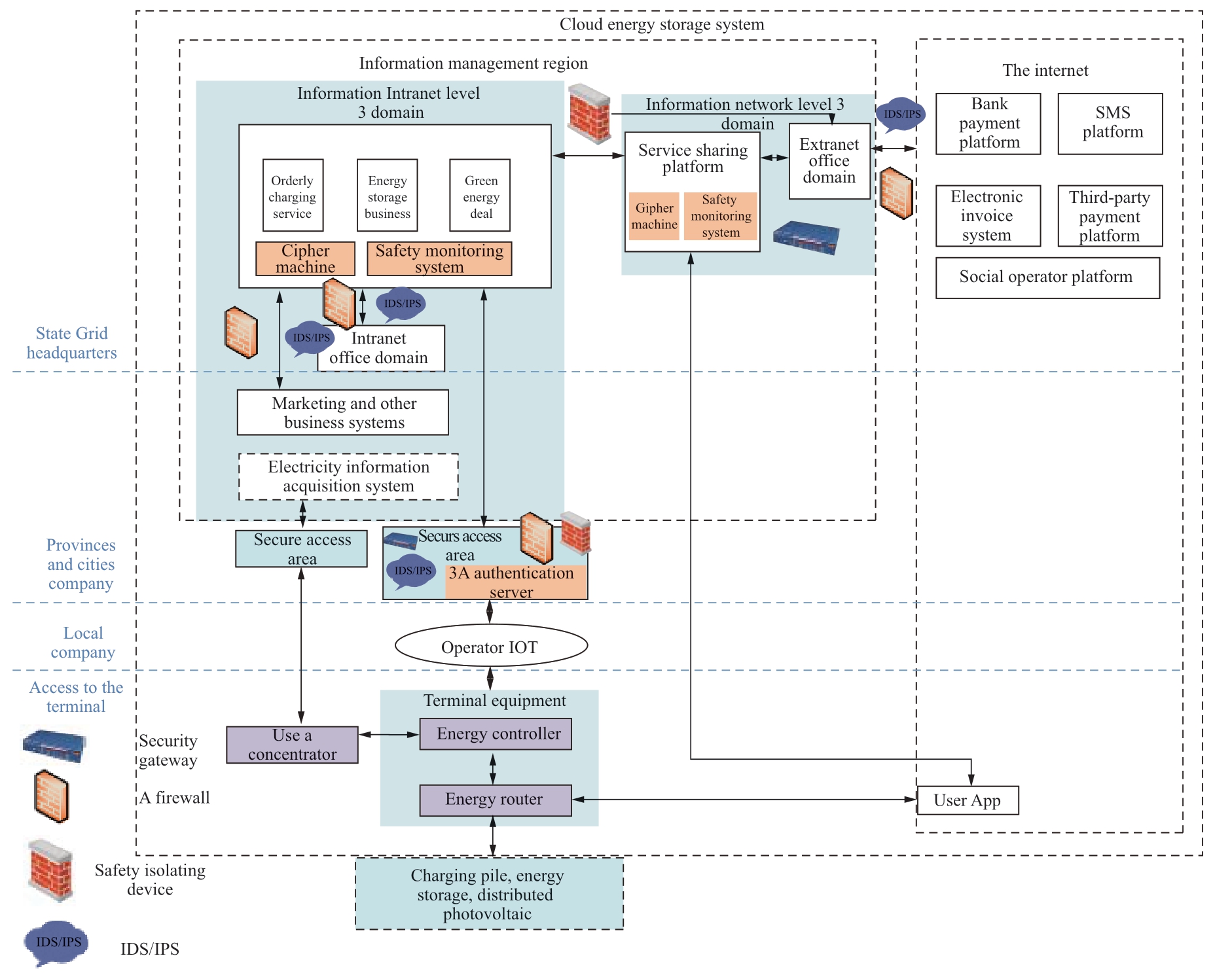
Fig.8 Overall defense structure of the energy storage cloud service system
The acquisition terminal includes the energy controller and energy router.The energy controller adopts the 4G/5G IoT channel to access the industrial acquisition and control system in the main station of cloud energy storage system through the secure access area.An RS485 communication interface is used to collect real-time load data from the station area in the concentrator.High-speed Power Line Carrier(HPLC)/micro-power wireless dual-mode communication allows interaction with the energy router to obtain user requests and metering data of the Bluetooth app sent from the energy router.The energy router uses the Bluetooth channel to interact with the user app over the Internet to obtain business user requests.A CAN or RS485 communication mode is adopted to connect with energyusing equipment for benign interactions.The independent metering module in the energy router interacts with the platform concentrator through narrow-band carrier, HPLC, and micro-power wireless communication to realize the concentrator’s acquisition of metering data.
Acquisition equipment should include the following online safety monitoring features:
· The SIM card of the energy controller application should be bound to the energy controller.
· The data interaction between the energy controller and the concentrator should be verified by ESAM.
· The metering module and the control module of the energy router have communication isolation functions.
· The data interaction between the energy controller and the concentrator is carried out by means of device authentication.
· The Bluetooth function of the energy router mainly focuses on solving the local communication problems between energy router and mobile app.
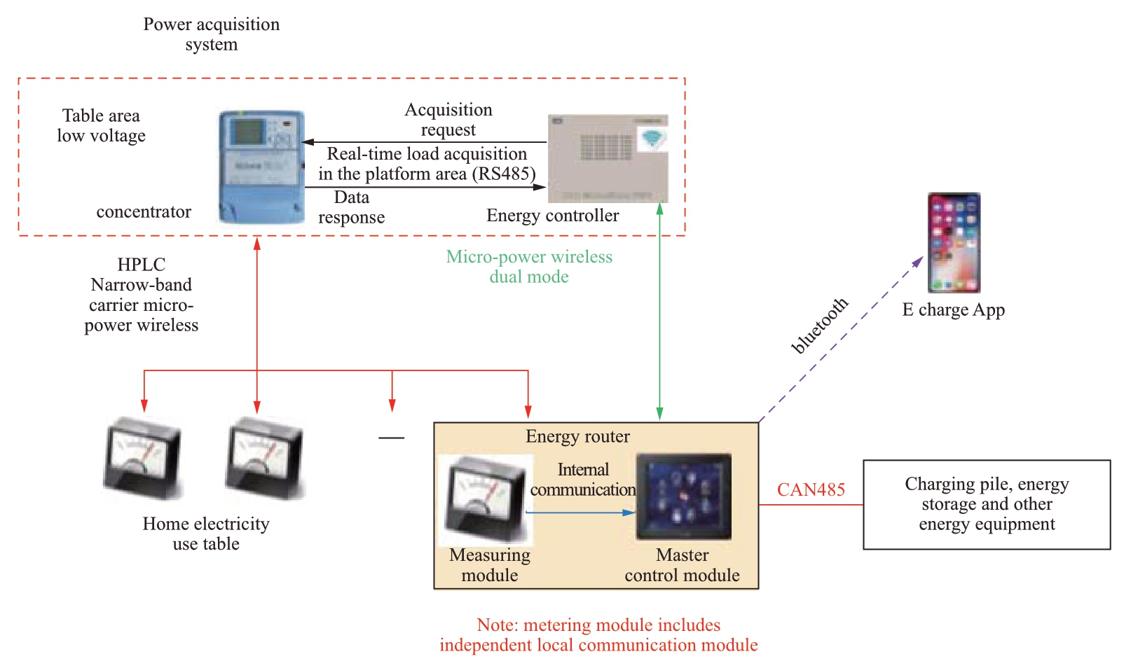
Fig.9 Relationship diagram of acquisition terminal, user app, household electricity meter, and concentrator
· The service function should be completed at the local terminal side to reduce the risk of attack.
5.3 Border security
The boundaries involved in the energy storage cloud service system are designated as: I1, the unified Internet boundary; I2, the outer network user domain boundary; I3, the outer network boundary; I4, the inner network user domain boundary; I5, the inner network vertical boundary; I6, the inner network wireless access boundary; and I7, the remaining other boundaries.The boundary layout is shown in Fig.10.
Border security includes unified Internet boundaries and deployment of secure access gateways to achieve mobile terminal access authentication and security protection.These include the deployment of logical strong isolation devices to the network boundaries; hardware firewall, IDS/IPS and other boundary security protection devices deployed at the user domain boundary and vertical boundary of the internal and external networks; and security policies such as access control, intrusion detection, logging and auditing are configured to achieve boundary isolation and security protection.A secure access zone is established at the wireless access boundary of the intranet.A secure access gateway, hardware firewall, IDS/IPS and other boundary security protection devices are deployed in the secure access area.An AAA server is deployed to control the SIM card white list of the energy controller.The energy router and the boundary of the personal mobile terminal app interact via Bluetooth to achieve identification and authentication based on a digital certificate and user ID.Session key interaction in the form of a digital envelope SM4 algorithm was adopted to ensure Bluetooth transmission security.and the energy router Bluetooth module performs database-based isolation and information interaction, integrates a security monitoring module on the energy router, and the main station S6000 performs security monitoring.
5.4 Channel security
In terms of channel security, the security of the Bluetooth channel was the focus of the design.The authentication and authorization mechanism based on a digital certificate and user ID was adopted.The SM4 algorithm was used to encrypt and protect the transmitted data.The user app and the external network type I network security access gateway conduct key negotiation through the SM2 algorithm, while the SM4 algorithm encrypts the data to build a secure transmission channel on the Internet.The energy controller and the intranet type I network security access gateway conduct key negotiation through the SM2 algorithm, while the SM1 algorithm encrypts the data to build a secure transmission channel on the IoT.
5.5 Application security
The cloud energy storage system includes an internal and external network server, acquisition terminal and mobile client business application.It focuses on strengthening the security protection of external network server application, mobile application and system indirect port.
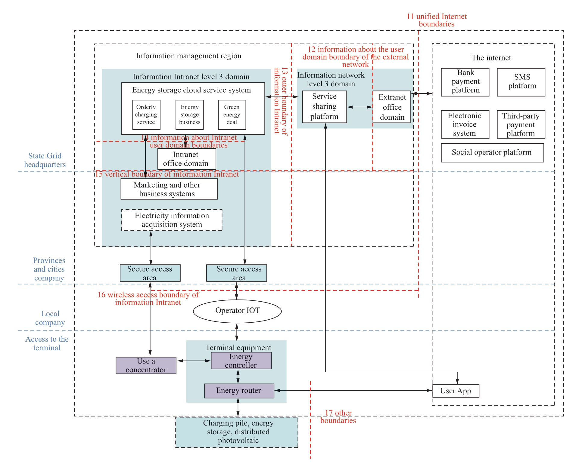
Fig.10 Boundary division of the cloud energy storage system
In terms of the mobile application security, business expansion should be carried out on the basis of apps on ordinary personal mobile terminals and new apps should not be developed.The app performs the security functions of identity authentication, password policy management, session management, software fault tolerance, application management, component security, API security, permission management, input and output management, security reinforcement, and data storage.
6 Demonstration and verification
6.1 Peak and valley filling effect of energy storage
The Langqinwan garden community in the city of Suzhou is presented as an example (there are 212 residents and 40 energy storage units installed), with the goal of peak load reduction and valley filling.The distribution capacity of the community is 1,260 kVA and the maximum load is ~250 kW.The total charging and discharging power of the energy storage equipment is ~90 kW and the permeability of the energy storage installation (the total charging and discharging power of the energy storage as a proportion of the maximum load) is 36%.The load curve before and after the installation of energy storage in the community is shown in Fig.11.After the installation of energy storage, the peakto-trough error rate of the load decreased by 27.6%.The results show that the installation of energy storage can significantly reduce the load peak and valley differential rate and play a role in load smoothing.
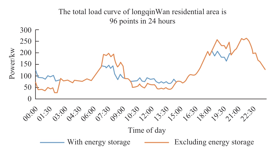
Fig.11 Typical load curve of Langqinwan residential area with 96 measurement points over 24 hours (taking peak load cutting and valley filling as the control target), showing how the installed energy storage reduces the load in peak times and increases the load in the valleys
6.2 Analysis of the impact on users’ electricity bills
Again the Langqinwan garden community was used as an example, this time using the maximum user benefit as the control target.According to the current peak and valley electricity prices for Suzhou residents, the energy storage system performs a charge and discharge cycle every day (charge: 0:00-02:30, discharge: 18:00-20:30).The load curve of the community before and after the installation of energy storage is shown in Fig.12.The results show that after installing the energy storage equipment, both individual and company users save ~5.8% of their electricity bill per day.
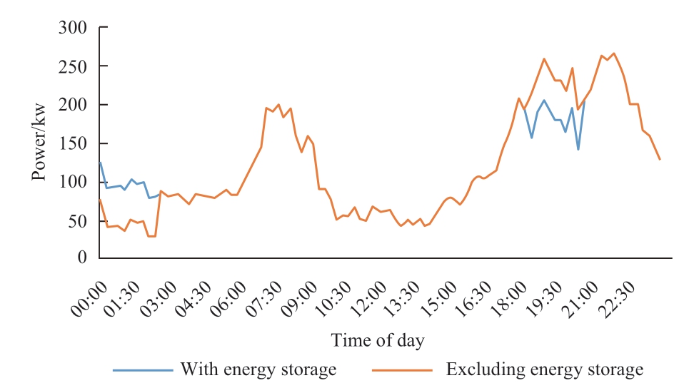
Fig.12 Typical load curve of Langqinwan residential area (with the maximum user revenue as the control target), showing reduced peak cutting and valley filling compared to Fig.11 but maximizing the user savings
6.3 Analysis of network security communication
The system alarm information may be viewed by logging in through a web page.The system alarm information browsing interface is shown in Fig.13.
7 Conclusion
As an important supporting technology for the development of the Energy Internet, energy storage has recently received increased attention and recognition.The market displays a rapid development trend, and a reasonable framework of network security for energy storage systems urgently needed.The ideas in this paper, based on the cloud energy storage platform architecture and the cloud energy storage network node controller, were designed from the perspective of complete network protection of the platform.The system presented carries out the functional division, detailed design for the system layout, and safety protective measures.Finally, through a client-side energy storage demonstration in the city of Suzhou, the effectiveness of the device and system security protection was verified.The design of a plug-and-play device for large scale application and the overall energy storage system provides the much needed network security protection.
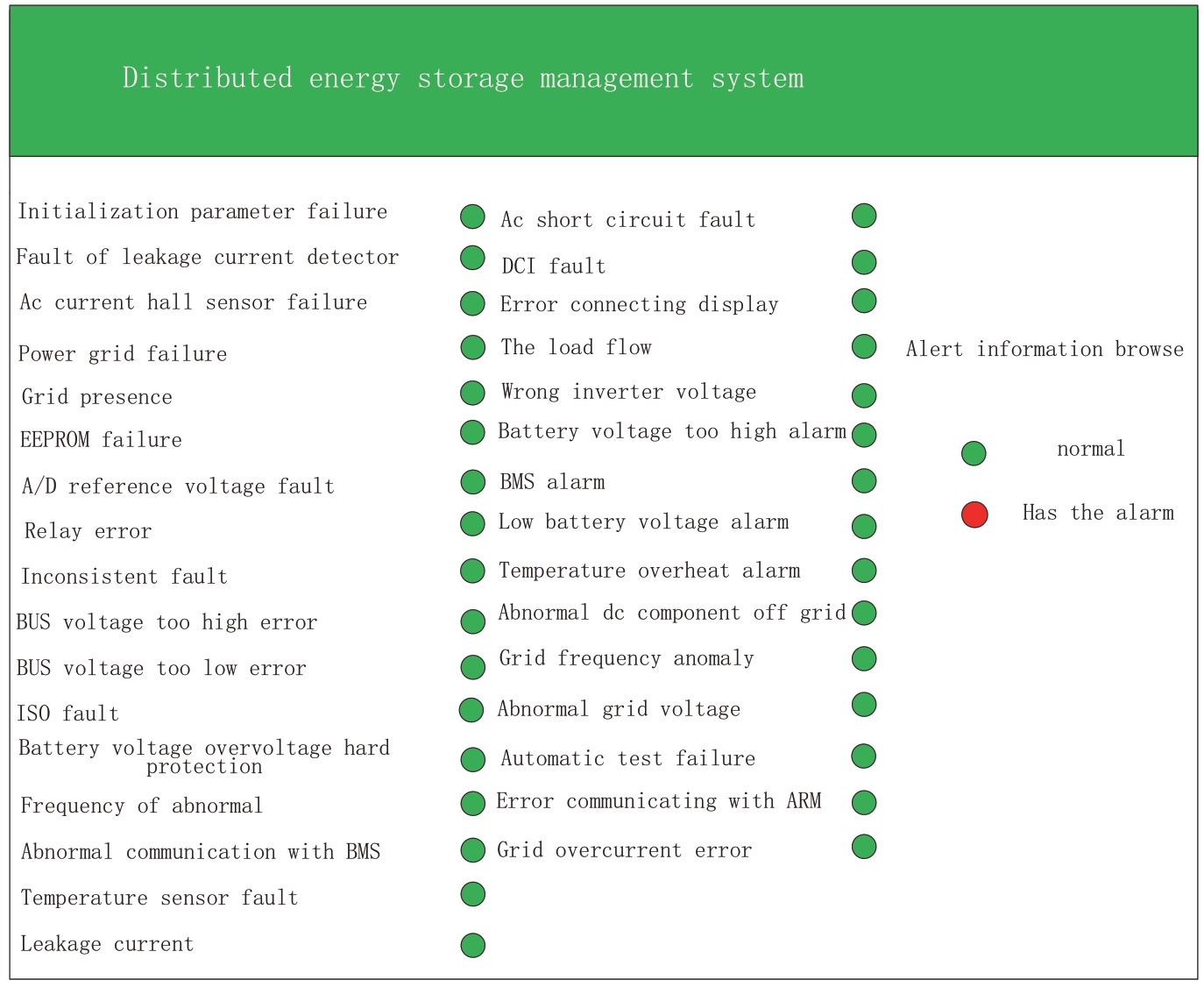
Fig.13 System warning information browsing interface, visually showing that all network communication systems are normal, demonstrating the system’s stability
Acknowledgements
This work was supported by the Technical Project of the State Grid Corporation of China (research and demonstration application of key technology of energy storage cloud for mobile energy storage application of electric vehicles 5419-20197121 7a-0-0-00).
References
[1] Yan G, Liu J, Cui Y et al (2013) Economic evaluation of using energy storage to improve the scale of wind power dispatching into the network.Proceedings of the CSEE33(22): 45-52
[2] Su S, Jiang X, Wang W et al (2015) Energy optimization management of microgrids considering electric vehicle and photovoltaic-storage energy.Automation of Electric Power Systems 39(9): 164-171
[3] Cheng Y, Tabrizi M, Sahni M et al (2014) Dynamic available AGC based approach for enhancing utility scale energy storage performance.IEEE Transactions on Smart Grid 5(2): 1070-1078
[4] Rahbari-Asr N, Zhang Y, Chow MY (2016) Consensus-based distributed scheduling for cooperative operation of distributed energy resources and storage devices in smart grids.IET Generation, Transmission & Distribution 10(5): 1268-1277
[5] Tan X, Wu Y, Tsang HK (2016) Pareto optimal operation of distributed battery energy storage systems for energy arbitrage under dynamic pricing.IEEE Transactions on Parallel and Distributed Systems 27(7): 2103-2115
[6] Bao Y, Jia L, Jiang J et al (2015) Research on the frequency control strategy of mobile energy storage for electric vehicles.Transactions of China Electrotechnical Society 30(11): 115-126
[7] Nasrolahpour E, Zareipour H, Rosehart WD et al (2016) Bidding strategy for an energy storage facility.Paper presented at the Power Systems Computation Conference (PSCC), Genoa, Italy, 20-24 June 2016
[8] Yang X (2014) Research on intelligent electrical information technology.Information Engineering 129-130
[9] Mu L, Zhu G, Zhu J (2010) Design of smart user terminal based on smart grid.Power System Protection and Control 38(21): 53-56
[10] Tong W, Liang J, Jin X (2016) Research on the development of intelligent electrical communication technology.Electrical and Energy Management Technology 1-5
[11] Niu B, Song Z, Wang J, Geng Y, Zhang Z(2017) Comparison of Intelligent Appliances Accessing Ethernet Mode and Development of Its Interface.Electrical and Energy Efficiency Management Technology (1):25-29
[12] Sun S, Yang J, Du T (2006) Intelligent electrical data communication technology.Electrical Age vol 5.pp 48-50
[13] Liu J, Wang D (2006) Comparison and Application of Intelligent Electrical Communication Interfaces.Mechanical Management Development (1): 64-66
[14] Zhang Q, Zhou C, Feng B et al (2016) Design and implementation of intelligent electrical communication system.Journal of Shenyang Institute of Engineering (12): 353-357
[15] Zhang X, Shi L (2010) Current status and development trend of smart appliances.Science and Technology Information (7): 439-441
[16] Cheng Z (2015) Research on Intelligent Electrical Appliance Information Technology.Information Technology and Informatization (1): 61-63
[17] Zhang P.Smart Grid and Intelligent Electrical System.Electrical Appliances and Energy Efficiency Management System (10): 5-9
[18] Tao Y, Zong L, Yu B, et al (2019) Research on Distributed Energy Storage Node Controller and Control Strategy Based on Energy Storage Cloud Platform Architecture.Electrical Appliances and Energy Efficiency Management Technology (02): 54-59 + 66
[19] Liu J, Zhang N, Kang C (2017) Research Framework and Basic Model of Cloud Energy Storage in Electric Power System.Chinese Journal of Electrical Engineering 37 (12): 3361-3371 + 3663
[20] Mo S, Liu T, Zeng Q, et al (2018) Research on Central Control Cloud Power Grid System Based on Cloud Energy Storage and Cloud Power Generation Technology.Sichuan Electric Power Technology 41 (04): 28-31
>[21] Zuo X (2019) Power System Service Model Based on Cloud Energy Storage.Electronic Technology and Software Engineering (14): 220-222
[22] GB17859-1999.Guidelines for the classification of computer information system security protection levels [S]
[23] GB / T22240-2008.Information Security Technology Information System Security Level Protection Rating Guide [S]
[24] Cai S, Cao Q (2018) Research on a plug-and-play distributed photovoltaic data acquisition device based on VPN encryption.Energy and Environmental Protection 40 (03): 138-143
[25] Wu M (2015) Analysis on Security Protection of University Information Service System.Computer Knowledge and Technology (11): 59-61
[26] Chen J, Wu H (2019) Research on Information Security Protection Measures of Power Network Terminal System.Digital Technology and Application 37 (10): 201-202
[27] Lu J, Shen J, Su C et al (2019) Trans-regional transmission of large-scale hydropower: problems and solutions in receiving power grid.Global Energy Interconnection 2(04): 342-350


Scan for more details
Received: 5 September 2019/ Accepted: 27 December 2019/ Published: 25 February 2020
 Qianqian Niu
18126130@bjtu.edu.cn
Tao Yan
yantao@epri.sgcc.com.cn
Jialiang Liu
jialiangl@epri.sgcc.com.cn
Jizhong Chen
chenjz@epri.sgcc.com.cn
Shaohua Xu
xushaohua@epri.sgcc.com.cn
Meng Niu
niumeng@epri.sgcc.com.cn
2096-5117/© 2020 Global Energy Interconnection Development and Cooperation Organization.Production and hosting by Elsevier B.V.on behalf of KeAi Communications Co., Ltd.This is an open access article under the CC BY-NC-ND license (http: //creativecommons.org/licenses/by-nc-nd/4.0/ ).
Biographies
Tao Yan received his Ph.D.degree in 2007 from Beijing University of Technology, China.He works at the China electric power research institute.He mainly studies the power electronics technology and the access technology of the energy storage system.
Jialiang Liu received his master degree from Huazhong University of Science and Technology (HUST), China.He works at the China electric power research institute.He mainly studies energy storage systems.
Qianqian Niu received her bachelor degree in 2018 from Shanxi University of Engineering.Her major field of interest includes power electronics.
Jizhong Chen received his Ph.D.degree from Institute of Electrical Engineering of the Chinese Academy of Sciences in 2007.He works at China Electric Power Research Institute.He mainly studies the integration, application and evaluation of large-scale energy storage technology.
Shaohua Xu received his Ph.D.degree from China Electric Power Research Institute.He works at the China Electric Power Research Institute.He mainly studies microgrid inverter control.
Meng Niu received her master degree from Beijing Jiaotong University in 2010.She is a senior engineer at China Electric Power Research Institute.She is working on configuration and integration of large scale energy storage system in power system.
(Editor Chenyang Liu)
