1 Introduction
With the development of new energy power generation technologies such as photovoltaic, there has been a gradual increase in the penetration rate of new energy sources in the field of power generation systems [1].Given the increase in new energy sources, traditional synchronous generators face challenges such as low installed capacity, lack of inertia and damping, and susceptibility to power fluctuations [2-3].To solve these issues, virtual synchronous generator (VSG) is proposed and has been widely used in distributed generation systems owing to its inertial, damping and power grid frequency regulation [4-6].Thus, employing VSG technology to a photovoltaic power generation system to design a photovoltaic virtual synchronous generator (PV-VSG) is of great significance for the development of photovoltaic power generation systems [7].
While performing maximum power point tracking (MPPT), PV-VSG provides inertia and damping support for the grid; however, its exhibits as high frequency of DCside energy exchange, which is likely to cause fluctuations in the DC bus voltage.Further, when the DC-side energy is insufficient to supply output power, the voltage is reduced, and it causes inverter failure and affects system stability.To maintain stable operation, the photovoltaic power generation system is equipped with energy storage units [8-18].The locations of these units are divided into common DC bus type, common AC bus type, and centralized type.Among these three types, the common AC bus type and the centralized type have similar structures, and the energy storage units are located on the AC side of the photovoltaic power generation system.Further, the control is simple, and each part can be controlled independently [8-14].The common DC bus type is equipped with energy storage units on the DC side, which has a certain buffer for energy exchange on the DC side.The existence of an energy bidirectional flow mechanism enables the energy exchange between the energy storage battery and the DC bus to be realized by a bidirectional DC/DC converter [15-18].
The difference in the number of variable current stages of the photovoltaic power generation system causes most of energy storage units to be located on the DC side of the power generation system; these units can be classified into single-stage type and two-stage type based on the power conversion modes.The photovoltaic module of a two-stage photovoltaic power generation system has a separate Boost converter control.The energy storage unit controls the DC side voltage, and the photovoltaic inverter implements the VSG algorithm.The photovoltaic module, energy storage unit, and photovoltaic inverter have independent functions, and the control is relatively simple.On the other hand, in a single-stage photovoltaic power generation system, the function distribution is not clear, and therefore, coordinated control is required.However, to the best of our knowledge, research on this aspect is lacking.Therefore, this paper investigates the control strategy for a single-stage PVstorage grid-connected power generation system with a common DC bus structure.
There are two main control strategies for a single-stage PV-storage grid-connected power generation system based on a common DC bus structure.Reference [15] proposes combining MPPT and VSG using the inverter.The output power of the photovoltaic module is considered as part of the mechanical power of the VSG, and the energy storage unit provides the energy required for inertia and primary frequency modulation (FM).To realize control of MPPT and VSG, the energy storage unit maintains the difference between the inverter output power and the output power of the photovoltaic module.Therefore, the energy storage unit adopts a power loop and current loop control.The control strategy implements separate control of the VSG and MPPT functions.However, the energy storage unit power reference value is the difference between the inverter output power and the photovoltaic module output power, and therefore, a communication channel is required between the inverter and the DC/DC of the energy storage unit and coordination control is more complicated.Another study proposes that the energy storage unit still maintain the power and current double loop control [16]; however, the power loop reference is changed from the indirect difference reference to the direct reference, i.e., the frequency modulation power and the inertia power is obtained by the virtual synchronization algorithm.Therefore, the sampling part of the grid side voltage is added to the hardware of the energy storage unit, and the phase locked loop and the virtual synchronization algorithm are added to the software; now, the inverter only needs to perform MPPT.The control strategy reduces the communication connection between the energy storage unit and the inverter; however, it does not reflect the damping characteristics.The reactive voltage regulation needs to be implemented by the inverter, and the function of each part is not clear.Based on the above analysis, the existing control strategy contradict between function allocation and coordinated control.Further, the MPPT function and reactive voltage regulation are realized by the inverter.The environmental factors (like temperature, light intensity, etc.) and power fluctuations caused by the MPPT algorithm will directly affect the power command, which will cause the inverter output power to exhibit fluctuations.
In view of the above problems, this paper conducts an in-depth study on the control of single-stage PVstorage grid-connected power generation system based on a common DC bus structure.A control strategy based on a virtual synchronous generator for a PV-storage gridconnected system is proposed, wherein the energy storage unit performs the MPPT algorithm, and the PV inverter performs the VSG control.This ensures that the control functions implemented by each part of the system are clear.The energy storage unit and the inverter function distribution are clear, and the requirements for coordinated control are minimized, and the output power fluctuation of the photovoltaic inverter is stabilized by smoothing the power command.
The rest paper is organized as follows.The topology and control strategy are described in section 2.Simulation results are provided in section 3.Finally, section 4 concludes the main contribution of this paper.
2 PV-storage grid-connected power generation system
2.1 Structure
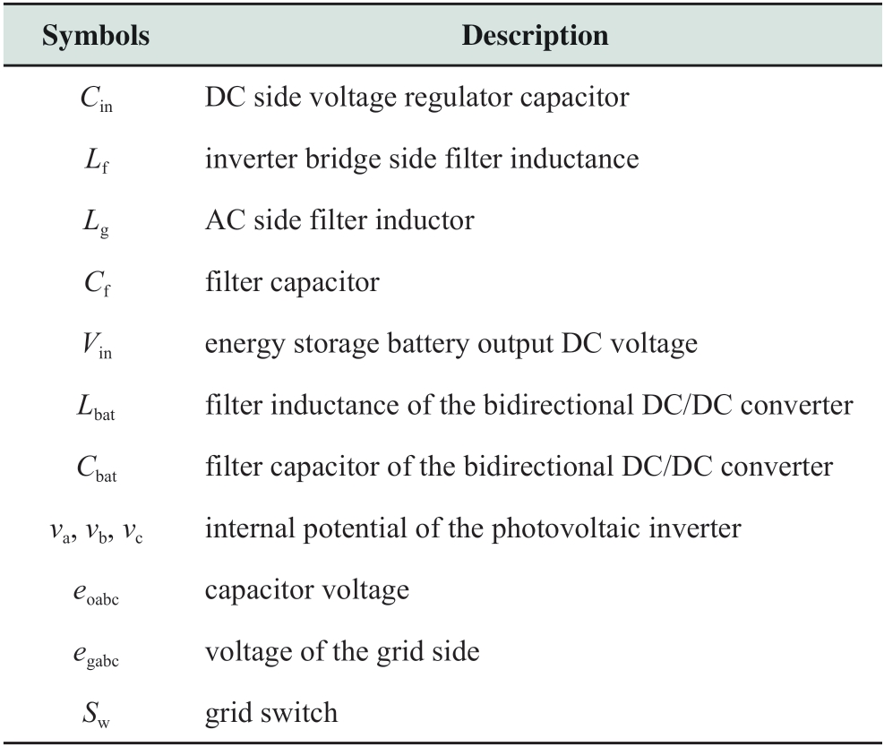
The structure of a single-stage PV-storage gridconnected power generation system based on the common DC bus structure is shown in Fig.1.It includes a photovoltaic array, energy storage battery, bidirectional DC/DC converter, photovoltaic inverter, LCL filter, and a grid.The energy storage battery is connected in parallel with the photovoltaic array through the bidirectional DC/DC converter on the DC bus, and the DC power is input to the PV inverter through the voltage regulator capacitor, which is converted into AC power by the inverter.Then, the AC power is output to the grid through the filter circuit.The circuit output is connected to the grid by a grid-connected switch.When the grid is faulty, the grid-connected switch is disconnected and operated in the island mode.
The bidirectional DC/DC converter can realize bidirectional transmission of energy, and its topology can be divided into isolated and non-isolated [19].The nonisolated bidirectional DC/DC converter has high conversion efficiency, small volume, and low cost; further, it is easy to design.The bidirectional Buck/Boost converter topology and control strategy are relatively simple, and fewer switching devices are needed.Therefore, a non-isolated bidirectional Buck/Boost converter is selected in this paper.
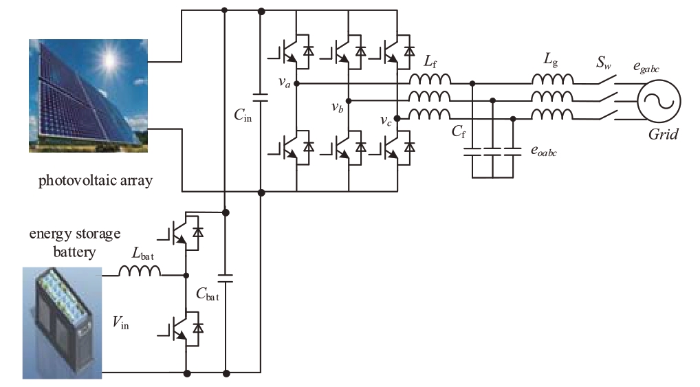
Fig.1 Structure of PV-storage grid-connected power generation system
Table 1 Description of symbols
2.2 Control strategies
This paper proposes a control strategy for a PV-storage grid-connected power generation system that clarifies the function distribution, simplifies the coordination control, and smoothens the photovoltaic inverter output power.
(1) PV inverter: In the control strategy proposed in this paper, the PV inverter implements the VSG algorithm, which constitutes the PV-VSG.Based on the characteristics of primary frequency modulation, primary voltage regulation, and the inertia and damping of traditional synchronous generators, PV inverters exhibit characteristics of a conventional synchronous generator.
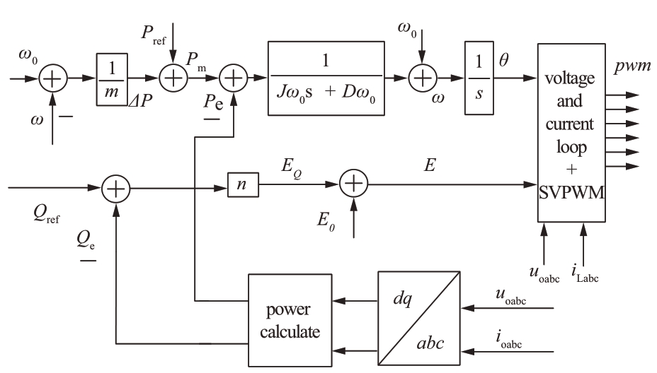
Fig.2 PV inverter control block diagram
The rotor motion equation of a conventional synchronous generator is given by [20]
where ω is the rotor angular velocity, ω0 is the no-load rotor angular velocity, ωN is the rated rotor angular velocity, Pm is the mechanical power of the synchronous generator, Pe is the electromagnetic power of the synchronous generator, J is the inertia coefficient, and D is the damping coefficient.
The mechanical power of PV-VSG is a superposition of the primary frequency power and the given power.The expression is
where Pref is the active power reference value and m is the primary frequency modulation coefficient.
The electromagnetic power of PV-VSG is calculated based on the instantaneous power theory, using the grid-side capacitor voltage and the grid-side inductor current in the dq coordinate system.The expression is given by
where uod and uoq are the d-axis and q-axis components of the grid-side capacitor voltage, respectively; iod and ioq are the d-axis and q-axis components of the grid side inductor current; and ωc is the cutoff frequency of the low-pass filter.
The electromagnetic equation of PV-VSG is
where L is the armature inductance, r is the armature resistance, iabc is the output current of the inverter, and

where E is the internal potential amplitude, and θ is the phase.Here,
The transient electromotive force is obtained according to the PV-VSG primary voltage regulation equation
where n is the reactive power droop coefficient, Qref is the upper reactive power command, and Qe is the reactive power, and E0 is the reference electromotive force.According to the instantaneous power theory, the reactive power is calculated as
The internal potential amplitude and phase are obtained according to Eqs.(1)-(8), and the modulated signal of the three-phase inverter is obtained by the underlying voltagecurrent double closed-loop control and Space Vector Pulse Width Modulation(SVPWM).
(2) Bidirectional DC/DC converter: A bidirectional DC/DC converter is connected between the energy storage battery and the DC-side filter capacitor; it achieves two purposes.One is maintaining the stability of the DC bus voltage, and the other is implementing the MPPT algorithm.The control block diagram is shown in Fig.3.

Fig.3 Bidirectional DC/DC converter control block diagram
In Fig.3, uPV is the output voltage of the PV array, iPV is the output current of the PV array, and uMPPT is the reference voltage of the MPPT output.The bidirectional DC/DC converter adopts a classical disturbance observation method to realize the maximum power point tracking algorithm, and it controls the DC-side capacitor voltage of the photovoltaic inverter; thus, the PV array operates at the maximum power point.After the reference voltage obtained by the MPPT is compared with the DC-side capacitor voltage, the reference current is obtained by the PI controller, and after passing through the current inner loop, the PWM signal is obtained after PWM.
(3) Coordinated control strategy of the system: The process of energy flow is obtained by analyzing the activefrequency adjustment process in the proposed control strategy to clarify the coordinated control strategy of the system.
The active-frequency adjustment process is shown in Fig.4.When f2 < f < f1 and in the FM dead zone S0, the main purpose is photovoltaic power generation.Energy is transported from the PV array to the grid.When f4 < f < f2, it is mainly to adjust the grid frequency in region S2.When the photovoltaic power is insufficient, the output power of the energy storage unit is supplemented.When f1 < f < f3 and in the region S1, the PV array transmits energy to the grid according to the droop curve and the primary frequency modulation characteristic; the excess energy is delivered to the energy storage unit.Therefore, the PV array, energy storage unit, and photovoltaic inverter generate energy interaction on the DC-side filter capacitor; however, the control strategy for the energy storage unit and the photovoltaic inverter are completely functionally independent, and this weakens the contradiction between energy matching.When the PV array output power is greater than the PV inverter output power, the energy storage battery absorbs the excess energy.When the PV array output power is less than the photovoltaic inverter output power, the energy storage battery provides the difference in energy.
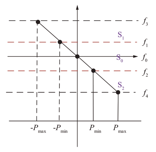
Fig.4 Active-frequency adjustment schematic
The control methods mentioned in [15] and [16]—MPPT—is realized by photovoltaic inverters.Since the photovoltaic inverters output at maximum power, the power fluctuations caused by the MPPT algorithm and external environment changes are reflected in the gridconnected current.First, because of the division in control functions, it is necessary for the energy storage unit to accurately control the DC-side voltage, which weakens the contradictory relationship among the energy matching of PV array, photovoltaic inverter and energy storage batter; thus, the requirement for coordinated control in this strategy is overcome.Second, this strategy uses a filtering link with a time delay because the control strategy proposed in this paper requires less coordinated control, and thus, the output of the photovoltaic inverter with the maximum power can lag behind that of the photovoltaic inverter.When the photovoltaic inverter outputs power for lagging the maximum power, the maximum power can be filtered using large time constant low-pass filtering to minimize the impact of power fluctuations, and the power difference after the filtering can be compensated by the energy storage.Therefore, in the strategy proposed in this paper, it is necessary to calculate the output power of the PV array at all times, and the PV array output power is passed through a low-pass filter with a large time constant to obtain the given power of the photovoltaic inverter.
To prevent the DC-side voltage drop caused by the sudden drop of illumination and the isolation of the energy storage unit, a limited power is superimposed on the photovoltaic inverter power reference.Set the minimum voltage value of the DC side as the DC side warning voltage.The value is higher than the inverter failure voltage, and the PI controller is set to the output maximum of 0.When the DC side voltage is higher than the warning voltage, the PI controller output is 0, that is, the limit power output is 0; when the DC side voltage is lower than the warning voltage, the PI controller output is negative, i.e., the limit power is negative, and the active power of the photovoltaic inverter is reduced, and thus, its output power is reduced to stabilize the DC side voltage.
In summary, the overall control block diagram of the control strategy proposed in this paper is shown in Fig.5.The control strategy proposed in this paper includes two parts: first, energy storage unit and photovoltaic inverter function allocation.The energy storage unit implements MPPT and the photovoltaic inverter implements VSG.Second, because of the clear function of each part, the coordinated control requirements are reduced.The output of the photovoltaic inverter can lag behind the output of the photovoltaic array.The Ppv obtained after filtering the output power of the energy storage unit and the limit power Plimit to ensure the stability of the DC-side voltage are superimposed as the power command Pref of the VSG.
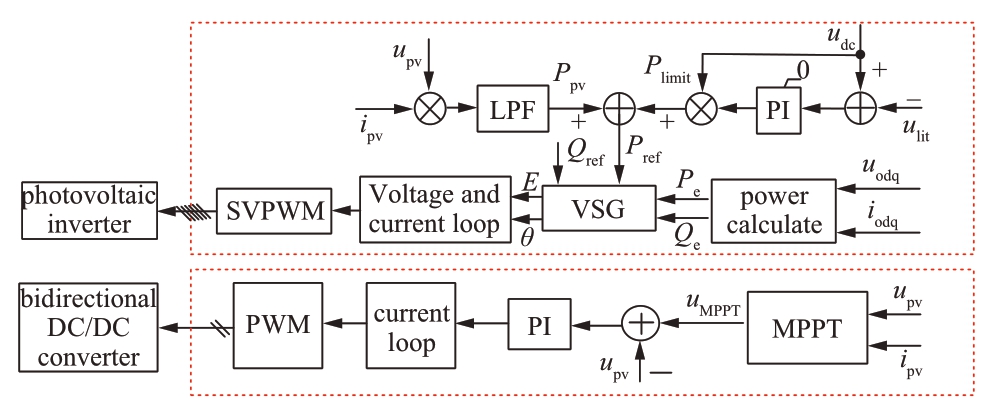
Fig.5 Overall control block diagram
2.3 Energy storage capacity ratio
When the grid frequency changes, the virtual synchronous generator uses its own inertia and damping response to suppress the change in frequency; the energy storage system provides the energy required for frequency modulation.
Assume that the energy absorbed or released by the energy storage system during the transient frequency modulation process is [21]

where EJ is the energy released or absorbed by the energy storage, Pn is the installed capacity of the photovoltaic power plant, TJ is the inertia constant; and fn and f are the grid rated and transient frequency values, respectively.
Differentiate both sides of Eq.(9) to obtain the power required for energy storage in the photovoltaic power plant to participate in the transient frequency adjustment as
where PJ is the transient frequency regulating power.
Assuming TJ = 5 s, Δt = 5 s, and Δf = ±0.25 Hz; PJ is given by
Considering the energy absorbed or released by the energy storage system during prime frequency regulation, according to the traditional steam turbine, the power required for prime frequency regulation is [22]
where δ is the speed governing droop, Δf is the frequency variation, and Δt is frequency modulation time.
Assuming δ = 5%, ΔP is given by
In summary, according to the requirements of transient frequency modulation and primary frequency regulation, the capacity of the energy storage system can be set to 10% of the capacity of the PV generation system.
3 Simulation
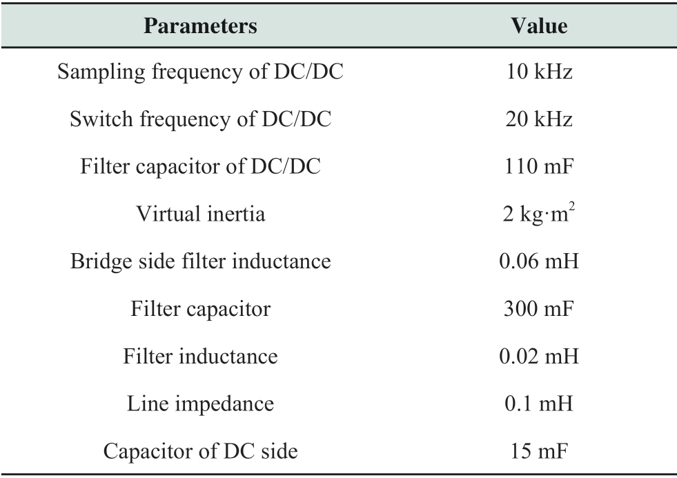
To verify the effectiveness of the proposed strategy, a simulation is built using MATLAB/Simulink.The weak grid is simulated with a 500-kW voltage source VSG in a series connection with a line impedance.The nominal capacity of the photovoltaic inverter is 500 kVA, and the energy storage unit is equipped with 50 kW.The simulation model is shown in Fig.6, and the simulation parameters are summarized in Table 2.The simulations verify the grid-connected operating condition, frequency-modulated operating condition, and the illumination sudden-drop condition.Among them, the proposed control strategy is compared with the literature [15, 16] in the FM operating conditions.The strategy in ref.[15] is defined as scheme 1, and that in ref.[16] is defined as scheme 2.
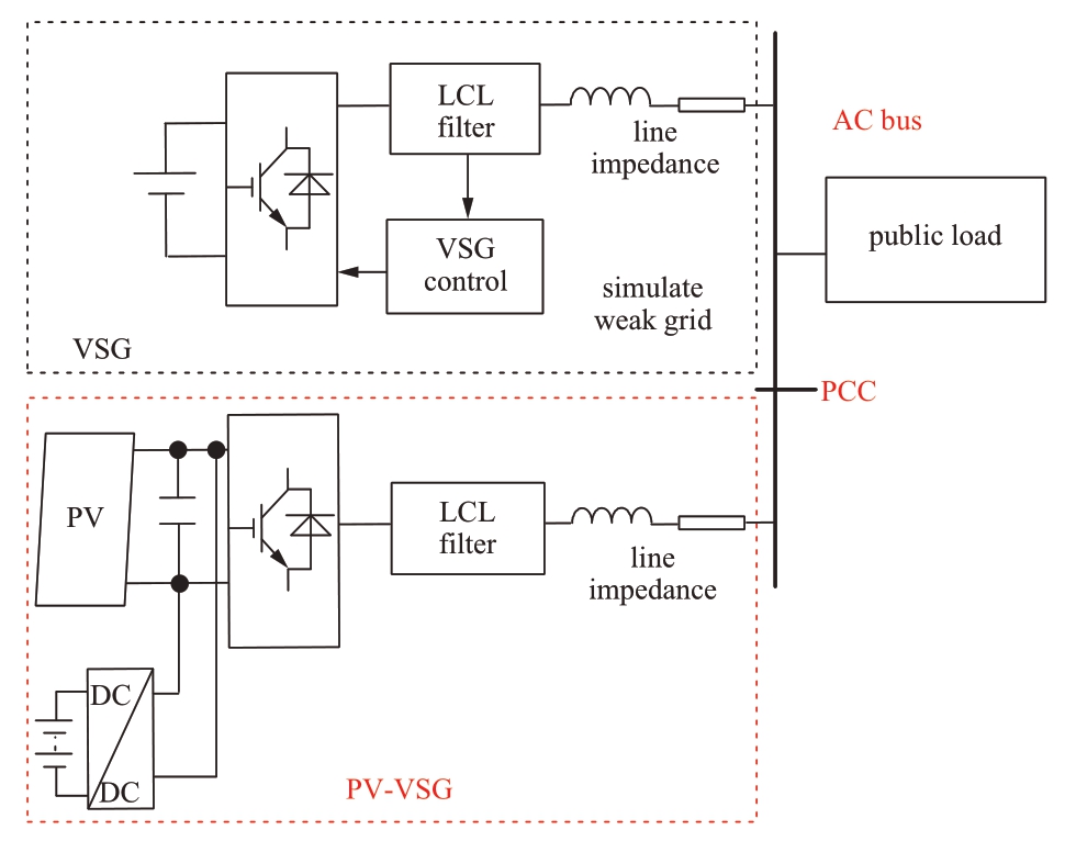
Fig.6 Structure of simulation model
Table 2 Parameters of simulation

continue
3.1 Grid-connected operating condition
At 0 s, the MPPT starts, the photovoltaic inverter is connected to the grid, and the photovoltaic inverter outputs power at 0.2 s.The waveforms after 0.2 s are shown in Fig.7.
Fig.7(a) shows the photovoltaic inverter output power, PV array output power, and energy storage unit input power.Fig.7(b) shows the DC-side capacitor voltage.As shown in Fig.7(a), before 0.4 s, the power input to the energy storage unit is positive, i.e., a part of the PV array output power enters the energy storage battery, and it gradually decreases as the PV inverter output power and the PV array output power are balanced.The difference in the power between the two is provided by the energy storage unit.After 0.4 s, the energy of the energy storage unit fluctuates around zero.Further, the output power of the photovoltaic inverter lags behind the output power of the PV array, which reduces the difficulty of coordinated control.Fig.7(b) indicates that the bidirectional DC/DC converter can control the DC-side capacitor voltage and track the voltage at the maximum power point to obtain the maximum power.
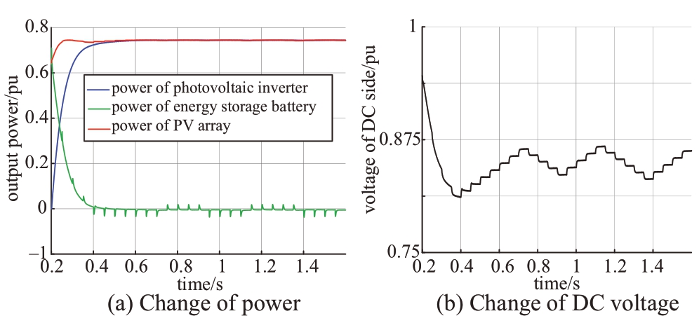
Fig.7 waveforms of grid-connected operating condition
3.2 Frequency-modulated operating condition
Figs.8, 9, and 10 show the frequency modulation waveforms for scheme 1, scheme 2, and the control strategy proposed in this paper, respectively.At 0.7 s, the 400-kW resistive load is suddenly increased; the 200 kW resistive load is suddenly dropped at 1.2 s.
As shown in Figs.8(a) and 9(a), after adding the frequency modulation to schemes 1 and 2, the load increases suddenly, and the grid frequency falls and recovers slowly, i.e., the inertia and damping of the grid are increased.As shown in Figs.8(b) and 9(b), the inverter output power increases at 0.7 s, the PV array output power remains unchanged, and the increase in the energy storage unit output power is equal to the output power of the PV inverter.At 1.2 s, the output power of the PV inverter is reduced, the output power of the PV array remains unchanged, and the output power reduction of the energy storage unit is equal to the reduction of the output power of the PV inverter, i.e., the energy storage unit provides differential power.The output power of the inverter fluctuates because of the MPPT algorithm, which causes the grid frequency, grid phase voltage, and phase current to fluctuate, as shown in Figs.8(c) and 9(c).According to Figs.8(d) and 9(d), during the frequency modulation process, the DC-side voltage maintains the maximum power point tracking state.
As shown in Fig.10(a), after the frequency modulation is added, the load suddenly increases, and the grid frequency falls and recovers slowly, i.e., the inertia and damping of the power grid are increased.As shown in Fig.10(b), the output power of the photovoltaic inverter increases at 0.7 s, the output power of the PV array does not change, and the increased output power of the energy storage unit equals that of the output power of the photovoltaic inverter.At 1.2 s, the output power of the inverter is reduced, the output power of the PV array remains unchanged, and the output power reduction of the energy storage unit is equal to the output power reduction of the photovoltaic inverter.That is, the energy storage unit provides the differential power, and the output power of the photovoltaic inverter is obviously improved.The grid-connected phase voltage and phase current are also output smoothly, as shown in Fig.10(c).According to Fig.10(d), during the frequency modulation process, the DC side always maintains the maximum power point tracking state.
On comparing the three schemes, the advantages of the control strategy proposed in this paper are: first, the output power of the PV inverter is smooth, which is because the MPPT algorithm is implemented by the energy storage unit and to transfer the power fluctuation to the energy storage unit.In schemes 1 and 2, the MPPT is realized by the photovoltaic inverter, and the power fluctuation occurs because of the presence of disturbance voltage.Second, the control strategy proposed in this paper reduces the coordinated control requirements of the system, and the output power of the photovoltaic inverter can lag behind the PV array.
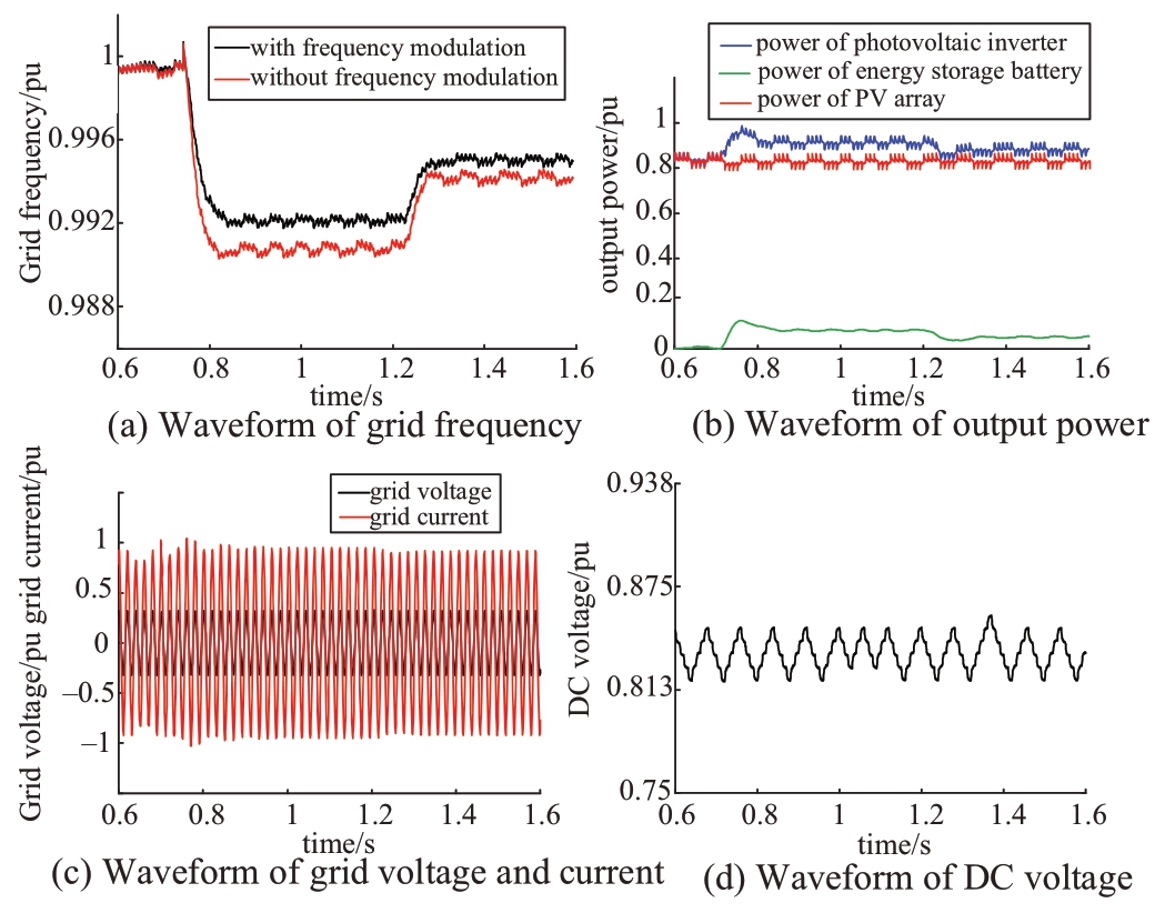
F ig.8 Frequency modulation waveforms of scheme 1
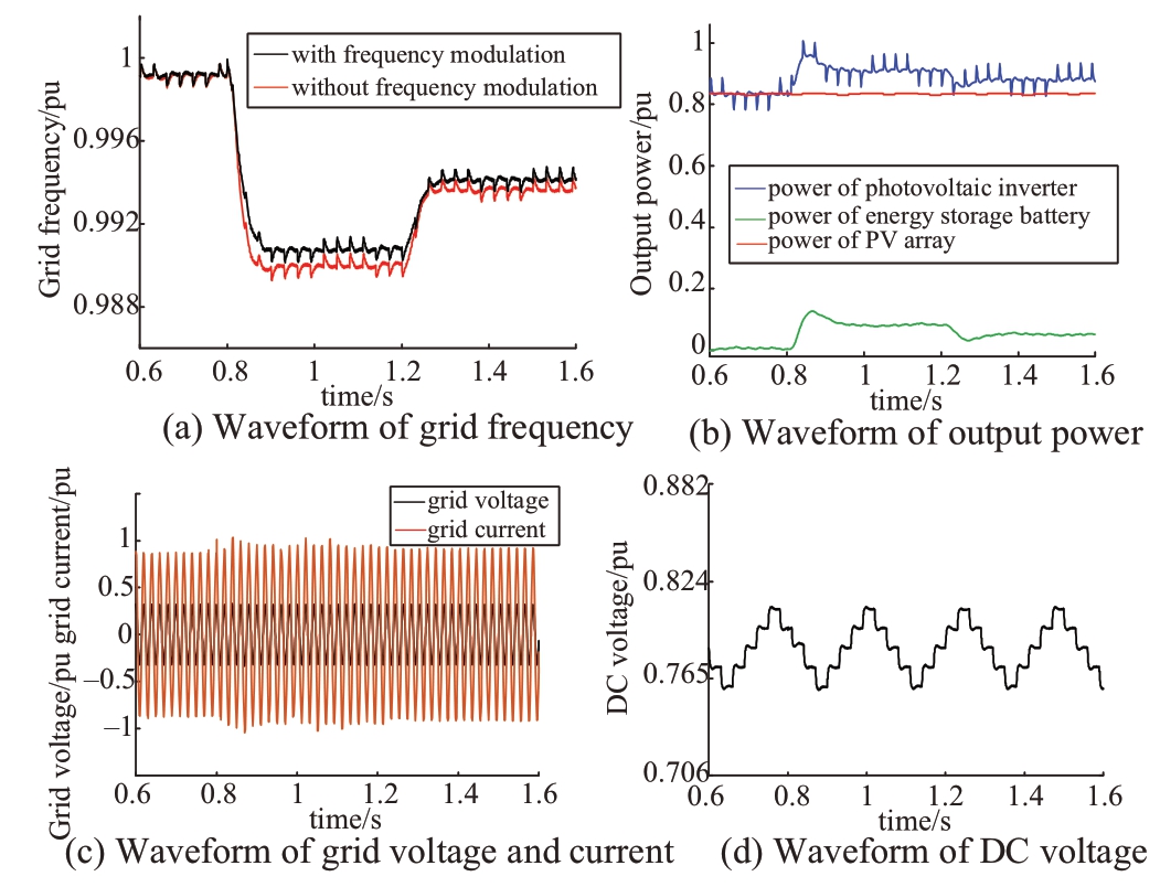
Fi g.9 Frequency modulation waveforms of scheme 2
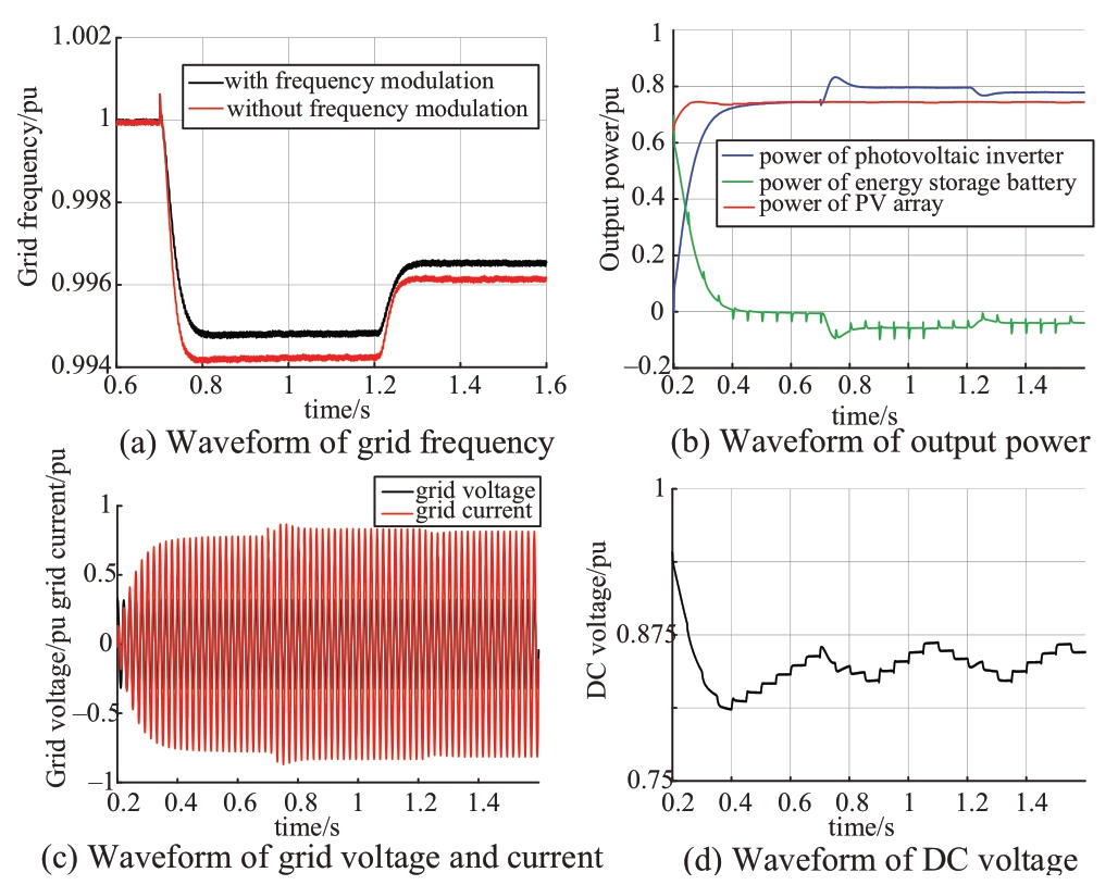
Fig.10 Frequency modulation waveforms of proposed strategy
3.3 Illumination sudden-drop operating condition
At 0.8 s, the illumination drops from 700 W/m2 to 500 W/m2; the simulation waveform is shown in Fig.11.According to Fig.11(a), when the illumination drops, the PV array output power drops, and the photovoltaic inverter output power drops slowly; the energy storage unit provides the differential power.As the output power of the photovoltaic inverter and the output power of the PV array are gradually balanced, the power of the energy storage unit gradually decreases and fluctuates around zero.As shown in Fig.11(b), because of the presence of the bidirectional DC/DC converter control, the DC side voltage does not have a large drop; however, it reaches a new balance point.
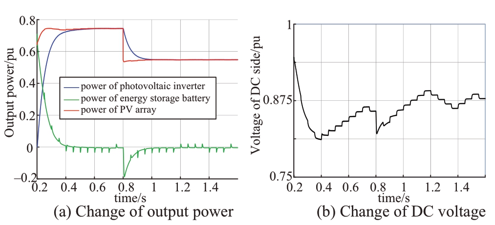
Fig.11 Waveforms of illumination drop operating condition
4 Conclusion
In this paper, based on the control strategy of singlestage PV-storage grid-connected power generation system with a common DC bus structure, we analyzed the contradiction between the coordinated control and the function allocation of the existing strategy and determined the fluctuation in the output power of the photovoltaic inverter.The control strategy of the PV-storage gridconnected power generation system was based on a virtual synchronous generator.The energy storage unit realized MPPT, the photovoltaic inverter realized VSG, and the VSG and MPPT functions were completely independent.The requirements for the system coordinated control were minimized, and simultaneously, the output power of the photovoltaic inverter lagged behind the PV array, and the output power of the PV array was given the power of the photovoltaic inverter through a low-pass filter with a large time constant to ensure that the output power of the photovoltaic inverter is smooth.The simulation results verified that the control method proposed in this paper can reduce the requirements of system coordinated control and smooth the output power of the photovoltaic inverter, which has certain engineering application value.
This paper does not consider the potential problems of stability when the energy storage unit operates at the transient, and only considers a single inverter.These are the contents that need future research.
Acknowledgements
This work was supported by National Natural Science Foundation of China Key program (51937003).
References
[1] Gosens J, Kåberger T, Wang Y (2017) China’s next renewable energy revolution: goals and mechanisms in the 13th Five Year Plan for energy.Energy Sci Eng 5(3):141-155
[2] Qingchang Z (2017) Virtual synchronous machines and autonomous power systems.Proc CSEE 37(2):336-348
[3] Zheng T, Chen L, Chen T, Mei SW (2015) Review and prospect of virtual synchronous generator technologies.Automat Electric Power Sys 39:165-75
[4] Zhipeng LÜ, Wanxing SH, Haitao LI (2017) Application and challenge of virtual synchronous machine technology in power system.Proc CSEE 37(2):349-59
[5] Wu W, Zhou L, Chen Y, Luo A, Dong Y, Zhou X, Xu Q, Yang L, Guerrero JM (2018) Sequence-impedance-based stability comparison between VSGs and traditional grid-connected inverters.IEEE Trans Power Electron 34(1):46-52
[6] Hou X, Sun Y, Zhang X, Lu J, Wang P, Guerrero JM (2019) Improvement of frequency regulation in VSG-based AC microgrid via adaptive virtual inertia.IEEE Tran Power Electron 35(2):1589-602
[7] Zhang H, Zhang X, Li M, et al.(2019) Control strategy of PVVSG in active power reserve mode based on power tracking with variable step.Automat Electric Power Sys 43(5): 92-100
[8] Liu H, Qiu L, Lan Z (2016) Study on virtual synchronous machine with energy storage unit.Acta Ed.Of Power.14(2): 1-8
[9] Yeting W, Dai Yuxing, Bi D (2017) A grid friendly PV/BESS distributed generation control strategy.Proc CSEE 37(2): 464-75
[10] Lin Y, Zhang J (2017) Coordinated control strategy of gridconnected virtual synchronous generator with photovoltaic and energy storage.Mod Electric Power 34(03): 69-75
[11] Wu D, Tang F, Dragicevic T, Vasquez JC, Guerrero JM (2015) A control architecture to coordinate renewable energy sources and energy storage systems in islanded microgrids.IEEE Trans Smart Grid 6(3): 1156-66
[12] Yin J, Chang L, Diduch C (2005) A new adaptive logic phaseshift algorithm for anti-islanding protections in inverter-based DG systems.In 2005 IEEE 36th Power Electron Special Conf 2482-2486
[13] Fang J, Tang Y, Li H, Li X (2017) A battery/ultracapacitor hybrid energy storage system for implementing the power management of virtual synchronous generators.IEEE Trans Power Electron 33(4):2820-4
[14] Wang Z, Yi H, Zhuo F, Sun L, Pei Y, Zhai H, Wu J (2017) A hardware structure of virtual synchronous generator in photovoltaic microgrid and its dynamic performance analysis.Proc CSEE 2:444-453
[15] Geng X, Peng Y (2018) A virtual synchronous generator system and control method for photovoltaic power plants.Shaanxi: CN108134402A
[16] Li Y, Zhang H, Wang L, et al.(2017) A virtual synchronous generator control method and device for photovoltaic energy storage system.Shaanxi: CN106549417A
[17] Shen Y, Yin Z, Zhang C (2011) PV power system energy control research in micro-grid.In 2011 Asia-Pacific Power Energy Eng Conf 1-3
[18] Karimi Y, Oraee H, Golsorkhi MS, et al.(2016) Decentralized method for load sharing and power management in a PV/Battery hybrid source islanded microgrid.IEEE Trans Power Electron 32(5):1-1
[19] Lang W, Lin W, Xu Y (2008) Status of circuit topology of bidirectional DC/DC converter.Acad Ann Meet Inst Power Electron, China Electrotech Soc
[20] Zhang X, Zhu DB, Xu H (2012) Review of virtual synchronous generator technology in distributed generation.J Power Supply 3
[21] Rubino S, Mazza A, Chicco G, Pastorelli M (2015) Advanced control of inverter-interfaced generation behaving as a virtual synchronous generator.In 2015 IEEE Eindhoven PowerTech 1-6
[22] Jingjing Z, Chuanlin X, Xue L (2017) Optimization of micro-grid primary frequency regulation reserve capacity and energy storage system.Proc CSEE 37(15):4324-32







Scan for more details
Received: 31 August 2019/ Accepted: 9 October 2019/ Published: 25 February 2020
 Xing Zhang
honglf@ustc.edu.cn
Qian Gao
1916889508@qq.com
Zixuan Guo
g_zixuan@126.com
Haizheng Zhang
zhanghz.vip@qq.com
Ming Li
645993986@qq.com
Fei Li
sandfl ylf@qq.com
2096-5117/© 2020 Global Energy Interconnection Development and Cooperation Organization.Production and hosting by Elsevier B.V.on behalf of KeAi Communications Co., Ltd.This is an open access article under the CC BY-NC-ND license (http: //creativecommons.org/licenses/by-nc-nd/4.0/ ).
Biographies
Xing Zhang received the B.S., M.S., and Ph.D.degrees at Hefei University of Technology, Hefei, China, in 1984, 1990, and 2003, respectively.Since 1984, he has been a Faculty Member in the School of Electrical Engineering and Automation, Hefei University of Technology, where he is currently a Professor and is also with the Photovoltaic Engineering Research Center of the Ministry of Education.His research interests include photovoltaic generation technologies, wind power generation technologies, and distributed generation systems.
Qian Gao received bachelor degree at Wuhan University of Technology, Wuhan, 2018.She is working towards master degree at Hefei University of Technology, Hefei.Her research interests includes control of VSG converters and photovoltaic generation technologies.
Zixuan Guo received B.S.degree at Hefei University of Technology, Hefei, 2016.He is currently working towards Ph.D.degree at Hefei University of Technology, Hefei.His research interests includes control of VSG converters and photovoltaic generation technologies.
Haizheng Zhang received B.S.degree at Xi’an University of Technology, Xi’an, 2016 and received M.S.degree at Hefei University of Technology, Hefei, 2019.His research interests includes control of VSG converters and photovoltaic generation technologies.
Ming Li received B.S.degree at Hefei University of Technology, Hefei, 2014.He is currently working towards Ph.D.degree at Hefei University of Technology, Hefei.His research interests includes parallel converter systems and photovoltaic generation technologies.
Fei Li received the B.S.and Ph.D.degrees at Hefei University of Technology, Hefei, China, in 2008 and 2015, respectively.Since 2015, he has been a Faculty Member with the School of Electric Engineering and Automation, Hefei University of Technology.His current research interests include filter topology and parameter design, harmonic mitigation in parallel converter systems, and photovoltaic generation technologies.
(Editor Dawei Wang)
